2
aquaguardpoolsystems.com
Safety Information
Safety Guidelines
This manual contains information that is very important
to know and understand. This information is provided for
SAFETY and to PREVENT EQUIPMENT PROBLEMS. To help
recognize this information, observe the following symbols.
DANGER: indicates imminently hazardous situations
which, if not avoided, WILL result in death or serious injury.
WARNING: indicates potentially hazardous situations
which, if not avoided, COULD result in death/serious injury.
CAUTION: indicates potentially hazardous situations
which, if not avoided, MAY result in minor/moderate injury.
NOTICE: indicates important information, that if not
followed, may cause damage to equipment.
NOTE: indicates information requires special attention.
General Safety Information
WARNING: California Proposition 65 - This product may
contain chemicals known to the State of California to
cause cancer and birth defects or other reproductive harm.
Wash hands after handling.
Read all product manuals carefully. Be familiar with
the controls and the proper use of the equipment.
WARNING: This lter operates under high
pressure. Incorrectly installed/serviced
equipment could explode, causing severe injury,
death, and/or property damage.
• Have a trained pool professional perform all pressure tests.
• Never connect lter to compressed air.
• Use lter only in a pool or spa installation.
• Never connect lter to external city/pressurized water.
• Do not connect to pumps that exceed 50 PSI pressure.
• Do not subject lter to pressure in excess of 50 PSI, even
when conducting hydrostatic pressure tests. Pressures
exceeding 50 psi can cause the tank to rupture and could
result in severe injury, death or property damage.
• Air trapped in the system can cause an explosion. Open
the air relief valve to vent all air from the system before
operating or testing the system.
WARNING: Do not use solvents to clean the lter assembly
as they may damage the plastic components.
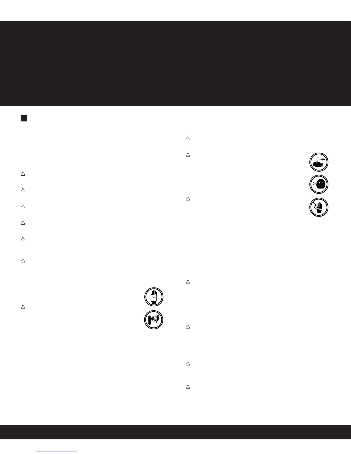
WARNING: Wear rubber gloves, protective
clothing and eye-wear when using acids and
cleaners. Avoid contact with skin and eyes.
If ingested, call local poison control center.
Observe all warnings and precautions supplied
with acids and cleaners.
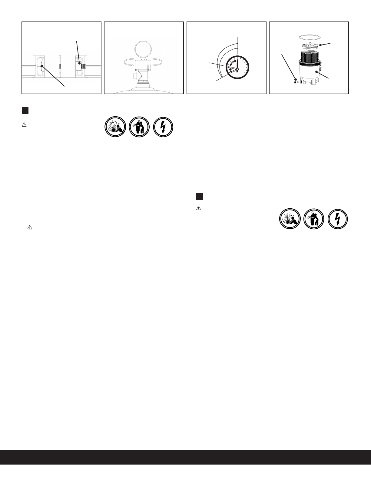
WARNING: Risk of electrical shock/electrocution.
• Position the lter drain and air relief valve to
safely direct drainage and purged air or water
away from the pump and other electrical
components. Water discharged from an improperly
positioned assembly can create an electrical hazard that
can cause serious injury, death, and/or property damage.
• Ensure lter installation, grounding and bonding meets
local codes and National Electrical Code (NEC) standards.
All wiring, grounding, and bonding of associated
equipment must be performed by a qualied electrician.
WARNING: Risk of falling and drowning.
• Place equipment 4 ft or more from pool so children cannot
climb over it into pool. Do not stand/play on equipment.
• Never leave lter open/unattended. Secure lter area.
• Keep children away from equipment at all times.
WARNING: This lter is designed to remove debris and
particulates from pool and spa water. Proper water
chemistry MUST be maintained to keep water clean and
avoid spreading diseases. Consult a local pool professional
for more information.
NOTICE: This lter is not designed for backwashing. If unit
is plumbed backwards or backwashed, it will damage the
lter cartridge and will void the warranty.
NOTICE: Attention Installer: This manual contains
important information about the installation, operation
and safe use of this lter. This information should be
furnished to the end user of this equipment.
Table of Contents
Safety Information ............................................................................ 2
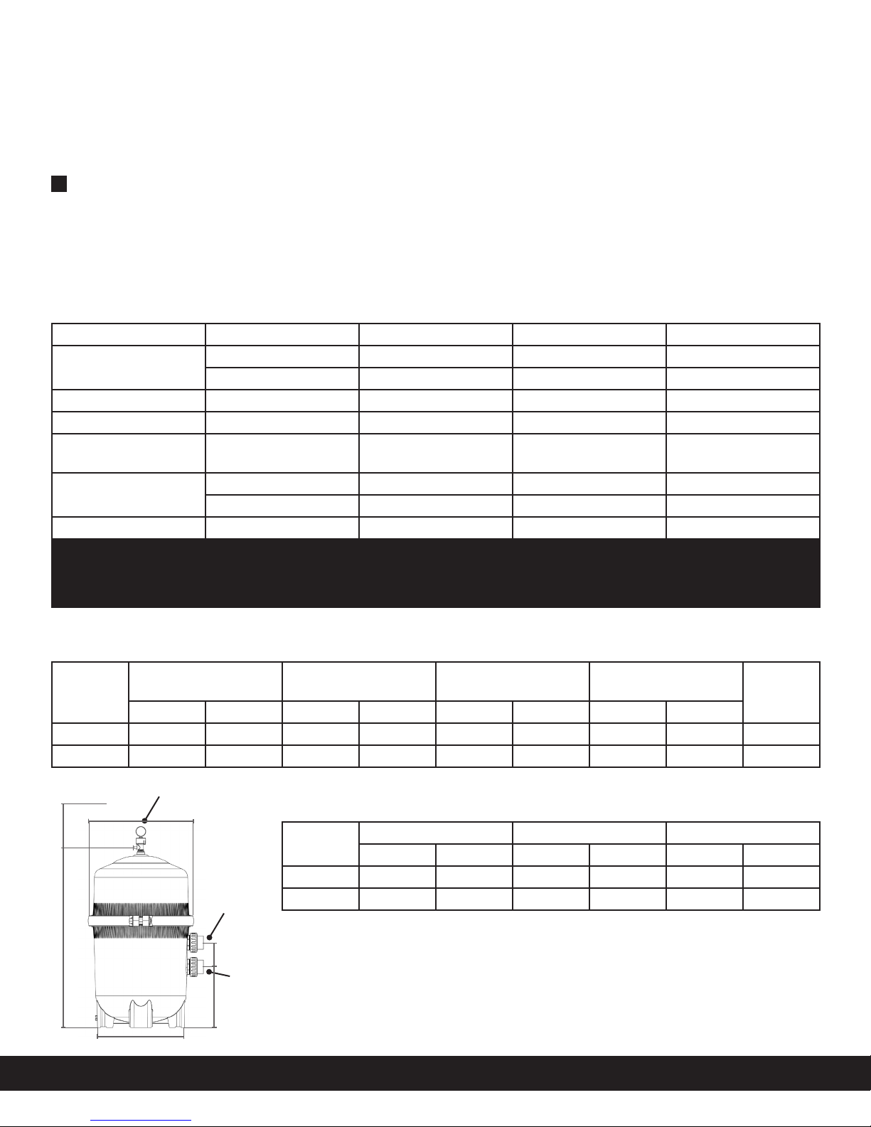
Product Specications ..................................................................... 3
Installation ........................................................................................... 4
Initial Startup ...................................................................................... 5
Maintaining Your Filter .................................................................... 5
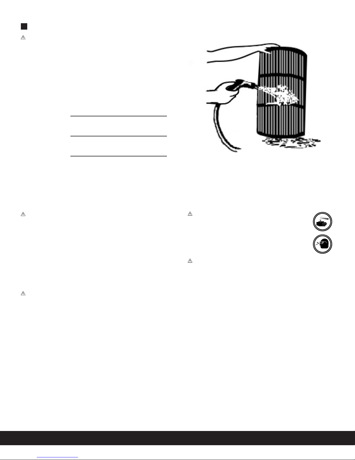
Cartridge Cleaning ............................................................................ 6
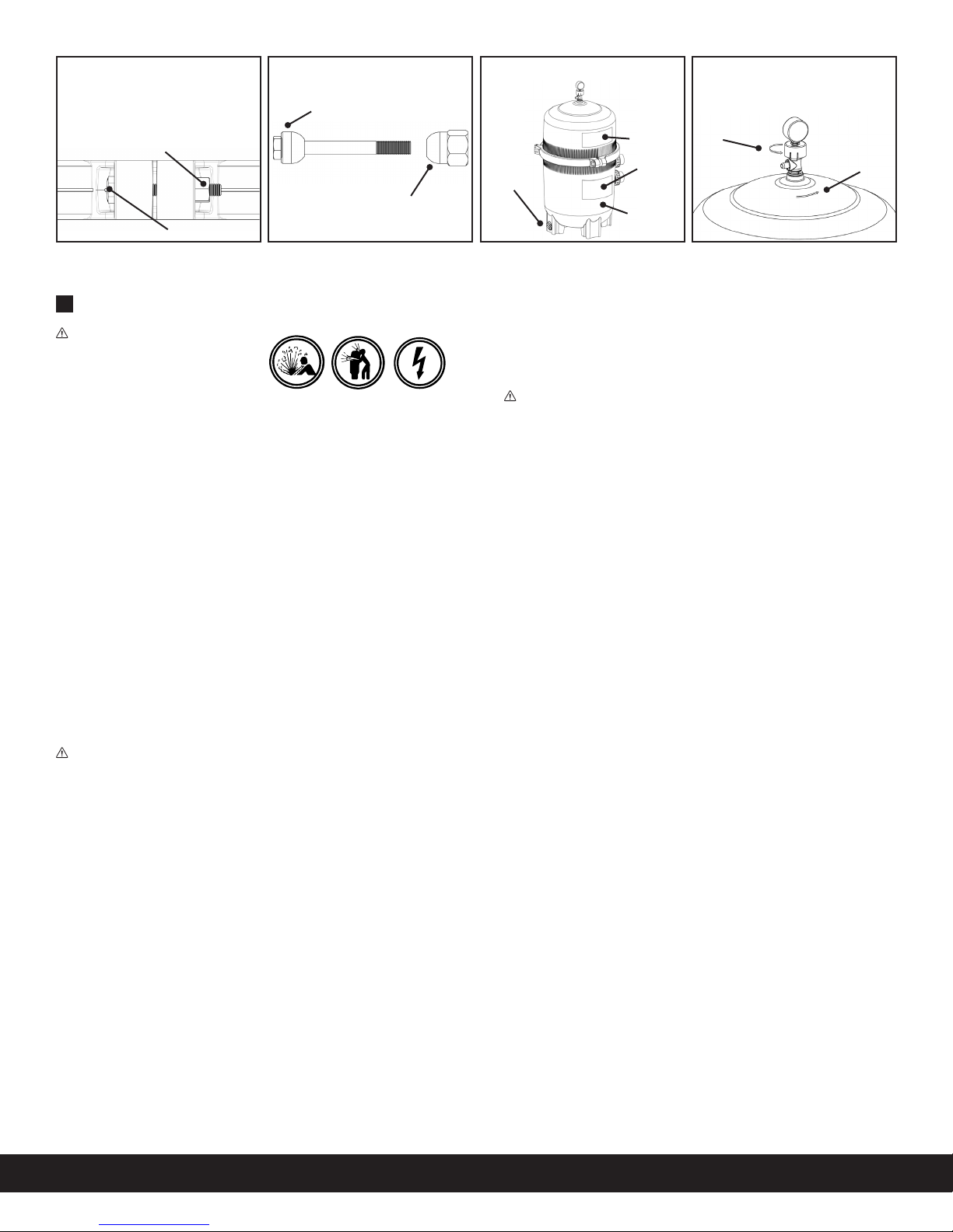
Filter Re-Assembly .............................................................................. 7
Trouble Shooting ............................................................................... 8
System Inspection ............................................................................. 9
Winterizing .......................................................................................... 9
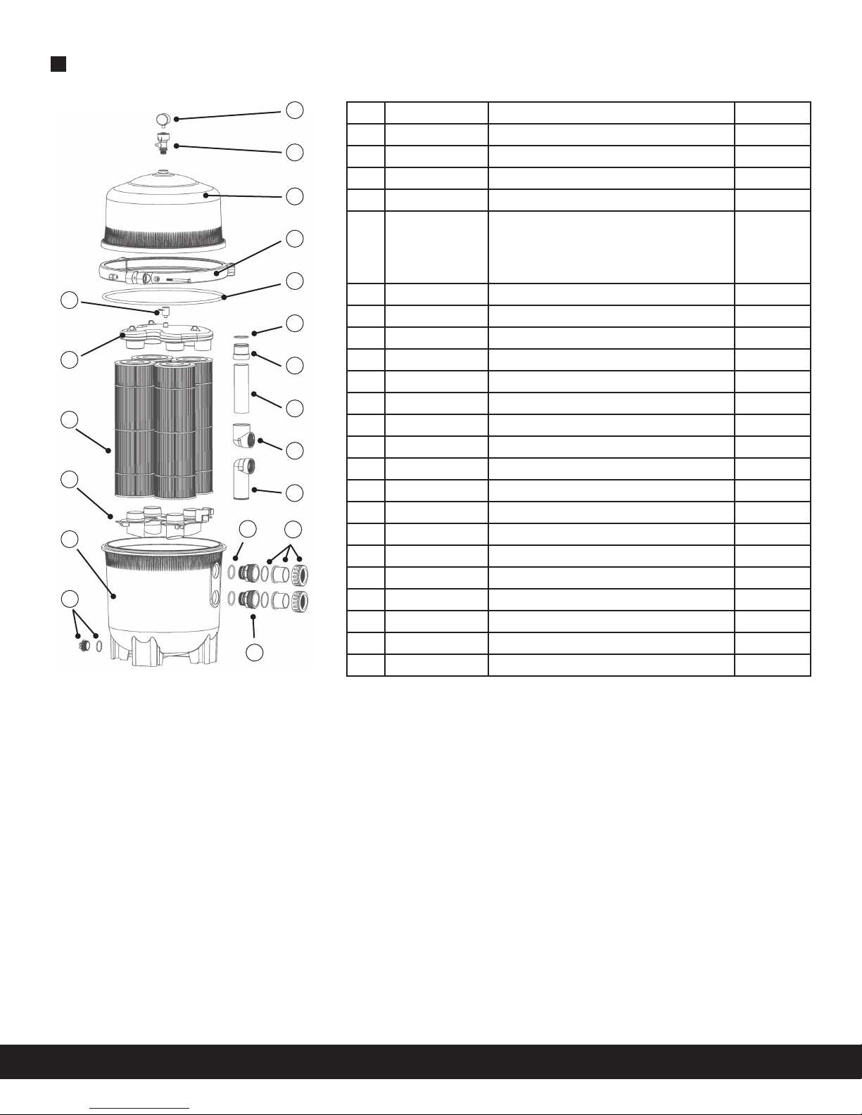
MasterPro Parts Listing .................................................................. 10
Warranty ............................................................................................. 11
SAVE THESE INSTRUCTIONS.