HOTLINE 1300 278 283 PHONE +61 (8) 6260 1000 EMAIL SALES@AQUAPROONLINE.COM.AU WEB WWW.AQUAPROONLINE.COM.AU
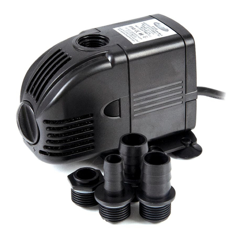
AP4800 PUMP
INSTRUCTIONS
• Using the 1 inch to ¾ inch threaded reducing nipple (10),
attach the Dual Control T-Piece (13) onto the pump outlet.
Adjust the telescopic riser (17-18) to the desired height, then
secure onto the top of the T-Piece using the threaded locking
nut provided. Align riser vertically.
• Locate the stepped hosetail locking nut (15), attach this to
the side outlet of the Dual Control T-Piece to facilitate an
optional accessory for example a filter or waterfall. Using the
Flow Adjustment Knob (12), on the T-Piece, you can vary
the flow between the fountain head and the waterfall outlet.
Close the second outlet of the T-Piece if this is not required.
Now connect tubing to the side Hosetail (14) if required. This
T-piece is not suitable for dry mount applications.
• Place the pump in desired location. Ensure the pump is on
a stable surface that is free of sludge, sand and other debris.
Position the device in the pond horizontally, on a solid base,
in such a way that it is fully covered with water and ensure
that the pump is located, at a depth, in the water, which will
not allow it to suck air from the surface. The fountain nozzle
should now be protruding out of the water.
• Push the plug into the power supply outlet and switch on.
• Remove the unit from the water. The filters and sponges
in this unit will clog over time. Please clean regularly (at
least once a month) to ensure strong water flow. Failure to
maintain the unit will result in a burnt out motor and other
damage.
• All AQUAPRO Pond & Fountain pumps are water cooled,
if pump becomes restricted, or blocked, it will overheat and
could cause permanent damage.
• Regular inspections, cleaning and maintenance of the
impellor is necessary to ensure longer life.
• Take o the fountain set first by unscrewing it from the top
of the pump. Examine the nozzles to ensure all ports are
unblocked. Clean with a suitable brush if necessary.
• Maintain the filter sponge regularly according to how long it
takes for the sponge to get clogged up. When the flow starts
to be reduced, check and clean if necessary.
• Unclip the front filter cage (1) from the front of the pump
buy pressing in the two catch tabs on either side, at the same
time, and pulling forward. Take out the Internal Bio Sponge
(2) and clean. If using an optional pre-filter block sponge,
slide the sponge o the threaded core and wash out. It is
recommended that this is done in a bucket of pond water to
ensure the good bacteria that are present in the sponge are
not killed by the Chlorine in tap water. Check for wear and
tear of the sponges. Replace if necessary.
• To maintain the impellor (6) of the pump, locate the locking
tab (5) near the outlet on the impellor cover. Click the tab
out from the motor body to unlatch. Now turn the Impellor
Cover (4) in an anti-clockwise direction to the stop position
and lift o. Then separate the impellor cover from the pump
motor body.
• Lift out the impellor assembly (6). (Take care not to break
ceramic shaft.) The black disc behind the blades is part of the
entire impellor assembly. Clean the impellor with clean water
and a suitable brush.
• It is important to ensure that this is carried out regularly as
the cooling path around the motor will become clogged. If
the impellor assembly becomes worn or damaged it should be
replaced (available from your dealer or special orders). Failure
to do so may cause serious damage to pump. Inspect for signs
for wear and tear. The impellor set is a wearing consumable
part.
• Once the cleaning and inspection process is completed,
reassemble in the reverses manner. Reinstall the impellor into
the motor body. To place the Impellor O-Ring (7) around the
black disc successfully, firmly hold the disc with one hand,
and using the other hand stretch the O-Ring over the disc,
positioning it carefully into the groove. Pay attention not
to allow the O-Ring to roll forward, in-between the black
disc and the motor body. With the impellor in the correct
position, carefully place the impellor cover (4) back on,
and then rotate clockwise back into position. Now slide the
locking tab (5) back into position to prevent the cover from
turning.
INSTALLATION
MAINTENANCE
ONCE A FOUNTAIN NOZZLE HAS BEEN SELECTED, ASSEMBLE THE FOUNTAIN KIT AS PER THE
DIAGRAM (SEE NEXT PAGE).
BEGIN BY ENSURING THAT THE MAINS POWER SUPPLY IS DISCONNECTED BEFORE
ATTEMPTING ANY MAINTENANCE OR ADJUSTMENT OF THE UNIT OR THE WATER BODY.
AQUAPRO AP4800 Instructions.indd 3AQUAPRO AP4800 Instructions.indd 3 13/5/2022 8:30 am13/5/2022 8:30 am


