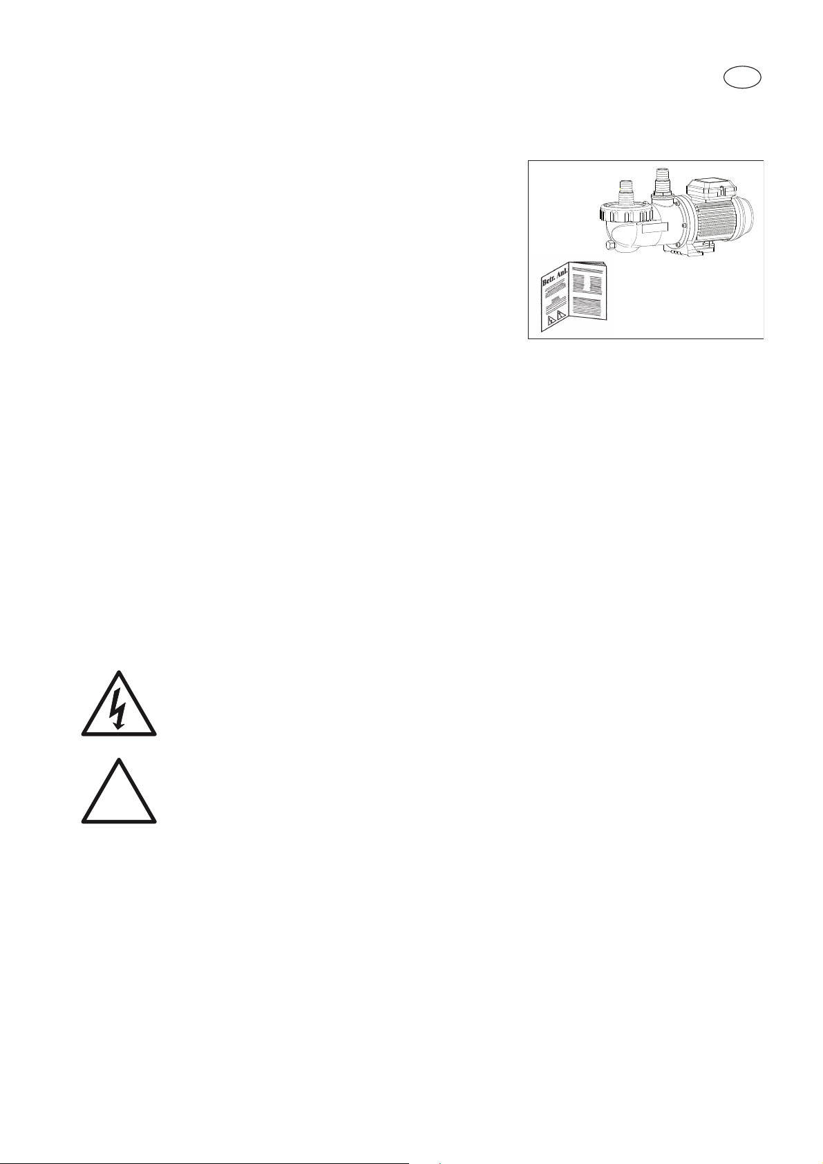
aqua technix AQUA Splash II Operation manual

AQUA Splash II
AQUA TECHNI
Umwälzpumpen, normalsaugend
Swimming pool filter circulation pumps, non-self priming
Pompes de circulation, non auto-amorçantes
Pompe de filtrazione, non autoadescanti
Circulatiepompen, normaalzuigend
Cirkulationspumpar, icke-självsugande
Oběhová čerpadla s normálním sáním
Cirkulačné čerpadlá s normálnym nasávaním
Pompe de circulaţie, neautoamorsante
DE
EN
FR
IT
NL
SV
CS
SK
RO
D42.02.319-P
Originalbetriebsanleitung
Translation of original operating manual
Traduction du mode d'emploi original
Traduzione del manuale d'istruzioni originali
Vertaling van de oorspronkelijke gebruikshandleiding
Översättning av originalbruksanvisningen
Překlad originálního návodu k provozu
Prestavno razmerje návod na montáž a obsluhu
Traducere din instrucţiunile de operare originale

DE
EN
FR
IT
NL
SV
CS
SK
RO
Originalbetriebsanleitung Seite 3
Umwälzpumpen, normalsaugend
Translation of original operating manual Page 10
Swimming pool filter circulation pumps,
non-self priming
Traduction du mode d'emploi original Page 17
Pompes de circulation, non auto-amorçantes
Traduzione del manuale d'istruzioni Pagina 24
originali
Pompe de filtrazione, non autoadescanti
Vertaling van de oorspronkelijke Pagina 31
gebruikshandleiding
Circulatiepompen, normaalzuigend
Översättning av originalbruksanvisningen Sid 38
Cirkulationspumpar, icke-självsugande
Překlad originálního návodu k provozu Straně45
Oběhová čerpadla s normálním sáním
Prestavno razmerje návod na montáž Strana 52
a obsluhu
Cirkulačné čerpadlá s normálnym nasávaním
Traducere din instrucţiunile de operare Pagina 59
originale
Pompe de circulaţie, neautoamorsante

3 |
1. Allgemeines
AQUA TechniX GmbH, Neunkirchen am Sand
2. Sicherheitshinweise
Mögliche Fehlanwendungen
- Einbau der Pumpe bei verspanntem Zustand des Rohrsystems.
- Betrieb der Pumpe außerhalb des Einsatzbereichs, der im
Pumpendatenblatt spezifiziert ist, zum Beispiel zu hoher
Systemdruck.
- Öffnen und Instandhalten der Pumpe durch nicht qualifiziertes
Personal.
Diese Betriebsanleitung enthält Hinweise, die bei Aufstellung,
Inbetriebnahme, Betrieb und Wartung der Pumpe zu beachten
sind.
Daher ist es wichtig, vor der Aufstellung der Pumpe, die
Betriebsanleitung sorgfältig zu lesen und am Einsatzort der
Maschine aufzubewahren. Die Betriebsanleitung muss jederzeit
für das bedienende Personal verfügbar sein.
Diese Pumpe kann von Kindern ab 8 Jahren und darüber sowie
von Personen mit verringerten physischen, sensorischen oder
mentalen Fähigkeiten oder Mangel an Erfahrung und Wissen
benutzt werden, wenn sie beaufsichtigt oder bezüglich des
sichereren Gebrauchs der Pumpe unterwiesen wurden und die
daraus resultierenden Gefahren verstehen. Kinder dürfen nicht
mit der Pumpe spielen. Reinigung und Benutzer-Wartung dürfen
nicht von Kindern ohne Beaufsichtigung durchgeführt werden.
Sicherheitszeichen
Warnung - Elektrische Spannung
Gefahr - bei Nichtbeachtung der Vorschriften
erhöht sich das Risiko, dass Personen und/
oder Sachen Schaden nehmen.
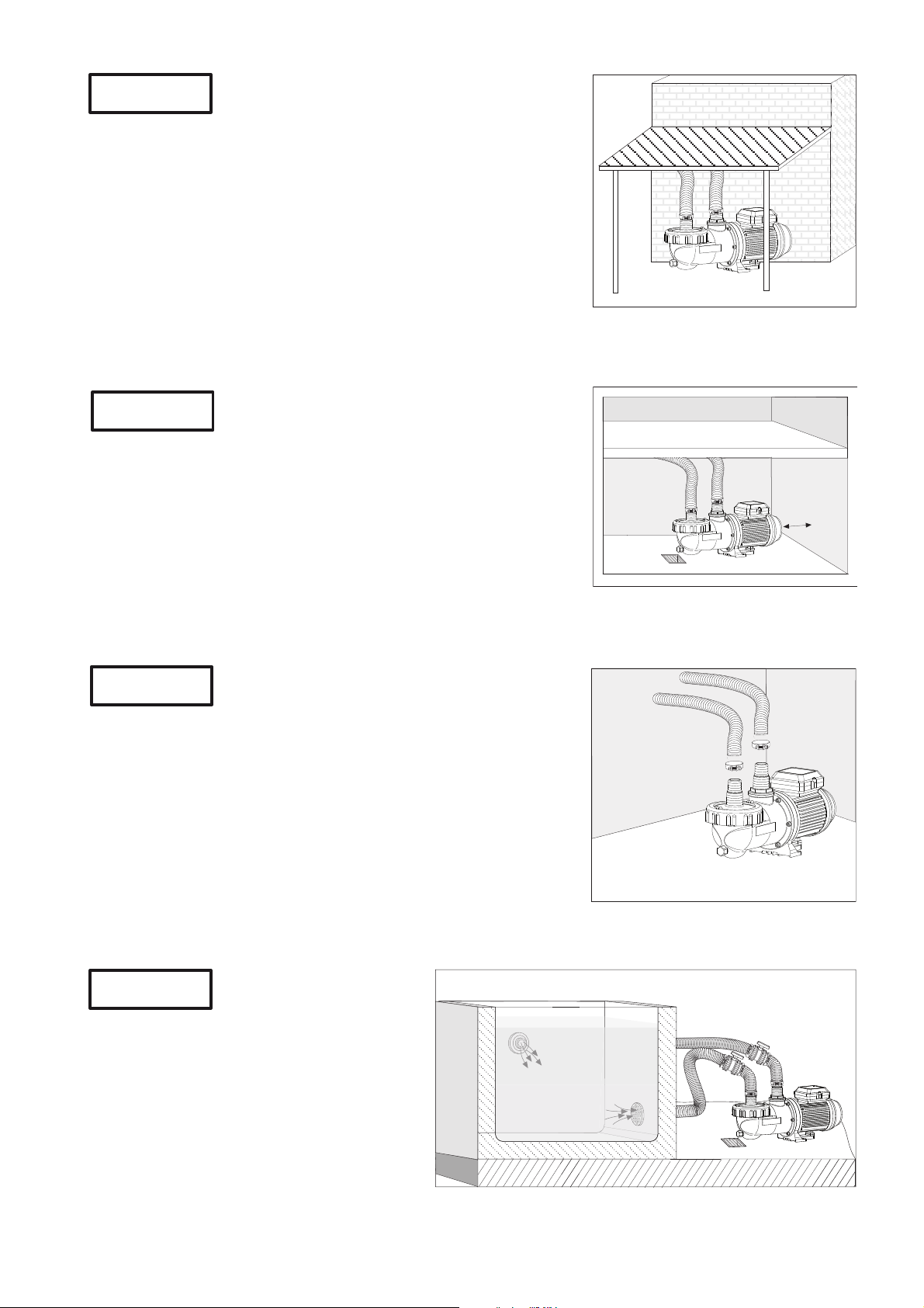
Restrisiken
Herabfallende Teile
Die Tragösen am Motor sind nur für das Gewicht des Motors
ausgelegt. Beim Anhängen eines kompletten Pumpenaggregats
können die Tragösen abbrechen.
- Pumpenaggregat, bestehend aus Motor und Pumpe, sowohl
motor- als auch pumpenseitig anhängen.
- Nur geeignete und technisch einwandfreie Hebezeuge und
Lastaufnahmemittel verwenden.
- Nicht unter schwebenden Lasten aufhalten.
!
D42.02.309-P
DE

| 4
D42.02.310-P
Rotierende Teile
Scher- und Quetschgefahr besteht aufgrund von offenliegenden rotierenden Teilen.
- Alle Arbeiten nur bei Stillstand der Pumpe durchführen.
- Vor Arbeiten die Pumpe gegen Wiedereinschalten sichern.
- Unmittelbar nach Abschluss der Arbeiten alle Schutzeinrichtungen wieder anbringen beziehungsweise
in Funktion setzen.
Elektrische Energie
Bei Arbeiten an der elektrischen Anlage besteht durch die feuchte Umgebung erhöhte Stromschlaggefahr.
Ebenso kann eine nicht ordnungsgemäß durchgeführte Installation der elektrischen Schutzleiter zum
Stromschlag führen, zum Beispiel Oxidation oder Kabelbruch.
• Sicherstellen, dass Schwimmbecken und Schutzbereich nach den regional geltenden Vorschriften
installiert, in Betrieb genommen und betrieben werden.
• Vor Arbeiten an der elektrischen Anlage folgende Maßnahmen ergreifen:
- Anlage von der Spannungsversorgung trennen.
- Warnschild anbringen: „Nicht einschalten! An der Anlage wird gearbeitet.“
- Spannungsfreiheit prüfen.
• Elektrische Anlage regelmäßig auf ordnungsgemäßen Zustand prüfen.
Heiße Oberflächen
Der Elektromotor kann eine Temperatur von bis zu 70 °C erreichen. Dadurch besteht Verbrennungsgefahr.
- Motor im Betrieb nicht berühren.
- Vor Arbeiten an der Pumpe Motor erst abkühlen lassen.
3. Allgemeine Hinweise
Es ist für einen sorgfältigen Transport zu sorgen. Bei der Zwischenlagerung sind hohe Luftfeuchtigkeit und
wechselnde Temperaturen zu vermeiden. Unsere Pumpe ist für das Umwälzen des Schwimmbadwassers
konzipiert.
Von uns verwendete Kunststoff-Materialien, die mit dem Medium in Berührung kommen, sind überwiegend
aus verstärktem PP hergestellt. Die Wassertemperatur darf 40 (60) °C nicht überschreiten.
Wir können keinerlei Haftung übernehmen, wenn unsere Montage- und Betriebsanleitung nicht beachtet
wird.
4. Montage
Der Aufstellungsort der Pumpe muss trocken und gut belüftet
sein.
Sollte die Pumpe in einem geschlossenen Raum aufgestellt
werden, muss ein Wasserablauf vorhanden sein.
Die Größe des Bodenablaufs richtet sich vor allem nach der
Größe des Schwimmbeckens, dem Umwälzvolumenstrom, aber
auch nach möglichen Leckagen im Badewasserumwälzsystem.
Die Umgebungstemperatur darf 40 °C nicht überschreiten.
Achtung

5 |
Im Freien dagegen, sollte die Pumpe einen einfachen Schutz
gegen Wettereinwirkungen wie z.B. Regen oder Sonne haben.
Durch geeignete Maßnahmen ist sicherzustellen, dass Körper-
oder Luftschall der Pumpe nicht in unzulässiger Weise die
Umgebung beeinträchtigt. Um einen Ausbau der Motoreinheit
nicht zu blockieren, befestigen Sie diese mit Schrauben, Gewinde
oder Dübel im Fundament. Bitte beachten Sie, dass ausreichend
Abstand zwischen Motorlüfterhaube und Wand vorhanden ist,
mindestens 60 mm, um die Motoreinheit ausbauen zu können.
Wir empfehlen zum Beispiel einen Spiralschlauch mit einer
Schlauchschelle als Verbindung zwischen dem Schwimmbecken
und der Pumpe zu verwenden.
Die Anschlussmöglichkeit bei der Aqua Splash II ist durch
Verwendung von Tüllen flexibel und leicht lösbar.
Die Saugleitung ist möglichst kurz zu halten.
Die Pumpe muss horizontal und trocken
aufgestellt werden. Die Aqua Splash II ist eine
normalsaugende Pumpe und darf deshalb nur
unterhalb des Wasserniveaus (Zulaufbetrieb,
maximal 3 m) montiert werden. In der Saug-
und Druckleitung ist ein Absperrschieber
vorzusehen.
D42.02.311-P
60mm
D42.02.312-P
D42.02.313-P
D42.02.314-P
Achtung
Achtung
Achtung
Achtung

| 6
5. Netzanschluss
Elektroanschluss nur durch einen Fachmann!
Vor Durchführung der Elektro- oder Wartungsarbeiten sind
alle Teile spannungsfrei zu machen.
Der Einsatz unserer Schwimmbadpumpen ist nur für
Schwimmbecken und deren Schutzbereiche zulässig, die die
DIN/VDE 0100 Teil 702 erfüllen. Die Pumpe darf nur über einen
Fehlerstromschutzschalter von IΔN≤30 mA betrieben werden.
Bitte darauf achten, dass in der Elektroinstallation eine
Trennvorrichtung vorgesehen ist, die das Abtrennen vom Netz mit
mindestens 3 mm Kontaktöffnung jedes Poles gestattet.
Entsprechend der Norm müssen die Leitungstypen H05RN–F
beziehungsweise H07RN–F verwendet werden.
Zusätzlich muss der zulässige Mindestquerschnitt entsprechend
der Motorleistung und der Leitungslänge angepasst werden.
Die Einphasenmotoren (Wechselstrom) verfügen über einen
eingebauten Wicklungsschutzkontakt.
6. Erstinbetriebnahme
Pumpe und Saugleitung langsam bis zum Druckanschluss mit
Wasser füllen. Die Pumpe nicht trocken laufen lassen! Auch
nicht zur Drehrichtungskontrolle!
Die eingebauten Absperrorgane in Saug- und Druckleitung
müssen bei Betrieb völlig geöffnet sein.
Achten Sie vor Inbetriebnahme oder nach längerem Stillstand auf
ein freies Drehen der Pumpenwelle.
7. Wartung
Vor Durchführung der Wartungsarbeiten ist die Pumpe vom
Stromnetz zu trennen. Bitte saug- und druckseitige Absperrorgane
schließen.
Wir empfehlen eine regelmäßige Reinigung des Saugsiebes. Bei
verschmutztem oder vollem Saugsieb geht der Förderstrom der
Pumpe zurück und es findet keine ausreichende Filtration statt.
Sollte die Anlage für längere Zeit nicht benutzt werden, ist eine
vollständige Entleerung und Reinigung der Pumpe dringend zu
empfehlen.
Bei Frostgefahr ist die Pumpe rechtzeitig zu entleeren.
Entleerung erfolgt durch Abziehen des Saugschlauches.
Frostgefährdete Leitungen ebenfalls entleeren.
Bei jeglichen Wartungsarbeiten ist die Pumpe vom Stromnetz
zu trennen.
!
Achtung
Achtung
D42.02.315-P
ON
OFF
0
C°
+10
-20
-10
+20
D42.02.316-P
Achtung

7 |
9. Empfehlung
Pumpen nur in gut vor Kindern gesicherten und abgeschlossenen
Räumen aufbauen.
Achten Sie auf die Eigenbelüftung des Motors. Der Aufstellungsort
der Pumpe muss trocken und gut belüftet sein.
Bitte keinerlei Fremdkörper in unmittelbarer Nähe der Pumpe
aufstellen.
Achtung !
D42.02.317-P
D42.02.318-P
Technische Daten bei 50 Hz Aqua Splash II-3 OL Aqua Splash II-4 Aqua Splash II-6
Saug Sa/Druck Da (Tülle) Ø32 / Ø32 Ø32 / Ø32 Ø38 / Ø38
Empf. Saug-/Druckleitung, Schlauch, d 1¼ / 1¼ 1¼ / 1¼ 1½ / 1½
Leistungsaufnahme P1(kW) 1~ 230 V 0,25 0,39 0,45
Leistungsabgabe P2(kW)
1~ 230 V 0,12 0,18 0,25
Nennstrom (A) 1~ 230 V 1,20 1,95 2,30
Gewicht (kg) 5,00 5,70 6,20
-
Schutzart IP X5
Wärmeklasse F
Drehzahl (min-1) ca. 2840
Dauerschalldruckpegel dB (A) ≤70 1)
Wassertemperatur (°C) max.
40 (60) *
Gehäuseinnendruck (bar) max. 2,5
Für Normspannung nach DIN IEC 60038
und DIN EN 60034 (Eurospannung).
Geeignet für Dauerbetrieb bei 1~ 220 - 240 V.
Toleranzen ± 5%.
1) Gemessen mit Schallpegelmeßgerät nach DIN 45635.
9. Technische Daten
* Erläuterung Wassertemperatur 40 (60) °C:
40 °C: gilt für maximale Wassertemperatur im Sinne des GS-Zeichens.
(60 °C): Pumpe ist ohne Weiteres für eine max. Wassertemperatur von 60 °C einsetzbar/ausgelegt.
Technische Änderungen vorbehalten!
8. Reparaturen
Alle Reparaturen dürfen nur durch den autorisierten
Kundendienst durchgeführt werden.

| 8
Technische Änderungen vorbehalten!
9. Technische Daten
H (m)
0
6
2
4
Q (m³/h)
Aqua Splash II-6
51015
10
8
Aqua Splash II-3 OL
Aqua Splash II-4
KL42.02.305-P
10
90
120
140
85 146
124
Schlauchtülle für 1¼ bzw. 1½ Schlauch
438
195 10
8
~60
Sa
Da
11571,5
D42.02.308-1-P

9 |
Pumpe saugt nicht an Pumpe ist undicht Zu geringer Förder-
strom Pumpe ist laut Pumpen-Motor läuft
nicht an Motorgeräusch Ursachen Abhilfe
XX Saugleitung undicht Saugleitung auf Dichtheit
überprüfen
XX Deckel undicht Deckel auf Dichtheit über-
prüfen
XGleitringdichtung undicht Gleitringdichtung vom
Fachmann austauschen *)
XPumpengehäuse ohne
Wasser
Pumpengehäuse mit Was-
ser auffüllen
XX Saugsieb ist verstopft Saugsieb muss gereinigt
werden
XSaugleitung nicht unter
Wasser
Saugleitung tiefer ins Was-
ser eintauchen
XX Pumpe über Wasserniveau Pumpe unter Wasserniveau
stellen
XX Saugleitung zu klein Saugleitung vergrößern
XSaug- oder Druckleitung
verstopft
Saug- und Druckleitung
reinigen
XX Fremdkörper in der Pumpe Pumpe und Laufrad über-
prüfen und reinigen
XStromzufuhr unterbrochen Stromzufuhr und Sicherun-
gen kontrollieren
XKondensator defekt Kondensator austauschen
XKugellager defekt Kugellager austauschen
XX
Pumpe blockiert (Sand in
der Pumpe)
Stromzufuhr unterbrechen,
mit einem Schraubendre-
her Leichtgängigkeit der
Motorwelle prüfen *)
*) Bitte vom Fachmann die Ursache der Störung überprüfen lassen!
Mögliche Defekte, Ursachen und Abhilfe

| 10
1. General
AQUA TechniX GmbH, Neunkirchen am Sand
2. Safety
Possible user errors
- Installation of the pump with the pipes under tension.
- Operation of the pump outside the area of application as
specified on the datasheet for e.g. excessive system pressure.
- Opening and servicing of the pump by unqualified persons.
This user guide contains basic instructions that must be followed
during installation, start-up, operation and maintenance of the
pump. The safety instructions must be observed.
Therefore, this manual must be carefully read before installation
and should be at all times available at the installation site. The
manual must always be available to the personnel in charge.
This pump can be used by children aged 8 and over as well as
by persons with limited physical, sensory or mental capacity or
by people with a lack of experience or knowledge, provided that
they are supervised or have been instructed in the safe use of the
pump and understand the resulting dangers. Children may not
play with the pump. Cleaning and user maintenance may not be
carried out by children without supervision.
Safety Symbols
Warning – Voltage
Danger – for safety warnings which, when
ignored, may constitute a hazard for the
machine and/or for persons.
Residual risks
Suspension parts - Risk of crushing from falling parts
The lifting lugs on the motor are only intended for holding the
weight of the motor. If they are used to lift the complete pump unit,
the lugs can break off.
- Make sure that the complete pump unit, that is both the motor
and pump are supported.
- Only use suitable lifting gear and load handling devices that are
in perfect working order.
- Do not stand under suspended loads.
!
D42.02.309-P
EN

11 |
D42.02.310-P
Rotating parts
Risk of crushing or shearing from exposed rotating parts.
- Do not perform any work on the pump unless the power is shut down.
- Before starting work, make sure the pump cannot inadvertently be switched on again.
- Directly after finishing work, refit/reactivate all protective devices
Electricity
When working on the electrical unit, there is an increased risk of electrocution due to the damp surroundings.
Incorrectly installed protective conductors can also lead to electrocution for e.g. as a result of oxidation or
cable breakage.
• Make sure that the swimming pool and its surrounding protective zone are installed,
commissioned and operated in accordance with the relevant local regulations.
• Before working on the electrical system, take the following precautions:
- Disconnect the system from the electrical power supply.
- Attach a warning sign: ”Do not switch on! Work in progress on the system.“
- Check the absence of voltage.
• Regularly check that the electrical system is in proper working order.
Hot surfaces
Risk of burns - the electric motor can reach temperatures of up to 70 °C.
- Do not touch the motor while it is running.
- Let the motor cool down before working on the pump.
3. General
Please take the necessary precautions when transporting the pump. During transportation, avoid
intermediate storage in a damp location or locations subject to significant temperature fluctuations. The
Splash II pumps have been designed for the circulation of swimming pool water.
Most plastic components that come into contact with the pumping medium are made of reinforced
polypropylene (PP) and thus are highly resistant to corrosion by pool water. The water temperature must
not exceed 40 (60) °C.
Non-compliance with our installation and operating instructions will void any warranty.
4. Installation
The installation site of the pump must be dry and well ventilated.
When installed in a closed room, a drainage connected to the
sewers must be installed.
The size of the floor drain depends mainly on the size of the
swimming pool and the circulation flow rate but also on possible
leaks within the pool water circulation system.
The ambient temperature must not exceed 40 °C.
Caution

| 12
When the pump is installed outside, we recommend to foresee a
simple protection against the weather (rain, sun etc.).
Implement appropriate measures to attenuate the noise generated
by the pump to avoid damage to the environment. Fastening the
pump to the foundation should be effected exclusively by means
of bolts, threads or dowels, in order to avoid blocking the removal
of the motor unit! Make sure that there is enough space between
fan cover and wall, minimum 60 mm.
We recommend the use of a spiral hose and a hose clamp to
connect the pump to the pool.
The connection to the pump is easy to undo and can be realised
in several ways due to the use of nozzles.
Keep the suction line as short as possible.
The pump should be installed horizontally
in a dry area. The Aqua Splash II is non-self
priming and must be installed below the water
level (up to 3 m max.). Suction and pressure
line are to be fitted with shut-off valves.
D42.02.311-P
60
mm
D42.02.312-P
D42.02.313-P
D42.02.314-P
Caution
Caution
Caution
Caution

13 |
5. Electrical Connection
All electrical connections should be performed by a qualified
expert only!
Make sure all parts are free of tension before doing any
maintenance work or electrical work.
The use of pumps for swimming pools and the restricted area
around them is only permitted if pumps are installed in accordance
with DIN/VDE 0100 part 702. The supply circuit has to be protected
with a fault current contactor with a nominal fault current of
IΔN≤30 mA.
Pl e as e m ake s ur e th a t th e e le c t r i c al installationhasa disconnecting
device, which allows disconnecting from the power supply with a
minimum of 3 mm contact gap at each pole.
In accordance with norm requirements an electrical cable type
H05RN-F or H07RN-F must be used.
Please ensure that the diameter of the electrical cable used
adequately accommodates for the power of the motor and the
length of the cable. Pumps with single-phase motor are equipped
with a built-in overload switch.
6. Initial Start-up
Slowly fill the pump until the water level reaches the outlet
connection. Never operate the pump without water even when
checking the rotation direction of the motor!
Ensure that all valves in the suction and pressure lines are
completely open.
Before initial start-up and after extended periods of downtime
make sure the pump shaft turns freely.
7. Maintenance
Before carrying out any maintenance work, the electricity supply
to the pump must be switched off. Close the shut-off valves on the
suction and on the pressure line.
The strainer basket must be periodically emptied. A clogged
strainer basket will reduce the flow rate of the pump and lead to
insufficient filtration. The pump is to be thoroughly drained and
cleaned after extended periods of storage or down-time.
If there is danger of freezing during prolonged periods, the pump
must be drained ahead of time. For this purpose remove the
suction hose in order to drain off all liquid. Drain all pipes subject
to freezing.
Before doing any maintenance work, switch off the pump
and disconnect it from the power supply.
!
D42.02.315-P
ON
OFF
0
C°
+10
-20
-10
+20
D42.02.316-P
Caution
Caution
Caution

| 14
D42.02.317-P
D42.02.318-P
9. Technical Data
* Explanation of water temperature 40 (60) °C:
40 °C: max. water temperature as certified by the GS approval.
(60 °C): pump in its current design is however usable/designed for a max. water temperatureof 60 °C.
Subject to technical modifications!
9. Recommendations
Only install the pump in a lockable room, out of the reach of
children.
Ensure the motor’s cooling. The installation site must be dry and
well ventilated.
Never obstruct the air supply to the fan by putting any objects on
the pump or too close to the pump.
!
Caution
Technical data at 50 Hz Aqua Splash II-3 OL Aqua Splash II-4 Aqua Splash II-6
Inlet Sa/outlet Da (nozzle) Ø32 / Ø32 Ø32 / Ø32 Ø38 / Ø38
Recommended inlet/outlet, PVC pipe, d 1¼ / 1¼ 1¼ / 1¼ 1½ / 1½
Power input P1(kW) 1~ 230 V 0.25 0.39 0.45
Power output P2(kW) 1~ 230 V 0.12 0.18 0.25
Rated current (A)
1~ 230 V 1.20 1.95 2.30
Weight (kg) 5.00 5.70 6.20
-
Type of motor enclosure IP X5
Thermal class F
Motor speed approx. (rpm) 2840
Max. continuous sound intensity
level dB (A)
70 1)
Max. water temperature (°C) max.
40 (60)
*
Max. casing interior pressure (bar) 2,5
For standard voltage according to DIN IEC 60038 and
DIN EN 60034 (Euro-voltage).
Suitable for continuous operation at 1~ 220 - 240 V.
Tolerances ±5 %.
1) Measured with phonometer according to DIN 45635.
8. Repairs
Repair are only to be done by an authorized service center.

15 |
Subject to technical modifications!
9. Technical Data
10
90
120
140
85 146
124
438
195 10
8
~60
Sa
Da
11571,5
D42.02.308-2-P
Hose nozzle for 1¼ or 1½ hose
H (m)
0
6
2
4
Q (m³/h)
Aqua Splash II-6
51015
10
8
Aqua Splash II-3 OL
Aqua Splash II-4
KL42.02.305-P

| 16
Pump doesn‘t
prime Pump leaks Flow rate is too weak Pump is noisy Pump/motor
doesn‘t start Motor is noisy Reason Solution
XX Leakage in inlet pipe Check the inlet pipe for
leakage
XX Lid is leaky Eliminate the leak
XMechanical seal is leaky Replace it (to be done by
an expert)
XNo water in pump casing Fill pump casing with water
XX Strainer is clogged Clean the strainer
XSuction line not below
water level Lower the suction line
XX Pump above water level Install pump below water
level
XX Dia. of suction line too
small
Use a suction line with
larger dia.
XSuction and pressure line
clogged
Clean suction and pressure
line
XX Foreign object in the pump Check and clean pump,
strainer and impeller
XPower supply interrupted Check power supply and
fuses
XDefective condenser Replace condenser
XDefective bearing Replace bearings
XX
Pump is blocked
(due to sand)
Stop power supply and
make sure pump turns free-
ly, by using a screwdriver *)
* The cause of the malfunction is to be determined by an expert.
Malfunctions / Trouble shooting

17 |
1. Généralités
AQUA TechniX GmbH, Neunkirchen am Sand
2. Sécurité
Consignes de sécurité sources de problèmes à éviter:
- Montage de la pompe avec canalisation déformée.
- Utilisation de la pompe hors du domaine d’utilisation spécifié
dans la fiche technique de la pompe (par ex. pression système
trop élevée).
- Ouverture et maintenance de la pompe par une personne non
qualifiée.
Le présent mode d’emploi donne des instructions de base qui
doivent être respectées lors de l’installation, de l’utilisation et de
l’entretien. Il est donc indispensable qu’il soit lu avant le montage.
Il doit constamment être à disposition sur le site d’utilisation du
personnel chargé de l’entretien.
Cette pompe peut être utilisée par des enfants âgés de 8 ans et
plus ainsi que par des personnes ayant des capacités physiques,
sensorielles ou intellectuelles limitées, ou ayant une expérience
ou une connaissance insuffisante du produit, si elles se trouvent
sous surveillance ou ont été initiées à l‘utilisation sûre de la
pompe et comprennent les dangers en découlant. Les enfants ne
doivent pas jouer avec la pompe. Le nettoyage et la maintenance
dévolue à l’utilisateur ne doivent pas être effectués par des
enfants laissés sans surveillance.
Signalisation des instructions dans le mode
d’emploi
Attention: tension électrique
Danger: Le non-respect des instructions de
sécurité peut provoquer des dangers tant pour
les personnes que pour l’environnement et le
matériel.
Risques secondaires
Chute de pièces
Les œillets destinés au transport du moteur ne sont prévus que
pour soutenir le poids du moteur.
Ces œillets peuvent casser en suspendant un groupe moto-
pompe complet.
- l’ensemble motopompe (constitué du moteur et de la pompe)
doit être attaché aussi bien du côté moteur que du côté pompe.
- Seuls des dispositifs de levage appropriés, en parfait état
technique et avec une capacité de levage suffisante, doivent
être utilisés.
- Éviter de stationner sous des charges en suspension.
!
D42.02.309-P
FR

| 18
D42.02.310-P
Pièces en rotation
Risque de coincement et de cisaillement dû aux pièces en rotation apparentes.
- Effectuer l’ensemble des travaux uniquement à l’arrêt de la pompe.
- Avant de démarrer les travaux, sécuriser la pompe contre le ré-enclenchement.
- Dès la fin des travaux, ré-enclencher tous les dispositifs de protection ou les remettre en service.
Energie électrique
L’environnement humide entraîne un risque élevé d’électrocution lors de la réalisation de travaux sur une
installation électrique.
Un défaut de protection des câbles électriques conducteurs peut par ailleurs entraîner une électrocution
(par ex. par oxydation ou section de câble).
• Vérifier que la piscine et le périmètre de protection ont été construits, mis en service et fonctionnent
conformément aux réglementations de sécurité électrique en vigueur sur le lieu d’installation
(NF C15-100).
• Avant d’effectuer des travaux sur l’installation électrique, prendre les mesures suivantes:
- Couper l’alimentation électrique de l’installation.
- Apposer un panneau d’avertissement : « Ne pas mettre en marche ! Des travaux sont en train d’être
effectués sur l’installation. »
- Contrôler l’absence de tension.
• Contrôler régulièrement la conformité de l’installation électrique.
Surfaces chaudes
Le moteur électrique peut atteindre une température allant jusqu’à 70 °C. Risque de brûlure !
- Ne pas toucher le moteur lorsqu’il est en service.
- Laisser refroidir le moteur avant tous travaux sur la pompe.
3. Informations générales
Le plus grand soin doit être apporté au transport des pompes. Tout stockage intermédiaire de la pompe
dans un endroit à forte hygrométrie et sujet aux variations de température importantes est à éviter. Nos
pompes avec pré-filtre sont conçues pour la filtration et la circulation de l’eau de piscines.
Les pièces en contact avec l’eau sont pour la plupart en polypropylène PP. La température de l’eau ne doit
pas excéder 40 (60) °C.
Le non-respect des instructions de montage et d’utilisation peut provoquer le rejet d’éventuelles demandes
en indemnisation des dommages subis.
4. Montage
Installer la pompe dans un endroit au sec et aéré dans lequel la
température ambiante ne dépassera pas 40 °C.
Dans un endroit clos, il est obligatoire de prévoir une évacuation
de l’eau.
Le diamètre de la bonde d’écoulement de l’eau au niveau du
sol est surtout défini par la taille du bassin, du flux volumique
de circulation de l’eau également par la possibilité d’éventuelles
fuites dans le système de circulation de l’eau du bain.
Attention

19 |
Si la pompe est installée en plein air nous recommandons de
l’équiper d’une simple protection contre les intempéries ainsi que
contre les rayons du soleil.
La mise en place de mesures appropriées contre les nuisances
sonores engendrées par les pompes évitera des conséquences
dommageables sur l’environnement. Pour la fixation de la pompe
sur le socle ou sur la fondation, nous vous recommandons
d’utiliser des vis avec des chevilles pour éviter de bloquer tout
démontage de l’unité moteur ! Il faudra veiller à conserver un
espace suffisant (de 60 mm au minimum) entre le couvercle du
ventilateur et le mur.
Nous vous recommandons par exemple d’utiliser un tuyau flexible
et un collier de serrrage pour raccorder la pompe à la piscine.
Les possibilités de raccordement de l’Aqua Splash II, sont
variables et faciles à résoudre en utilisant des embouts cannelés.
Placer la pompe le plus près possible du bassin
pour réduire la longueur d’aspiration. Installer
la pompe à l’horizontale et dans un endroit
abrité. La pompe Aqua Splash II n’est pas
autoamorçante et ne devra pas être installée
au-dessus du niveau d’eau (fonctionnement
en charge de 3 m au maximum). Prévoir
l’installation d’une vanne d’arrêt sur la conduite
d’aspiration et de refoulement.
D42.02.311-P
60mm
D42.02.312-P
D42.02.313-P
D42.02.314-P
Attention
Attention
Attention
Attention

| 20
5. Raccordement au réseau électrique
Le branchement électrique doit être effectué obligatoire-
ment par un spécialiste !
Mettre hors tension toutes les unités avant l’exécution de
travaux électriques et demaintenance.
L’installation de nos pompes pour piscines est soumise au strict
respect des prescriptions de la norme DIN/VDE 0100 partie
702. Le circuit d’alimentation électrique devra être protégé par
un interrupteur différentiel équipé d’un courant de défaut nominal
IΔN≤30 mA.
Il faudra veiller à ce que le moteur de la pompe soit protégé par
un disjoncteur magnéto-thermique correctement calibré, avec
intervalle de coupure min. de 3 mm par borne. Conformément
aux prescriptions de la norme, employer des câbles de type
H05RN–F respectivement H07RN–F.
En outre, adapter la section minimum des câbles à la capacité du
moteur et à la longueur totale du circuit électrique. Les moteurs
à courant alternatif (monophasés) sont équipés d’un disjoncteur
thermique intégré dans le bobinage du moteur.
6. Première mise en service
Remplir lentement la pompe avec de l’eau jusqu’au raccord de
refoulement. Eviter de faire fonctionner la pompe sans eau,
même pour contrôler le sens de rotation du moteur!
Veiller à ce que les vannes d’arrêt montées sur les conduites
d’aspiration et de refoulement soient bien ouvertes lors de la mise
en service. Après une période d’arrêt prolongée de la pompe et
avant la remise en marche, vérifier que l’arbre tourne librement.
7. Entretien
Couper la pompe du réseau avant tout travail d’entretien. Fermer
les vannes d’arrêt du coté aspiration ainsi que du côté refoulement.
Le panier de pré-filtre doit être nettoyé de temps en temps.
Lorsque le panier est sale ou plein, le débit de la pompediminue
et la filtration n’est plus suffisante. Lors d’une période d’arrêt
prolongée de la pompe il est fortement recommandé de vidanger
complètement la pompet de la nettoyer.
En cas de risques de gel, vidanger la pompe en temps opportun.
La vidange de l’eau de la pompe s’effectue par la vis de
purge. Vidanger également les canalisations d’aspiration et de
refoulement.
Pour tous travaux d’entretien débrancher la pompe du
réseau électrique.
!
D42.02.315-P
ON
OFF
0
C°
+10
-20
-10
+20
D42.02.316-P
Attention
Attention
Attention
Table of contents
Languages:
Other aqua technix Swimming Pool Pump manuals
Popular Swimming Pool Pump manuals by other brands

Pulsar
Pulsar 79214 1 HP owner's manual

Pentair
Pentair IntelliFloXF Installation and user guide

Profi-pumpe
Profi-pumpe INVERT-YECH1 operating instructions

Outside Living Industries
Outside Living Industries Ubbink Heatermax Pool Note of assembly

STA-RITE
STA-RITE JWPD-075 owner's manual

Speck pumps
Speck pumps Swimming Pool Pump owner's manual

STAR Water Systems
STAR Water Systems SW1369 quick start guide

SUNPUMPS
SUNPUMPS SCP series Operation and installation manual

HydroAir
HydroAir Argonaut owner's manual

BADU
BADU JET Smart Operating and installation instruction

Polygroup
Polygroup SUMMER WAVES ST1100 owner's manual

STA-RITE
STA-RITE WATERFORD SYSTEMS JWPS5EL owner's manual