manuals.online logo
Brands
  1. Home
  2. •
  3. Brands
  4. •
  5. Polygroup
  6. •
  7. Swimming Pool Pump
  8. •
  9. Polygroup SUMMER WAVES ST1100 User manual

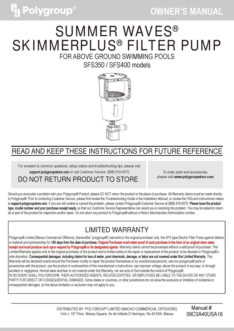
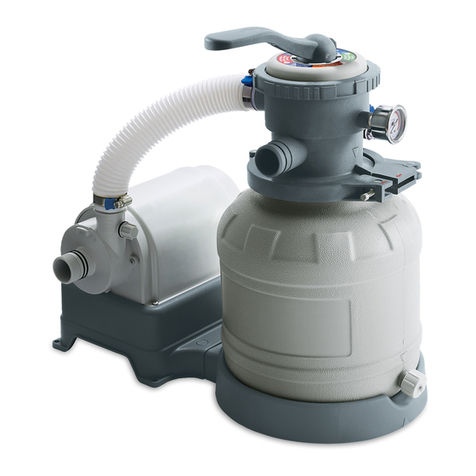
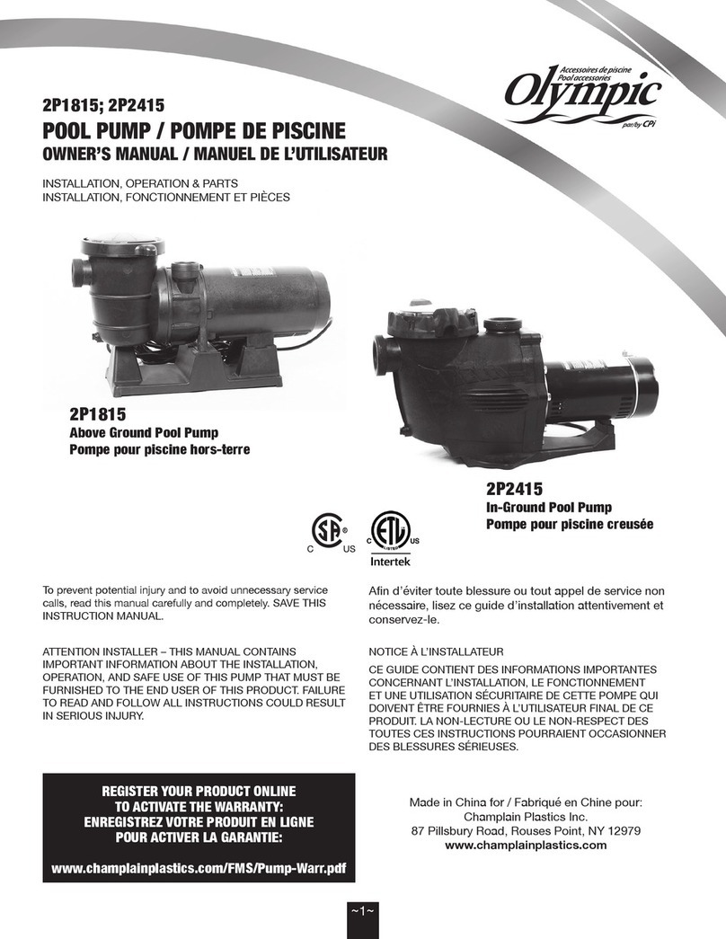
Polygroup SUMMER WAVES ST1100 User manual

EN
DISTRIBUTED BY: Polygroup®Trading Limited. Unit 606, 6th Floor, Fairmont House, No.8 Cotton Tree Drive, Central, Hong Kong.
For questions and issues, contact Customer Service at +1 (888) 919-0070 from 8AM to 5PM MST, Monday-Friday.
Extended operating days and hours during peak season requirements.
Polygroup®Trading Limited (hereinafter “Polygroup®”) makes products at the best quality we are able to offer. Polygroup®is pleased to
offer warranty for the repair or replacement of pool products for 180 days from the date of purchase. The provisions of this Limited
Warranty only apply to the original purchaser. Please keep your original store sales receipt, as this proof of purchase will be required and
must accompany warranty claims to Polygroup®or its designated agents. This Limited Warranty does not apply without proof of purchase;
or should the purchaser modify or repair the product themselves or by unauthorized people; use non-Polygroup®parts or accessories with
the product; use the product in contravention of the manufacturer’s instructions; use improper voltage; abuse the product in any way; or
through accident or negligence. This Limited Warranty will not cover consequential damages, including claims for loss of water, pool
chemicals, damage, or labor, normal wear-and-tear; nor acts of God outside the control of Polygroup®. Non-manufacturing defects, such
as grasses that may grow through the ground cloth and/or pool liner are examples of which Polygroup®cannot be held responsible for.
IN NO EVENT SHALL Polygroup®, ITS AUTHORIZED AGENTS, RELATED ENTITIES, OR EMPLOYEES BE LIABLE TO THE BUYER
OR ANY OTHER PARTY FOR DIRECT OR CONSEQUENTIAL DAMAGES. Some states or countries, or other jurisdictions, do not allow
the exclusion or limitation of incidental or consequential damages, so the above limitation or exclusion may not apply to you.
This Limited Warranty is not extended to close-outs, factory seconds, or resold products (i.e. garage sales, online auctions, or online
retailers not purchased directly from Polygroup®). Any issues with items purchased from these types of vendors / sellers will need to be
addressed through these stores. Items purchased from seasonal stores will be treated with an “All Sales Final” Policy.
Limited Warranty
Should you encounter a problem with your Polygroup®Product, DO NOT return the product to the place of purchase. All warranty claims must
be made
directly to Polygroup®. For any setup and troubleshooting issues, visit support.polygroupstore.com. Customer Service: +1 (888) 919-0070
.
You may be asked to return all or part of the product for inspection and/or repair. Do not return any product to Polygroup®without a Return Merchandise
Authorization number.
DO NOT RETURN PRODUCT TO STORE
For answers to common questions, setup videos and
troubleshooting tips, visit support.polygroupstore.com
or call Customer Service: +1 (888) 919-0070
To order parts and
accessories, visit
polygroupstore.com
READ AND KEEP THESE INSTRUCTIONS FOR FUTURE REFERENCE
EN
SUMMER WAVES®
SAND FILTER PUMP
FOR ABOVE-GROUND SWIMMING POOLS
ST1100 (10”) / ST1600 (12”) Models
TABLE OF CONTENTS
Warnings
Preliminary Steps, Pump Power Information & Part List
Setup Instructions
Use Of Pump
Pump Motor Care & Pump Maintenance & Pool Water Care
Troubleshooting Guide
Winterizing, Disassembly & Storage
6-Port Valve - Parts List & Setup
ASME Compliant Suction Fitting Info
3 ~ 6
7 ~ 8
9 ~ 13
14 ~16
17
18
19
20 ~ 22
23 ~ 24
EN
©2021
09C3A4USA317
2
OWNER′S MANUAL
EN
DISTRIBUTED BY: Polygroup®Trading Limited. Unit 606, 6th Floor, Fairmont House, No.8 Cotton Tree Drive, Central, Hong Kong.
For questions and issues, contact Customer Service at +1 (888) 919-0070 from 8AM to 5PM MST, Monday-Friday.
Extended operating days and hours during peak season requirements.
Polygroup®Trading Limited (hereinafter “Polygroup®”) makes products at the best quality we are able to offer. Polygroup®is pleased to
offer warranty for the repair or replacement of pool products for 180 days from the date of purchase. The provisions of this Limited
Warranty only apply to the original purchaser. Please keep your original store sales receipt, as this proof of purchase will be required and
must accompany warranty claims to Polygroup®or its designated agents. This Limited Warranty does not apply without proof of purchase;
or should the purchaser modify or repair the product themselves or by unauthorized people; use non-Polygroup®parts or accessories with
the product; use the product in contravention of the manufacturer’s instructions; use improper voltage; abuse the product in any way; or
through accident or negligence. This Limited Warranty will not cover consequential damages, including claims for loss of water, pool
chemicals, damage, or labor, normal wear-and-tear; nor acts of God outside the control of Polygroup®. Non-manufacturing defects, such
as grasses that may grow through the ground cloth and/or pool liner are examples of which Polygroup®cannot be held responsible for.
IN NO EVENT SHALL Polygroup®, ITS AUTHORIZED AGENTS, RELATED ENTITIES, OR EMPLOYEES BE LIABLE TO THE BUYER
OR ANY OTHER PARTY FOR DIRECT OR CONSEQUENTIAL DAMAGES. Some states or countries, or other jurisdictions, do not allow
the exclusion or limitation of incidental or consequential damages, so the above limitation or exclusion may not apply to you.
This Limited Warranty is not extended to close-outs, factory seconds, or resold products (i.e. garage sales, online auctions, or online
retailers not purchased directly from Polygroup®). Any issues with items purchased from these types of vendors / sellers will need to be
addressed through these stores. Items purchased from seasonal stores will be treated with an “All Sales Final” Policy.
Limited Warranty
Should you encounter a problem with your Polygroup®Product, DO NOT return the product to the place of purchase. All warranty claims must
be made
directly to Polygroup®. For any setup and troubleshooting issues, visit support.polygroupstore.com. Customer Service: +1 (888) 919-0070
.
You may be asked to return all or part of the product for inspection and/or repair. Do not return any product to Polygroup®without a Return Merchandise
Authorization number.
DO NOT RETURN PRODUCT TO STORE
For answers to common questions, setup videos and
troubleshooting tips, visit support.polygroupstore.com
or call Customer Service: +1 (888) 919-0070
To order parts and
accessories, visit
polygroupstore.com
READ AND KEEP THESE INSTRUCTIONS FOR FUTURE REFERENCE
EN
SUMMER WAVES®
SAND FILTER PUMP
FOR ABOVE-GROUND SWIMMING POOLS
ST1100 (10”) / ST1600 (12”) Models
TABLE OF CONTENTS
Warnings
Preliminary Steps, Pump Power Information & Part List
Setup Instructions
Use Of Pump
Pump Motor Care & Pump Maintenance & Pool Water Care
Troubleshooting Guide
Winterizing, Disassembly & Storage
6-Port Valve - Parts List & Setup
ASME Compliant Suction Fitting Info
3 ~ 6
7 ~ 8
9 ~ 13
14 ~16
17
18
19
20 ~ 22
23 ~ 24
3
EN
IMPORTANT SAFETY INSTRUCTIONS
When installing and using this electrical equipment, basic safety precautions should always be followed, including the following:
READ AND FOLLOW ALL INSTRUCTIONS
Keep for future reference. Failure to follow these warnings and instructions can result in serious injury or death to users, especially children.
NOTICE: CUSTOMERS WHO PURCHASE POOLS MAY BE REQUIRED BY LOCAL OR STATE LAW TO INCUR ADDITIONAL EXPENSES WHEN INSTALLING A POOL,
IN ORDER TO COMPLY WITH STATE OR LOCAL LAWS REGARDING FENCING AND OTHER SAFETY REQUIREMENTS. CUSTOMERS SHOULD CONTACT THEIR LOCAL
BUILDING CODE ENFORCEMENT OFFICE FOR FURTHER DETAILS. POLYGROUP®IS NOT RESPONSIBLE FOR ANY ADDITIONAL EXPENSES THAT YOU MAY INCUR.
WARNING
DO NOT SIT ON
OR LAY OVER
POOL WALL
YOU CAN BE PERMANENTLY
INJURED.
WARNING
AVOID ENTRAPMENT!
STAY AWAY FROM DRAINS & SUCTION
FITTINGS. YOUR HAIR, BODY & JEWELRY
CAN GET SUCKED INTO THE DRAIN. YOU
COULD BE HELD UNDER WATER & DROWN. DO
NOTUSE POOL IF DRAIN OR SUCTION OUTLET
COVER IS MISSING OR BROKEN.
DANGER
PREVENT DROWNING!
WATCH CHILDREN WHO ARE IN OR
NEAR THIS POOL CLOSELY. CHILDREN
UNDER 5 ARE AT HIGHEST RISK OR
DROWNING. EMPTY POOL OR PREVENT
ACCESS WHEN NOT IN USE.
NO DIVING!
SHALLOW WATER
YOU CAN BREAK
YOUR NECK AND BE
PARALYSED.
Safety Care for Children
•Children, especially children younger than five years, are at high risk of drowning. Drowning occurs silently and quickly and can occur in as little as 2 in (5 cm) of water.
•
Keep children in your direct sight, stay close, and actively supervise them when they are in or near this pool and when you are filling and emptying this pool.
•
When searching for a missing child, check the pool first, even if the child is thought to be in the house.
•
Locate pumps and filters in such a way that children cannot climb on them and gain access to the pool.
•
WARNING: To reduce the risk of injury, do not permit children to use this product unless they are closely supervised at all times.
Swimming Pool Barriers
Important:
Swimming pool barriers, which restrict access to the pool by small children, may be required by law. A barrier is necessary to provide protection against potential
drowning and near drowning. Barriers are not a substitute for constant supervision of children. Check state or local laws and codes before setting up the pool.
Swimming Pool Equipment
•
The use of artificial pool lighting is at the discretion of the pool owner. Lighting, when installed, should be in accordance with Article 680 of the National Electrical
Code (NEC
®
) or its latest approved edition and in consultation with a licensed electrical professional.
•
Keep all electrical lines, radios, speakers, and other electrical appliances away from the pool.
•
Do not place the pool near or under overhead electrical lines.
•All electrical components installed in and/or adjacent to an above-ground/on-ground residential swimming pool shall be installed in accordance with and shall comply
with the requirements of the latest published edition of NFPA 70, National Electrical Code (NEC®) Article 680 "Swimming Pools, Fountains, and Similar Installations",
and any state or local code.
Filter Pump Awareness
•
WARNING: Risk of electric shock. Connect only to a grounding type receptacle. This product is provided with a ground-fault circuit-interrupter. If replacement of
the plug or cord is needed, use only identical replacement parts.
•
WARNING: To reduce the risk of electric shock, replace damaged cord immediately.
•
WARNING: To reduce the risk of electric shock, do not use the extension cord to connect the unit to the electric supply; provide a properly located outlet.
•CAUTION: To reduce the risk of electric shock, the pool must be installed no closer than 6 feet (1.83 m) from any electrical outlet. Do not place portable appliances
closer than 5 feet (1.5 m) to the pool.
•
CAUTION: This pump is for use with storable pools only. Do not use with permanently-installed pools. A storable pool is constructed so that it is capable of being
readily disassembled for storage and reassembled to its original integrity. A permanently-installed pool is constructed in or on the ground or in a building such that
it cannot be readily disassembled for storage.
•
CAUTION: For continued protection against possible electric shock, this unit is to be mounted to the base in accordance with the installation instructions.
•
Do not bury the cord. Locate cord to minimize abuse from lawn mowers, hedge trimmers, and other equipment.
•If the pump is equipped with a Ground-Fault Circuit-Interrupter (GFCI), follow the steps below to test the GFCI’s leakage protection function:
Plug the GFCI power cord set into the power outlet, make sure the pump is in working mode (i.e. display screen of the GFCI plug IS NOT showing “0”). Press the
“TEST” button, the power to the pump should be interrupted by the GFCI and the pump will stop working. Press the “RESET” button to restore the power. If the GFCI
fails to interrupt the power to the pump while it is on, the GFCI is defective, so contact Customer Service. If the GFCI interrupts power to the pump without the Test
button being pushed, that means a ground current is flowing, indicating the possibility of an electric shock. In this case, stop using the pump immediately, disconnect
the pump from the power outlet, and have the problem corrected by a qualified service representative before using the product again.
•
The Filter Pump is to be assembled by an adult; care should be taken in the unpacking and assembling of the Filter Pump. This pool may contain accessible
potentially hazardous sharp edges or sharp points that are a necessary part of the function of the Filter Pump.
•
If a drain or suction outlet cover is missing or broken, do not use the pool. Suction can cause body part entrapment, hair and jewelry entanglement, evisceration,
or drowning. Repair or replace the drain or suction outlet cover before allowing the pool to be used. During nighttime pool use, artificial lighting shall be used to
illuminate all safety signs, ladders, steps, deck surfaces, and walks.
•
The floor of the pool shall be visible at all times from the outside perimeter of the pool.
•
Post a list of emergency telephone numbers such as the nearest available police, fire, ambulance, and/or rescue unit. These numbers are to be kept near the
telephone that is closest to the pool.
•
Basic lifesaving equipment, including one of the following should be on hand at all times:
- A light, strong, rigid pole (shepherd's crook) not less than twelve feet (12’) [366 cm] long.
- A minimum one-fourth inch (¼”) [6.35 mm] diameter rope as long as one and one half (1 ½) times the maximum width of the pool or fifty feet (50’) [15.24 meters],
whichever is less, which has been firmly attached to a Coast Guard-approved ring buoy having an outside diameter of approximately fifteen inches (15”) [38.1 cm],
or similarly approved flotation device.
•
Pool shall be located at a minimum distance of 6 ft (1.83 m) from any receptacle. All 125-volt, 15- and 20-ampere receptacles located within 20 ft (6.0 m) of
the
pool shall be protected by a ground fault circuit interrupter (GFCI), where distances are by measuring the shortest path from the supply cord of an appliance
connected
to the receptacle, without piercing a floor, wall, ceiling, doorway with hinged or sliding door, window opening, or other effective permanent
barrier, to the inside pool wall.
Circulation Systems
•
The installer shall follow written instructions regarding positioning of all equipment connected to the circulation systems.
•
The installer shall follow written instructions provided for operating the circulation system components.
•
All circulation system components and pump that require replacement or servicing shall be installed according to the pump’s instruction manual.
•Circulation equipment shall be installed per manufacturer’s instructions to provide proper mounting and support, to prevent damage from misalignment, settlement,
and vibration, and to minimize the potential for the accumulation of debris and moisture. Please refer to pump’s instruction manual.
Chemicals
For safety sake, ensure the deepest part of the pool is always visible. The user must properly maintain the clarity of the pool water at all times. Check the pH and
chlorine levels periodically and make sure they are within the recommended limits. Additional water treatment chemicals might be needed from time to time. Have
the water sample tested by a local pool supply store to determine if additional chemical is needed. Turn on the pump for the recommended hours daily. If you are
unsure of the time frames please refer to support.polygroupstore.com for the recommended Pump Operation Hours based on pool types and sizes. Clean and
replace filter cartridge frequently. Replace only with a genuine Polygroup®/ Summer Waves®Brand filter cartridge. Refer to the Filter Pump manual for additional
water care information.
Risk of Entrapment
•
Entrapment Avoidance: There shall be no protrusions or other obstruction in the swimming area, which may cause entrapment or entanglement of the user. If
a suction outlet cover is missing or broken, do not use the pool. Suction can cause body part entrapment, hair and jewelry entanglement, evisceration, or drowning.
Repair or replace the suction outlet cover before allowing the pool to be used.
•
DANGER! TO AVOID SERIOUS INJURY OR DEATH, CLOSE THE POOL OR SPA TO BATHERS IF ANY SUCTION OUTLET COVER/GRATE IS MISSING,
BROKEN, OR INOPERATIVE.
•
Never play or swim near drains or suction fittings. Your body or hair may be trapped causing permanent injury or drowning.
•
Never enter the pool or spa if a suction fitting or drain cover is loose, broken, or missing.
•
Immediately notify the pool/spa owner or operator if you find a drain cover loose, broken, or missing.
Risk of Drowning
•
Keep unsupervised children from accessing the pool by installing fencing or other approved barriers around all sides of pool. State or local laws or codes may
require fencing or other approved barriers. Check state or local laws and codes before setting up the pool.
•
Toys, chairs, tables, or similar objects that a young child could climb shall be at least four feet (4’) [121.92 cm] from the pool. The pump filter system shall be positioned
so as to prevent it being used as a means of access to the pool by young children. Do not leave toys inside pool when no longer in use, as toys and similar items
might attract a child to the pool.
•
Position furniture (for example: tables, chairs) away from pool and so that children cannot climb on it to gain access to the pool.
Risk of Electrocution
•
Keep all electrical lines, radios, speakers, and other electrical appliances away from the pool.
•
Do not place the pool near or under overhead electrical lines.
First Aid
•
Keep a working phone and a list of emergency numbers near the pool.
•
Become certified in cardiopulmonary resuscitation (CPR). In the event of an emergency, immediate use of CPR can make a lifesaving difference.
Special Warning
•
Local building codes may require obtaining a building or electrical permit. Installer shall follow regulations on setback, barriers, devices, and other conditions.
•
Safety signs shall comply with requirements of ANSI-Z535 and use signal wording.
•
DO NOT attempt to assemble this pool in adverse weather conditions, windy conditions, or when the temperature is below 60°F.
•
This is a storable filter pump, which should be disassembled and stored when temperatures are expected to fall below 32°F.
Extra Safety Warning
•
Adult supervision is always required.
•
Parents should learn CPR.
•
Keep all electrical radios, speakers, and other appliances away from the swimming pool.
•
When you touch the filter, pump, or electrical parts, be sure the ground under your feet is “Bone Dry.”
•
All electrical outlets should have a GFCI, and connections should be a minimum of 6 feet (1.83 m) from the outside perimeter of the wall of the pool.
From 6–10 feet (1.83–3.05 m), there should be either a fixed connection (outlet box) or twistlock connection with a GFCI.
•
Connect power cords to a 3-wire grounding-type outlet only.
•
Keep all breakable objects out of the pool area.
•
Alcohol consumption and pool activities do not mix. Never allow anyone to swim, dive, or slide under the influence of alcohol or drugs.
•
Severe electrical shock could result if you install your pump or filter on a deck. The pump or filter could fall into the water, causing severe shock or electrocution.
•
Do not install on a deck or other surface at, above, or slightly below the top rail of the pool.
•
Do not use the filter pump during severe weather conditions, i.e. electrical storms, tornadoes, etc.
•
Be aware of overhead power lines when vacuuming your pool or using a telescoping pole.
•
Check regularly for signs of wear or loose bolts that could make the deck unsafe.
•
Please contact pool site dealer or manufacturer for additional safety signs if deemed necessary.
•
For pool service, select a certified pool professional. For additional safety information, see www.APSP.org
Consumer Awareness Booklets and Information Source
Contact: U.S. Consumer Product Safety Commission at www.cpsc.gov/safety-education/safety-guides/pools-and-spas, Pub. #362 “Safety Barrier Guidelines for Home Pools.”
•
The Sensible Way to Enjoy Your Above-ground/On-ground Swimming Pool.
•
Children Aren’t Waterproof.
•
Layers of Protection.
•
Pool and Spa Emergency Procedures for Infants and Children.
•
Be Safety Aware.
Copies of the above brochures are available free from the APSP at www.APSP.org
Safety Education Programs and Materials
Educational programs and materials (i.e., seminars, workshops, brochures, videos, instructional guides) are available from the APSP, other aquatic safety groups,
and from private firms. As a means of communicating useful safety information to pool owners/operators, and users, industry members are permitted to provide such
information to owners/operators and to request or require owners/operators to sign a statement that they have received, read, and will follow the guidelines.
Other sources of safety information:
•
www.cdc.gov
•
www.cpsc.gov
•
www.drowningpreventionalliance.com
•
www.nspf.org
•
www.safekids.org
ANSI American National Standards Institute
25 West 43rd Street, New York NY 10036
Contact: 212-642-4900
www.ansi.org
APSP Association of Pool & Spa Professionals
(formerly National Spa and Pool Institute)
2111 Eisenhower Avenue, Suite 500
Alexandria VA 22314-4679
Contact: 703-838-0083
www.apsp.org
ASME American Society of Mechanical Engineers
Two Park Avenue, New York NY 10016-5990
Contact: 800-843-2763 (U.S. & Canada) 973-882-1170
(outside North America)
www.asme.org
Filtration Systems
Any equipment connected to the circulation systems shall be positioned so as to prevent their being used as a means of access to the pool by young children. (See
the latest published edition of ANSI/APSP-8 Model Barrier Code for Residential Swimming Pools, Spas, and Hot Tubs.)
Barriers
Barriers are necessary to provide protection against potential drowning and near drowning, and barriers are not a substitute for the constant supervision of children.
(See latest published edition of ANSI/APSP-8 Model Barrier Code for Residential Swimming Pools, Spas, and Hot Tubs.)
Risk of Drowning, Entrapment, and Diving Accidents
Publications are available that describe the risk of drowning, entrapment, and diving accidents. Available publications related to pool safety include the Association
of Pool and Spa Professionals’ (APSP) booklets entitled: The Sensible Way to Enjoy Your Above-ground/On-ground Swimming Pool, Children Aren’t Waterproof,
Pool and Spa Emergency Procedures for Infants and Children, Layers of Protection, and the latest published edition of ANSI/APSP-8 Model Barrier Code for
Residential Swimming Pools, Spas, and Hot Tubs.
Installer Responsibilities
All of these components shall be positioned so as to prevent their being used as a means of access to the pool by young children.
(See Barrier Code for Residential Swimming Pools, Spas, and Hot Tubs.)
SAVE THESE INSTRUCTIONS
NSPI National Spa and Pool Institute (see APSP)
UL Underwriters Laboratories
333 Pfingsten Road,Northbrook IL 60062-2096
Contact: 877-854-3577 or 847-272-8800
www.ul.com
NSF NSF International
P.O. Box 130140
789 N. Dixboro Road
Ann Arbor MI 48105
Contact: 800-673-6275 or 734-769-8010
www.nsf.org
ASTM ASTM International (formerly American Society of Testing & Materials)
100 Barr Harbor Drive, P.O. BOX C700
West Conshohocken, PA 19428-2959
Contact: 877-909-2786 (USA & Canada) or 610-832-9585 (International)
www.astm.org
NEC National Electrical Code (see NFPA)
NFPA National Fire Protection Association
1 Batterymarch Park, Quincy MA 02169-7471
Contact: 800-344-3555 (U.S. & Canada) or 617-770-3000 (International)
www.nfpa.org
4
OWNER′S MANUAL
EN
IMPORTANT SAFETY INSTRUCTIONS
When installing and using this electrical equipment, basic safety precautions should always be followed, including the following:
READ AND FOLLOW ALL INSTRUCTIONS
Keep for future reference. Failure to follow these warnings and instructions can result in serious injury or death to users, especially children.
NOTICE: CUSTOMERS WHO PURCHASE POOLS MAY BE REQUIRED BY LOCAL OR STATE LAW TO INCUR ADDITIONAL EXPENSES WHEN INSTALLING A POOL,
IN ORDER TO COMPLY WITH STATE OR LOCAL LAWS REGARDING FENCING AND OTHER SAFETY REQUIREMENTS. CUSTOMERS SHOULD CONTACT THEIR LOCAL
BUILDING CODE ENFORCEMENT OFFICE FOR FURTHER DETAILS. POLYGROUP®IS NOT RESPONSIBLE FOR ANY ADDITIONAL EXPENSES THAT YOU MAY INCUR.
WARNING
DO NOT SIT ON
OR LAY OVER
POOL WALL
YOU CAN BE PERMANENTLY
INJURED.
WARNING
AVOID ENTRAPMENT!
STAY AWAY FROM DRAINS & SUCTION
FITTINGS. YOUR HAIR, BODY & JEWELRY
CAN GET SUCKED INTO THE DRAIN. YOU
COULD BE HELD UNDER WATER & DROWN. DO
NOTUSE POOL IF DRAIN OR SUCTION OUTLET
COVER IS MISSING OR BROKEN.
DANGER
PREVENT DROWNING!
WATCH CHILDREN WHO ARE IN OR
NEAR THIS POOL CLOSELY. CHILDREN
UNDER 5 ARE AT HIGHEST RISK OR
DROWNING. EMPTY POOL OR PREVENT
ACCESS WHEN NOT IN USE.
NO DIVING!
SHALLOW WATER
YOU CAN BREAK
YOUR NECK AND BE
PARALYSED.
Safety Care for Children
•Children, especially children younger than five years, are at high risk of drowning. Drowning occurs silently and quickly and can occur in as little as 2 in (5 cm) of water.
•
Keep children in your direct sight, stay close, and actively supervise them when they are in or near this pool and when you are filling and emptying this pool.
•
When searching for a missing child, check the pool first, even if the child is thought to be in the house.
•
Locate pumps and filters in such a way that children cannot climb on them and gain access to the pool.
•
WARNING: To reduce the risk of injury, do not permit children to use this product unless they are closely supervised at all times.
Swimming Pool Barriers
Important:
Swimming pool barriers, which restrict access to the pool by small children, may be required by law. A barrier is necessary to provide protection against potential
drowning and near drowning. Barriers are not a substitute for constant supervision of children. Check state or local laws and codes before setting up the pool.
Swimming Pool Equipment
•
The use of artificial pool lighting is at the discretion of the pool owner. Lighting, when installed, should be in accordance with Article 680 of the National Electrical
Code (NEC
®
) or its latest approved edition and in consultation with a licensed electrical professional.
•
Keep all electrical lines, radios, speakers, and other electrical appliances away from the pool.
•
Do not place the pool near or under overhead electrical lines.
•All electrical components installed in and/or adjacent to an above-ground/on-ground residential swimming pool shall be installed in accordance with and shall comply
with the requirements of the latest published edition of NFPA 70, National Electrical Code (NEC®) Article 680 "Swimming Pools, Fountains, and Similar Installations",
and any state or local code.
Filter Pump Awareness
•
WARNING: Risk of electric shock. Connect only to a grounding type receptacle. This product is provided with a ground-fault circuit-interrupter. If replacement of
the plug or cord is needed, use only identical replacement parts.
•
WARNING: To reduce the risk of electric shock, replace damaged cord immediately.
•
WARNING: To reduce the risk of electric shock, do not use the extension cord to connect the unit to the electric supply; provide a properly located outlet.
•CAUTION: To reduce the risk of electric shock, the pool must be installed no closer than 6 feet (1.83 m) from any electrical outlet. Do not place portable appliances
closer than 5 feet (1.5 m) to the pool.
•
CAUTION: This pump is for use with storable pools only. Do not use with permanently-installed pools. A storable pool is constructed so that it is capable of being
readily disassembled for storage and reassembled to its original integrity. A permanently-installed pool is constructed in or on the ground or in a building such that
it cannot be readily disassembled for storage.
•
CAUTION: For continued protection against possible electric shock, this unit is to be mounted to the base in accordance with the installation instructions.
•
Do not bury the cord. Locate cord to minimize abuse from lawn mowers, hedge trimmers, and other equipment.
•If the pump is equipped with a Ground-Fault Circuit-Interrupter (GFCI), follow the steps below to test the GFCI’s leakage protection function:
Plug the GFCI power cord set into the power outlet, make sure the pump is in working mode (i.e. display screen of the GFCI plug IS NOT showing “0”). Press the
“TEST” button, the power to the pump should be interrupted by the GFCI and the pump will stop working. Press the “RESET” button to restore the power. If the GFCI
fails to interrupt the power to the pump while it is on, the GFCI is defective, so contact Customer Service. If the GFCI interrupts power to the pump without the Test
button being pushed, that means a ground current is flowing, indicating the possibility of an electric shock. In this case, stop using the pump immediately, disconnect
the pump from the power outlet, and have the problem corrected by a qualified service representative before using the product again.
•
The Filter Pump is to be assembled by an adult; care should be taken in the unpacking and assembling of the Filter Pump. This pool may contain accessible
potentially hazardous sharp edges or sharp points that are a necessary part of the function of the Filter Pump.
•
If a drain or suction outlet cover is missing or broken, do not use the pool. Suction can cause body part entrapment, hair and jewelry entanglement, evisceration,
or drowning. Repair or replace the drain or suction outlet cover before allowing the pool to be used. During nighttime pool use, artificial lighting shall be used to
illuminate all safety signs, ladders, steps, deck surfaces, and walks.
•
The floor of the pool shall be visible at all times from the outside perimeter of the pool.
•
Post a list of emergency telephone numbers such as the nearest available police, fire, ambulance, and/or rescue unit. These numbers are to be kept near the
telephone that is closest to the pool.
•
Basic lifesaving equipment, including one of the following should be on hand at all times:
- A light, strong, rigid pole (shepherd's crook) not less than twelve feet (12’) [366 cm] long.
- A minimum one-fourth inch (¼”) [6.35 mm] diameter rope as long as one and one half (1 ½) times the maximum width of the pool or fifty feet (50’) [15.24 meters],
whichever is less, which has been firmly attached to a Coast Guard-approved ring buoy having an outside diameter of approximately fifteen inches (15”) [38.1 cm],
or similarly approved flotation device.
•
Pool shall be located at a minimum distance of 6 ft (1.83 m) from any receptacle. All 125-volt, 15- and 20-ampere receptacles located within 20 ft (6.0 m) of
the
pool shall be protected by a ground fault circuit interrupter (GFCI), where distances are by measuring the shortest path from the supply cord of an appliance
connected
to the receptacle, without piercing a floor, wall, ceiling, doorway with hinged or sliding door, window opening, or other effective permanent
barrier, to the inside pool wall.
Circulation Systems
•
The installer shall follow written instructions regarding positioning of all equipment connected to the circulation systems.
•
The installer shall follow written instructions provided for operating the circulation system components.
•
All circulation system components and pump that require replacement or servicing shall be installed according to the pump’s instruction manual.
•Circulation equipment shall be installed per manufacturer’s instructions to provide proper mounting and support, to prevent damage from misalignment, settlement,
and vibration, and to minimize the potential for the accumulation of debris and moisture. Please refer to pump’s instruction manual.
Chemicals
For safety sake, ensure the deepest part of the pool is always visible. The user must properly maintain the clarity of the pool water at all times. Check the pH and
chlorine levels periodically and make sure they are within the recommended limits. Additional water treatment chemicals might be needed from time to time. Have
the water sample tested by a local pool supply store to determine if additional chemical is needed. Turn on the pump for the recommended hours daily. If you are
unsure of the time frames please refer to support.polygroupstore.com for the recommended Pump Operation Hours based on pool types and sizes. Clean and
replace filter cartridge frequently. Replace only with a genuine Polygroup®/ Summer Waves®Brand filter cartridge. Refer to the Filter Pump manual for additional
water care information.
Risk of Entrapment
•
Entrapment Avoidance: There shall be no protrusions or other obstruction in the swimming area, which may cause entrapment or entanglement of the user. If
a suction outlet cover is missing or broken, do not use the pool. Suction can cause body part entrapment, hair and jewelry entanglement, evisceration, or drowning.
Repair or replace the suction outlet cover before allowing the pool to be used.
•
DANGER! TO AVOID SERIOUS INJURY OR DEATH, CLOSE THE POOL OR SPA TO BATHERS IF ANY SUCTION OUTLET COVER/GRATE IS MISSING,
BROKEN, OR INOPERATIVE.
•
Never play or swim near drains or suction fittings. Your body or hair may be trapped causing permanent injury or drowning.
•
Never enter the pool or spa if a suction fitting or drain cover is loose, broken, or missing.
•
Immediately notify the pool/spa owner or operator if you find a drain cover loose, broken, or missing.
Risk of Drowning
•
Keep unsupervised children from accessing the pool by installing fencing or other approved barriers around all sides of pool. State or local laws or codes may
require fencing or other approved barriers. Check state or local laws and codes before setting up the pool.
•
Toys, chairs, tables, or similar objects that a young child could climb shall be at least four feet (4’) [121.92 cm] from the pool. The pump filter system shall be positioned
so as to prevent it being used as a means of access to the pool by young children. Do not leave toys inside pool when no longer in use, as toys and similar items
might attract a child to the pool.
•
Position furniture (for example: tables, chairs) away from pool and so that children cannot climb on it to gain access to the pool.
Risk of Electrocution
•
Keep all electrical lines, radios, speakers, and other electrical appliances away from the pool.
•
Do not place the pool near or under overhead electrical lines.
First Aid
•
Keep a working phone and a list of emergency numbers near the pool.
•
Become certified in cardiopulmonary resuscitation (CPR). In the event of an emergency, immediate use of CPR can make a lifesaving difference.
Special Warning
•
Local building codes may require obtaining a building or electrical permit. Installer shall follow regulations on setback, barriers, devices, and other conditions.
•
Safety signs shall comply with requirements of ANSI-Z535 and use signal wording.
•
DO NOT attempt to assemble this pool in adverse weather conditions, windy conditions, or when the temperature is below 60°F.
•
This is a storable filter pump, which should be disassembled and stored when temperatures are expected to fall below 32°F.
Extra Safety Warning
•
Adult supervision is always required.
•
Parents should learn CPR.
•
Keep all electrical radios, speakers, and other appliances away from the swimming pool.
•
When you touch the filter, pump, or electrical parts, be sure the ground under your feet is “Bone Dry.”
•
All electrical outlets should have a GFCI, and connections should be a minimum of 6 feet (1.83 m) from the outside perimeter of the wall of the pool.
From 6–10 feet (1.83–3.05 m), there should be either a fixed connection (outlet box) or twistlock connection with a GFCI.
•
Connect power cords to a 3-wire grounding-type outlet only.
•
Keep all breakable objects out of the pool area.
•
Alcohol consumption and pool activities do not mix. Never allow anyone to swim, dive, or slide under the influence of alcohol or drugs.
•
Severe electrical shock could result if you install your pump or filter on a deck. The pump or filter could fall into the water, causing severe shock or electrocution.
•
Do not install on a deck or other surface at, above, or slightly below the top rail of the pool.
•
Do not use the filter pump during severe weather conditions, i.e. electrical storms, tornadoes, etc.
•
Be aware of overhead power lines when vacuuming your pool or using a telescoping pole.
•
Check regularly for signs of wear or loose bolts that could make the deck unsafe.
•
Please contact pool site dealer or manufacturer for additional safety signs if deemed necessary.
•
For pool service, select a certified pool professional. For additional safety information, see www.APSP.org
Consumer Awareness Booklets and Information Source
Contact: U.S. Consumer Product Safety Commission at www.cpsc.gov/safety-education/safety-guides/pools-and-spas, Pub. #362 “Safety Barrier Guidelines for Home Pools.”
•
The Sensible Way to Enjoy Your Above-ground/On-ground Swimming Pool.
•
Children Aren’t Waterproof.
•
Layers of Protection.
•
Pool and Spa Emergency Procedures for Infants and Children.
•
Be Safety Aware.
Copies of the above brochures are available free from the APSP at www.APSP.org
Safety Education Programs and Materials
Educational programs and materials (i.e., seminars, workshops, brochures, videos, instructional guides) are available from the APSP, other aquatic safety groups,
and from private firms. As a means of communicating useful safety information to pool owners/operators, and users, industry members are permitted to provide such
information to owners/operators and to request or require owners/operators to sign a statement that they have received, read, and will follow the guidelines.
Other sources of safety information:
•
www.cdc.gov
•
www.cpsc.gov
•
www.drowningpreventionalliance.com
•
www.nspf.org
•
www.safekids.org
ANSI American National Standards Institute
25 West 43rd Street, New York NY 10036
Contact: 212-642-4900
www.ansi.org
APSP Association of Pool & Spa Professionals
(formerly National Spa and Pool Institute)
2111 Eisenhower Avenue, Suite 500
Alexandria VA 22314-4679
Contact: 703-838-0083
www.apsp.org
ASME American Society of Mechanical Engineers
Two Park Avenue, New York NY 10016-5990
Contact: 800-843-2763 (U.S. & Canada) 973-882-1170
(outside North America)
www.asme.org
Filtration Systems
Any equipment connected to the circulation systems shall be positioned so as to prevent their being used as a means of access to the pool by young children. (See
the latest published edition of ANSI/APSP-8 Model Barrier Code for Residential Swimming Pools, Spas, and Hot Tubs.)
Barriers
Barriers are necessary to provide protection against potential drowning and near drowning, and barriers are not a substitute for the constant supervision of children.
(See latest published edition of ANSI/APSP-8 Model Barrier Code for Residential Swimming Pools, Spas, and Hot Tubs.)
Risk of Drowning, Entrapment, and Diving Accidents
Publications are available that describe the risk of drowning, entrapment, and diving accidents. Available publications related to pool safety include the Association
of Pool and Spa Professionals’ (APSP) booklets entitled: The Sensible Way to Enjoy Your Above-ground/On-ground Swimming Pool, Children Aren’t Waterproof,
Pool and Spa Emergency Procedures for Infants and Children, Layers of Protection, and the latest published edition of ANSI/APSP-8 Model Barrier Code for
Residential Swimming Pools, Spas, and Hot Tubs.
Installer Responsibilities
All of these components shall be positioned so as to prevent their being used as a means of access to the pool by young children.
(See Barrier Code for Residential Swimming Pools, Spas, and Hot Tubs.)
SAVE THESE INSTRUCTIONS
NSPI National Spa and Pool Institute (see APSP)
UL Underwriters Laboratories
333 Pfingsten Road,Northbrook IL 60062-2096
Contact: 877-854-3577 or 847-272-8800
www.ul.com
NSF NSF International
P.O. Box 130140
789 N. Dixboro Road
Ann Arbor MI 48105
Contact: 800-673-6275 or 734-769-8010
www.nsf.org
ASTM ASTM International (formerly American Society of Testing & Materials)
100 Barr Harbor Drive, P.O. BOX C700
West Conshohocken, PA 19428-2959
Contact: 877-909-2786 (USA & Canada) or 610-832-9585 (International)
www.astm.org
NEC National Electrical Code (see NFPA)
NFPA National Fire Protection Association
1 Batterymarch Park, Quincy MA 02169-7471
Contact: 800-344-3555 (U.S. & Canada) or 617-770-3000 (International)
www.nfpa.org
5
EN
IMPORTANT SAFETY INSTRUCTIONS
When installing and using this electrical equipment, basic safety precautions should always be followed, including the following:
READ AND FOLLOW ALL INSTRUCTIONS
Keep for future reference. Failure to follow these warnings and instructions can result in serious injury or death to users, especially children.
NOTICE: CUSTOMERS WHO PURCHASE POOLS MAY BE REQUIRED BY LOCAL OR STATE LAW TO INCUR ADDITIONAL EXPENSES WHEN INSTALLING A POOL,
IN ORDER TO COMPLY WITH STATE OR LOCAL LAWS REGARDING FENCING AND OTHER SAFETY REQUIREMENTS. CUSTOMERS SHOULD CONTACT THEIR LOCAL
BUILDING CODE ENFORCEMENT OFFICE FOR FURTHER DETAILS. POLYGROUP®IS NOT RESPONSIBLE FOR ANY ADDITIONAL EXPENSES THAT YOU MAY INCUR.
WARNING
DO NOT SIT ON
OR LAY OVER
POOL WALL
YOU CAN BE PERMANENTLY
INJURED.
WARNING
AVOID ENTRAPMENT!
STAY AWAY FROM DRAINS & SUCTION
FITTINGS. YOUR HAIR, BODY & JEWELRY
CAN GET SUCKED INTO THE DRAIN. YOU
COULD BE HELD UNDER WATER & DROWN. DO
NOTUSE POOL IF DRAIN OR SUCTION OUTLET
COVER IS MISSING OR BROKEN.
DANGER
PREVENT DROWNING!
WATCH CHILDREN WHO ARE IN OR
NEAR THIS POOL CLOSELY. CHILDREN
UNDER 5 ARE AT HIGHEST RISK OR
DROWNING. EMPTY POOL OR PREVENT
ACCESS WHEN NOT IN USE.
NO DIVING!
SHALLOW WATER
YOU CAN BREAK
YOUR NECK AND BE
PARALYSED.
Safety Care for Children
•Children, especially children younger than five years, are at high risk of drowning. Drowning occurs silently and quickly and can occur in as little as 2 in (5 cm) of water.
•
Keep children in your direct sight, stay close, and actively supervise them when they are in or near this pool and when you are filling and emptying this pool.
•
When searching for a missing child, check the pool first, even if the child is thought to be in the house.
•
Locate pumps and filters in such a way that children cannot climb on them and gain access to the pool.
•
WARNING: To reduce the risk of injury, do not permit children to use this product unless they are closely supervised at all times.
Swimming Pool Barriers
Important:
Swimming pool barriers, which restrict access to the pool by small children, may be required by law. A barrier is necessary to provide protection against potential
drowning and near drowning. Barriers are not a substitute for constant supervision of children. Check state or local laws and codes before setting up the pool.
Swimming Pool Equipment
•
The use of artificial pool lighting is at the discretion of the pool owner. Lighting, when installed, should be in accordance with Article 680 of the National Electrical
Code (NEC
®
) or its latest approved edition and in consultation with a licensed electrical professional.
•
Keep all electrical lines, radios, speakers, and other electrical appliances away from the pool.
•
Do not place the pool near or under overhead electrical lines.
•All electrical components installed in and/or adjacent to an above-ground/on-ground residential swimming pool shall be installed in accordance with and shall comply
with the requirements of the latest published edition of NFPA 70, National Electrical Code (NEC®) Article 680 "Swimming Pools, Fountains, and Similar Installations",
and any state or local code.
Filter Pump Awareness
•
WARNING: Risk of electric shock. Connect only to a grounding type receptacle. This product is provided with a ground-fault circuit-interrupter. If replacement of
the plug or cord is needed, use only identical replacement parts.
•
WARNING: To reduce the risk of electric shock, replace damaged cord immediately.
•
WARNING: To reduce the risk of electric shock, do not use the extension cord to connect the unit to the electric supply; provide a properly located outlet.
•CAUTION: To reduce the risk of electric shock, the pool must be installed no closer than 6 feet (1.83 m) from any electrical outlet. Do not place portable appliances
closer than 5 feet (1.5 m) to the pool.
•
CAUTION: This pump is for use with storable pools only. Do not use with permanently-installed pools. A storable pool is constructed so that it is capable of being
readily disassembled for storage and reassembled to its original integrity. A permanently-installed pool is constructed in or on the ground or in a building such that
it cannot be readily disassembled for storage.
•
CAUTION: For continued protection against possible electric shock, this unit is to be mounted to the base in accordance with the installation instructions.
•
Do not bury the cord. Locate cord to minimize abuse from lawn mowers, hedge trimmers, and other equipment.
•If the pump is equipped with a Ground-Fault Circuit-Interrupter (GFCI), follow the steps below to test the GFCI’s leakage protection function:
Plug the GFCI power cord set into the power outlet, make sure the pump is in working mode (i.e. display screen of the GFCI plug IS NOT showing “0”). Press the
“TEST” button, the power to the pump should be interrupted by the GFCI and the pump will stop working. Press the “RESET” button to restore the power. If the GFCI
fails to interrupt the power to the pump while it is on, the GFCI is defective, so contact Customer Service. If the GFCI interrupts power to the pump without the Test
button being pushed, that means a ground current is flowing, indicating the possibility of an electric shock. In this case, stop using the pump immediately, disconnect
the pump from the power outlet, and have the problem corrected by a qualified service representative before using the product again.
•
The Filter Pump is to be assembled by an adult; care should be taken in the unpacking and assembling of the Filter Pump. This pool may contain accessible
potentially hazardous sharp edges or sharp points that are a necessary part of the function of the Filter Pump.
•
If a drain or suction outlet cover is missing or broken, do not use the pool. Suction can cause body part entrapment, hair and jewelry entanglement, evisceration,
or drowning. Repair or replace the drain or suction outlet cover before allowing the pool to be used. During nighttime pool use, artificial lighting shall be used to
illuminate all safety signs, ladders, steps, deck surfaces, and walks.
•
The floor of the pool shall be visible at all times from the outside perimeter of the pool.
•
Post a list of emergency telephone numbers such as the nearest available police, fire, ambulance, and/or rescue unit. These numbers are to be kept near the
telephone that is closest to the pool.
•
Basic lifesaving equipment, including one of the following should be on hand at all times:
- A light, strong, rigid pole (shepherd's crook) not less than twelve feet (12’) [366 cm] long.
- A minimum one-fourth inch (¼”) [6.35 mm] diameter rope as long as one and one half (1 ½) times the maximum width of the pool or fifty feet (50’) [15.24 meters],
whichever is less, which has been firmly attached to a Coast Guard-approved ring buoy having an outside diameter of approximately fifteen inches (15”) [38.1 cm],
or similarly approved flotation device.
•
Pool shall be located at a minimum distance of 6 ft (1.83 m) from any receptacle. All 125-volt, 15- and 20-ampere receptacles located within 20 ft (6.0 m) of
the
pool shall be protected by a ground fault circuit interrupter (GFCI), where distances are by measuring the shortest path from the supply cord of an appliance
connected
to the receptacle, without piercing a floor, wall, ceiling, doorway with hinged or sliding door, window opening, or other effective permanent
barrier, to the inside pool wall.
Circulation Systems
•
The installer shall follow written instructions regarding positioning of all equipment connected to the circulation systems.
•
The installer shall follow written instructions provided for operating the circulation system components.
•
All circulation system components and pump that require replacement or servicing shall be installed according to the pump’s instruction manual.
•Circulation equipment shall be installed per manufacturer’s instructions to provide proper mounting and support, to prevent damage from misalignment, settlement,
and vibration, and to minimize the potential for the accumulation of debris and moisture. Please refer to pump’s instruction manual.
Chemicals
For safety sake, ensure the deepest part of the pool is always visible. The user must properly maintain the clarity of the pool water at all times. Check the pH and
chlorine levels periodically and make sure they are within the recommended limits. Additional water treatment chemicals might be needed from time to time. Have
the water sample tested by a local pool supply store to determine if additional chemical is needed. Turn on the pump for the recommended hours daily. If you are
unsure of the time frames please refer to support.polygroupstore.com for the recommended Pump Operation Hours based on pool types and sizes. Clean and
replace filter cartridge frequently. Replace only with a genuine Polygroup®/ Summer Waves®Brand filter cartridge. Refer to the Filter Pump manual for additional
water care information.
Risk of Entrapment
•
Entrapment Avoidance: There shall be no protrusions or other obstruction in the swimming area, which may cause entrapment or entanglement of the user. If
a suction outlet cover is missing or broken, do not use the pool. Suction can cause body part entrapment, hair and jewelry entanglement, evisceration, or drowning.
Repair or replace the suction outlet cover before allowing the pool to be used.
•
DANGER! TO AVOID SERIOUS INJURY OR DEATH, CLOSE THE POOL OR SPA TO BATHERS IF ANY SUCTION OUTLET COVER/GRATE IS MISSING,
BROKEN, OR INOPERATIVE.
•
Never play or swim near drains or suction fittings. Your body or hair may be trapped causing permanent injury or drowning.
•
Never enter the pool or spa if a suction fitting or drain cover is loose, broken, or missing.
•
Immediately notify the pool/spa owner or operator if you find a drain cover loose, broken, or missing.
Risk of Drowning
•
Keep unsupervised children from accessing the pool by installing fencing or other approved barriers around all sides of pool. State or local laws or codes may
require fencing or other approved barriers. Check state or local laws and codes before setting up the pool.
•
Toys, chairs, tables, or similar objects that a young child could climb shall be at least four feet (4’) [121.92 cm] from the pool. The pump filter system shall be positioned
so as to prevent it being used as a means of access to the pool by young children. Do not leave toys inside pool when no longer in use, as toys and similar items
might attract a child to the pool.
•
Position furniture (for example: tables, chairs) away from pool and so that children cannot climb on it to gain access to the pool.
Risk of Electrocution
•
Keep all electrical lines, radios, speakers, and other electrical appliances away from the pool.
•
Do not place the pool near or under overhead electrical lines.
First Aid
•
Keep a working phone and a list of emergency numbers near the pool.
•
Become certified in cardiopulmonary resuscitation (CPR). In the event of an emergency, immediate use of CPR can make a lifesaving difference.
Special Warning
•
Local building codes may require obtaining a building or electrical permit. Installer shall follow regulations on setback, barriers, devices, and other conditions.
•
Safety signs shall comply with requirements of ANSI-Z535 and use signal wording.
•
DO NOT attempt to assemble this pool in adverse weather conditions, windy conditions, or when the temperature is below 60°F.
•
This is a storable filter pump, which should be disassembled and stored when temperatures are expected to fall below 32°F.
Extra Safety Warning
•
Adult supervision is always required.
•
Parents should learn CPR.
•
Keep all electrical radios, speakers, and other appliances away from the swimming pool.
•
When you touch the filter, pump, or electrical parts, be sure the ground under your feet is “Bone Dry.”
•
All electrical outlets should have a GFCI, and connections should be a minimum of 6 feet (1.83 m) from the outside perimeter of the wall of the pool.
From 6–10 feet (1.83–3.05 m), there should be either a fixed connection (outlet box) or twistlock connection with a GFCI.
•
Connect power cords to a 3-wire grounding-type outlet only.
•
Keep all breakable objects out of the pool area.
•
Alcohol consumption and pool activities do not mix. Never allow anyone to swim, dive, or slide under the influence of alcohol or drugs.
•
Severe electrical shock could result if you install your pump or filter on a deck. The pump or filter could fall into the water, causing severe shock or electrocution.
•
Do not install on a deck or other surface at, above, or slightly below the top rail of the pool.
•
Do not use the filter pump during severe weather conditions, i.e. electrical storms, tornadoes, etc.
•
Be aware of overhead power lines when vacuuming your pool or using a telescoping pole.
•
Check regularly for signs of wear or loose bolts that could make the deck unsafe.
•
Please contact pool site dealer or manufacturer for additional safety signs if deemed necessary.
•
For pool service, select a certified pool professional. For additional safety information, see www.APSP.org
Consumer Awareness Booklets and Information Source
Contact: U.S. Consumer Product Safety Commission at www.cpsc.gov/safety-education/safety-guides/pools-and-spas, Pub. #362 “Safety Barrier Guidelines for Home Pools.”
•
The Sensible Way to Enjoy Your Above-ground/On-ground Swimming Pool.
•
Children Aren’t Waterproof.
•
Layers of Protection.
•
Pool and Spa Emergency Procedures for Infants and Children.
•
Be Safety Aware.
Copies of the above brochures are available free from the APSP at www.APSP.org
Safety Education Programs and Materials
Educational programs and materials (i.e., seminars, workshops, brochures, videos, instructional guides) are available from the APSP, other aquatic safety groups,
and from private firms. As a means of communicating useful safety information to pool owners/operators, and users, industry members are permitted to provide such
information to owners/operators and to request or require owners/operators to sign a statement that they have received, read, and will follow the guidelines.
Other sources of safety information:
•
www.cdc.gov
•
www.cpsc.gov
•
www.drowningpreventionalliance.com
•
www.nspf.org
•
www.safekids.org
ANSI American National Standards Institute
25 West 43rd Street, New York NY 10036
Contact: 212-642-4900
www.ansi.org
APSP Association of Pool & Spa Professionals
(formerly National Spa and Pool Institute)
2111 Eisenhower Avenue, Suite 500
Alexandria VA 22314-4679
Contact: 703-838-0083
www.apsp.org
ASME American Society of Mechanical Engineers
Two Park Avenue, New York NY 10016-5990
Contact: 800-843-2763 (U.S. & Canada) 973-882-1170
(outside North America)
www.asme.org
Filtration Systems
Any equipment connected to the circulation systems shall be positioned so as to prevent their being used as a means of access to the pool by young children. (See
the latest published edition of ANSI/APSP-8 Model Barrier Code for Residential Swimming Pools, Spas, and Hot Tubs.)
Barriers
Barriers are necessary to provide protection against potential drowning and near drowning, and barriers are not a substitute for the constant supervision of children.
(See latest published edition of ANSI/APSP-8 Model Barrier Code for Residential Swimming Pools, Spas, and Hot Tubs.)
Risk of Drowning, Entrapment, and Diving Accidents
Publications are available that describe the risk of drowning, entrapment, and diving accidents. Available publications related to pool safety include the Association
of Pool and Spa Professionals’ (APSP) booklets entitled: The Sensible Way to Enjoy Your Above-ground/On-ground Swimming Pool, Children Aren’t Waterproof,
Pool and Spa Emergency Procedures for Infants and Children, Layers of Protection, and the latest published edition of ANSI/APSP-8 Model Barrier Code for
Residential Swimming Pools, Spas, and Hot Tubs.
Installer Responsibilities
All of these components shall be positioned so as to prevent their being used as a means of access to the pool by young children.
(See Barrier Code for Residential Swimming Pools, Spas, and Hot Tubs.)
SAVE THESE INSTRUCTIONS
NSPI National Spa and Pool Institute (see APSP)
UL Underwriters Laboratories
333 Pfingsten Road,Northbrook IL 60062-2096
Contact: 877-854-3577 or 847-272-8800
www.ul.com
NSF NSF International
P.O. Box 130140
789 N. Dixboro Road
Ann Arbor MI 48105
Contact: 800-673-6275 or 734-769-8010
www.nsf.org
ASTM ASTM International (formerly American Society of Testing & Materials)
100 Barr Harbor Drive, P.O. BOX C700
West Conshohocken, PA 19428-2959
Contact: 877-909-2786 (USA & Canada) or 610-832-9585 (International)
www.astm.org
NEC National Electrical Code (see NFPA)
NFPA National Fire Protection Association
1 Batterymarch Park, Quincy MA 02169-7471
Contact: 800-344-3555 (U.S. & Canada) or 617-770-3000 (International)
www.nfpa.org
6
OWNER′S MANUAL
EN
IMPORTANT SAFETY INSTRUCTIONS
When installing and using this electrical equipment, basic safety precautions should always be followed, including the following:
READ AND FOLLOW ALL INSTRUCTIONS
Keep for future reference. Failure to follow these warnings and instructions can result in serious injury or death to users, especially children.
NOTICE: CUSTOMERS WHO PURCHASE POOLS MAY BE REQUIRED BY LOCAL OR STATE LAW TO INCUR ADDITIONAL EXPENSES WHEN INSTALLING A POOL,
IN ORDER TO COMPLY WITH STATE OR LOCAL LAWS REGARDING FENCING AND OTHER SAFETY REQUIREMENTS. CUSTOMERS SHOULD CONTACT THEIR LOCAL
BUILDING CODE ENFORCEMENT OFFICE FOR FURTHER DETAILS. POLYGROUP®IS NOT RESPONSIBLE FOR ANY ADDITIONAL EXPENSES THAT YOU MAY INCUR.
WARNING
DO NOT SIT ON
OR LAY OVER
POOL WALL
YOU CAN BE PERMANENTLY
INJURED.
WARNING
AVOID ENTRAPMENT!
STAY AWAY FROM DRAINS & SUCTION
FITTINGS. YOUR HAIR, BODY & JEWELRY
CAN GET SUCKED INTO THE DRAIN. YOU
COULD BE HELD UNDER WATER & DROWN. DO
NOTUSE POOL IF DRAIN OR SUCTION OUTLET
COVER IS MISSING OR BROKEN.
DANGER
PREVENT DROWNING!
WATCH CHILDREN WHO ARE IN OR
NEAR THIS POOL CLOSELY. CHILDREN
UNDER 5 ARE AT HIGHEST RISK OR
DROWNING. EMPTY POOL OR PREVENT
ACCESS WHEN NOT IN USE.
NO DIVING!
SHALLOW WATER
YOU CAN BREAK
YOUR NECK AND BE
PARALYSED.
Safety Care for Children
•Children, especially children younger than five years, are at high risk of drowning. Drowning occurs silently and quickly and can occur in as little as 2 in (5 cm) of water.
•
Keep children in your direct sight, stay close, and actively supervise them when they are in or near this pool and when you are filling and emptying this pool.
•
When searching for a missing child, check the pool first, even if the child is thought to be in the house.
•
Locate pumps and filters in such a way that children cannot climb on them and gain access to the pool.
•
WARNING: To reduce the risk of injury, do not permit children to use this product unless they are closely supervised at all times.
Swimming Pool Barriers
Important:
Swimming pool barriers, which restrict access to the pool by small children, may be required by law. A barrier is necessary to provide protection against potential
drowning and near drowning. Barriers are not a substitute for constant supervision of children. Check state or local laws and codes before setting up the pool.
Swimming Pool Equipment
•
The use of artificial pool lighting is at the discretion of the pool owner. Lighting, when installed, should be in accordance with Article 680 of the National Electrical
Code (NEC
®
) or its latest approved edition and in consultation with a licensed electrical professional.
•
Keep all electrical lines, radios, speakers, and other electrical appliances away from the pool.
•
Do not place the pool near or under overhead electrical lines.
•All electrical components installed in and/or adjacent to an above-ground/on-ground residential swimming pool shall be installed in accordance with and shall comply
with the requirements of the latest published edition of NFPA 70, National Electrical Code (NEC®) Article 680 "Swimming Pools, Fountains, and Similar Installations",
and any state or local code.
Filter Pump Awareness
•
WARNING: Risk of electric shock. Connect only to a grounding type receptacle. This product is provided with a ground-fault circuit-interrupter. If replacement of
the plug or cord is needed, use only identical replacement parts.
•
WARNING: To reduce the risk of electric shock, replace damaged cord immediately.
•
WARNING: To reduce the risk of electric shock, do not use the extension cord to connect the unit to the electric supply; provide a properly located outlet.
•CAUTION: To reduce the risk of electric shock, the pool must be installed no closer than 6 feet (1.83 m) from any electrical outlet. Do not place portable appliances
closer than 5 feet (1.5 m) to the pool.
•
CAUTION: This pump is for use with storable pools only. Do not use with permanently-installed pools. A storable pool is constructed so that it is capable of being
readily disassembled for storage and reassembled to its original integrity. A permanently-installed pool is constructed in or on the ground or in a building such that
it cannot be readily disassembled for storage.
•
CAUTION: For continued protection against possible electric shock, this unit is to be mounted to the base in accordance with the installation instructions.
•
Do not bury the cord. Locate cord to minimize abuse from lawn mowers, hedge trimmers, and other equipment.
•If the pump is equipped with a Ground-Fault Circuit-Interrupter (GFCI), follow the steps below to test the GFCI’s leakage protection function:
Plug the GFCI power cord set into the power outlet, make sure the pump is in working mode (i.e. display screen of the GFCI plug IS NOT showing “0”). Press the
“TEST” button, the power to the pump should be interrupted by the GFCI and the pump will stop working. Press the “RESET” button to restore the power. If the GFCI
fails to interrupt the power to the pump while it is on, the GFCI is defective, so contact Customer Service. If the GFCI interrupts power to the pump without the Test
button being pushed, that means a ground current is flowing, indicating the possibility of an electric shock. In this case, stop using the pump immediately, disconnect
the pump from the power outlet, and have the problem corrected by a qualified service representative before using the product again.
•
The Filter Pump is to be assembled by an adult; care should be taken in the unpacking and assembling of the Filter Pump. This pool may contain accessible
potentially hazardous sharp edges or sharp points that are a necessary part of the function of the Filter Pump.
•
If a drain or suction outlet cover is missing or broken, do not use the pool. Suction can cause body part entrapment, hair and jewelry entanglement, evisceration,
or drowning. Repair or replace the drain or suction outlet cover before allowing the pool to be used. During nighttime pool use, artificial lighting shall be used to
illuminate all safety signs, ladders, steps, deck surfaces, and walks.
•
The floor of the pool shall be visible at all times from the outside perimeter of the pool.
•
Post a list of emergency telephone numbers such as the nearest available police, fire, ambulance, and/or rescue unit. These numbers are to be kept near the
telephone that is closest to the pool.
•
Basic lifesaving equipment, including one of the following should be on hand at all times:
- A light, strong, rigid pole (shepherd's crook) not less than twelve feet (12’) [366 cm] long.
- A minimum one-fourth inch (¼”) [6.35 mm] diameter rope as long as one and one half (1 ½) times the maximum width of the pool or fifty feet (50’) [15.24 meters],
whichever is less, which has been firmly attached to a Coast Guard-approved ring buoy having an outside diameter of approximately fifteen inches (15”) [38.1 cm],
or similarly approved flotation device.
•
Pool shall be located at a minimum distance of 6 ft (1.83 m) from any receptacle. All 125-volt, 15- and 20-ampere receptacles located within 20 ft (6.0 m) of
the
pool shall be protected by a ground fault circuit interrupter (GFCI), where distances are by measuring the shortest path from the supply cord of an appliance
connected
to the receptacle, without piercing a floor, wall, ceiling, doorway with hinged or sliding door, window opening, or other effective permanent
barrier, to the inside pool wall.
Circulation Systems
•
The installer shall follow written instructions regarding positioning of all equipment connected to the circulation systems.
•
The installer shall follow written instructions provided for operating the circulation system components.
•
All circulation system components and pump that require replacement or servicing shall be installed according to the pump’s instruction manual.
•Circulation equipment shall be installed per manufacturer’s instructions to provide proper mounting and support, to prevent damage from misalignment, settlement,
and vibration, and to minimize the potential for the accumulation of debris and moisture. Please refer to pump’s instruction manual.
Chemicals
For safety sake, ensure the deepest part of the pool is always visible. The user must properly maintain the clarity of the pool water at all times. Check the pH and
chlorine levels periodically and make sure they are within the recommended limits. Additional water treatment chemicals might be needed from time to time. Have
the water sample tested by a local pool supply store to determine if additional chemical is needed. Turn on the pump for the recommended hours daily. If you are
unsure of the time frames please refer to support.polygroupstore.com for the recommended Pump Operation Hours based on pool types and sizes. Clean and
replace filter cartridge frequently. Replace only with a genuine Polygroup®/ Summer Waves®Brand filter cartridge. Refer to the Filter Pump manual for additional
water care information.
Risk of Entrapment
•
Entrapment Avoidance: There shall be no protrusions or other obstruction in the swimming area, which may cause entrapment or entanglement of the user. If
a suction outlet cover is missing or broken, do not use the pool. Suction can cause body part entrapment, hair and jewelry entanglement, evisceration, or drowning.
Repair or replace the suction outlet cover before allowing the pool to be used.
•
DANGER! TO AVOID SERIOUS INJURY OR DEATH, CLOSE THE POOL OR SPA TO BATHERS IF ANY SUCTION OUTLET COVER/GRATE IS MISSING,
BROKEN, OR INOPERATIVE.
•
Never play or swim near drains or suction fittings. Your body or hair may be trapped causing permanent injury or drowning.
•
Never enter the pool or spa if a suction fitting or drain cover is loose, broken, or missing.
•
Immediately notify the pool/spa owner or operator if you find a drain cover loose, broken, or missing.
Risk of Drowning
•
Keep unsupervised children from accessing the pool by installing fencing or other approved barriers around all sides of pool. State or local laws or codes may
require fencing or other approved barriers. Check state or local laws and codes before setting up the pool.
•
Toys, chairs, tables, or similar objects that a young child could climb shall be at least four feet (4’) [121.92 cm] from the pool. The pump filter system shall be positioned
so as to prevent it being used as a means of access to the pool by young children. Do not leave toys inside pool when no longer in use, as toys and similar items
might attract a child to the pool.
•
Position furniture (for example: tables, chairs) away from pool and so that children cannot climb on it to gain access to the pool.
Risk of Electrocution
•
Keep all electrical lines, radios, speakers, and other electrical appliances away from the pool.
•
Do not place the pool near or under overhead electrical lines.
First Aid
•
Keep a working phone and a list of emergency numbers near the pool.
•
Become certified in cardiopulmonary resuscitation (CPR). In the event of an emergency, immediate use of CPR can make a lifesaving difference.
Special Warning
•
Local building codes may require obtaining a building or electrical permit. Installer shall follow regulations on setback, barriers, devices, and other conditions.
•
Safety signs shall comply with requirements of ANSI-Z535 and use signal wording.
•
DO NOT attempt to assemble this pool in adverse weather conditions, windy conditions, or when the temperature is below 60°F.
•
This is a storable filter pump, which should be disassembled and stored when temperatures are expected to fall below 32°F.
Extra Safety Warning
•
Adult supervision is always required.
•
Parents should learn CPR.
•
Keep all electrical radios, speakers, and other appliances away from the swimming pool.
•
When you touch the filter, pump, or electrical parts, be sure the ground under your feet is “Bone Dry.”
•
All electrical outlets should have a GFCI, and connections should be a minimum of 6 feet (1.83 m) from the outside perimeter of the wall of the pool.
From 6–10 feet (1.83–3.05 m), there should be either a fixed connection (outlet box) or twistlock connection with a GFCI.
•
Connect power cords to a 3-wire grounding-type outlet only.
•
Keep all breakable objects out of the pool area.
•
Alcohol consumption and pool activities do not mix. Never allow anyone to swim, dive, or slide under the influence of alcohol or drugs.
•
Severe electrical shock could result if you install your pump or filter on a deck. The pump or filter could fall into the water, causing severe shock or electrocution.
•
Do not install on a deck or other surface at, above, or slightly below the top rail of the pool.
•
Do not use the filter pump during severe weather conditions, i.e. electrical storms, tornadoes, etc.
•
Be aware of overhead power lines when vacuuming your pool or using a telescoping pole.
•
Check regularly for signs of wear or loose bolts that could make the deck unsafe.
•
Please contact pool site dealer or manufacturer for additional safety signs if deemed necessary.
•
For pool service, select a certified pool professional. For additional safety information, see www.APSP.org
Consumer Awareness Booklets and Information Source
Contact: U.S. Consumer Product Safety Commission at www.cpsc.gov/safety-education/safety-guides/pools-and-spas, Pub. #362 “Safety Barrier Guidelines for Home Pools.”
•
The Sensible Way to Enjoy Your Above-ground/On-ground Swimming Pool.
•
Children Aren’t Waterproof.
•
Layers of Protection.
•
Pool and Spa Emergency Procedures for Infants and Children.
•
Be Safety Aware.
Copies of the above brochures are available free from the APSP at www.APSP.org
Safety Education Programs and Materials
Educational programs and materials (i.e., seminars, workshops, brochures, videos, instructional guides) are available from the APSP, other aquatic safety groups,
and from private firms. As a means of communicating useful safety information to pool owners/operators, and users, industry members are permitted to provide such
information to owners/operators and to request or require owners/operators to sign a statement that they have received, read, and will follow the guidelines.
Other sources of safety information:
•
www.cdc.gov
•
www.cpsc.gov
•
www.drowningpreventionalliance.com
•
www.nspf.org
•
www.safekids.org
ANSI American National Standards Institute
25 West 43rd Street, New York NY 10036
Contact: 212-642-4900
www.ansi.org
APSP Association of Pool & Spa Professionals
(formerly National Spa and Pool Institute)
2111 Eisenhower Avenue, Suite 500
Alexandria VA 22314-4679
Contact: 703-838-0083
www.apsp.org
ASME American Society of Mechanical Engineers
Two Park Avenue, New York NY 10016-5990
Contact: 800-843-2763 (U.S. & Canada) 973-882-1170
(outside North America)
www.asme.org
Filtration Systems
Any equipment connected to the circulation systems shall be positioned so as to prevent their being used as a means of access to the pool by young children. (See
the latest published edition of ANSI/APSP-8 Model Barrier Code for Residential Swimming Pools, Spas, and Hot Tubs.)
Barriers
Barriers are necessary to provide protection against potential drowning and near drowning, and barriers are not a substitute for the constant supervision of children.
(See latest published edition of ANSI/APSP-8 Model Barrier Code for Residential Swimming Pools, Spas, and Hot Tubs.)
Risk of Drowning, Entrapment, and Diving Accidents
Publications are available that describe the risk of drowning, entrapment, and diving accidents. Available publications related to pool safety include the Association
of Pool and Spa Professionals’ (APSP) booklets entitled: The Sensible Way to Enjoy Your Above-ground/On-ground Swimming Pool, Children Aren’t Waterproof,
Pool and Spa Emergency Procedures for Infants and Children, Layers of Protection, and the latest published edition of ANSI/APSP-8 Model Barrier Code for
Residential Swimming Pools, Spas, and Hot Tubs.
Installer Responsibilities
All of these components shall be positioned so as to prevent their being used as a means of access to the pool by young children.
(See Barrier Code for Residential Swimming Pools, Spas, and Hot Tubs.)
SAVE THESE INSTRUCTIONS
NSPI National Spa and Pool Institute (see APSP)
UL Underwriters Laboratories
333 Pfingsten Road,Northbrook IL 60062-2096
Contact: 877-854-3577 or 847-272-8800
www.ul.com
NSF NSF International
P.O. Box 130140
789 N. Dixboro Road
Ann Arbor MI 48105
Contact: 800-673-6275 or 734-769-8010
www.nsf.org
ASTM ASTM International (formerly American Society of Testing & Materials)
100 Barr Harbor Drive, P.O. BOX C700
West Conshohocken, PA 19428-2959
Contact: 877-909-2786 (USA & Canada) or 610-832-9585 (International)
www.astm.org
NEC National Electrical Code (see NFPA)
NFPA National Fire Protection Association
1 Batterymarch Park, Quincy MA 02169-7471
Contact: 800-344-3555 (U.S. & Canada) or 617-770-3000 (International)
www.nfpa.org
7
EN
SAND PUMP POWER INFORMATION
• READ ALL INSTRUCTIONS CAREFULLY and get a thorough understanding of what is required to assemble your ST Series Filter Pump.
• Before you begin to assemble the pool, identify, count, and check all parts needed for assembly.
• It is recommended that you have some PETROLEUM JELLY on hand for lubricating the gaskets.
• Installer shall follow written instructions provided for operation of the filter pump systems.
• All electrical components shall be installed in accordance with Article 680 of the National Electrical Code (NEC) “Swimming Pools, Fountains and Similar
Installations” or its latest approved edition.
• The ST Series Sand Filtration Systems are manufactured by Polygroup®and ETL control number 4000608 and 4006317 - double insulated and grounded -
120VAC 60Hz. All units must have a minimum of 105VAC to start and run properly.
12” SAND FILTER (WITH CP2000 PUMP)
SAND PUMP MODEL
10” SAND FILTER (WITH CP2000 PUMP)
350 Watts
350 Watts
WATTAGE AMPERAGE
3.0 Amps
3.0 Amps
PRELIMINARY STEPS
PARTS LIST
Drain Indicator
6-Port Valve Handle
SF Gasket
Suction Fitting (SF)
SF Thrust Washer
Split Suction Fitting Lock Nut
(for pump included with the pool)
Solo Suction Fitting Lock Nut
(for pump included with the pool)
Solo Suction Fitting Lock Nut
(for pump sold separately)
SF Cap
5)Û(OERZ
RF Nut
RF Thrust Washer
RF Gasket
Return Fitting (RF)
Snap On RF Diverter
RF Locking Ring
RF Service Plug
Wrench
Drain Valve Filter
Drain Valve Filter O-Ring
Vent Cap
Lock Nut Seal Ring
Y-Shaped Hose Connector
(for pump sold separately)
Sand Specifications:
Fill the tank with #20 silica sand ONLY. You can purchase the sand from your local home improvement or building material stores.
WARNING: Using the incorrect sand may damage the filtration system and will void the warranty.
10
20
11
12
19
9
7
6
2
35
3
1
5
18
18
36
34
8
13
15
16
17
18
18
18
37
4
14
33
RETURN FITTING SET
26
27
28
29
30
32
31
18
SUCTION FITTING SET
25
22
21
23 38
24B
18
18
18
24A
39
PARTS NAME QTY. PARTS NAME QTY.
Drain Valve Cap
GFCI Power Cord Set
Sand Guard
Clamp
Camshaft Bolt Cap
Gasket
6-Port Valve
Blue Drain Outlet Cap
Pressure Gauge
36" Hose (for pump included with the pool)
36" Hose (for pump sold separately)
59" Hose (for pump included with the pool)
59" Hose (for pump sold separately)
1
1
2
2
2
1
1
2
2
1
1
1
1
1
1
1
1
1
1
1
1
2
1
1
1
1
1
1
1
1
1
1
1
1
1
1
2
2
2
1
8
10
2
1
10
12
ITEMS ITEMS
1
2
3
4
5
6
7
8
9
10
11
12
13
14
Sand Tank Base
Sand Tank
Center Pipe
A) ST1100
B) ST1600
A) ST1100
B) ST1600
A) ST1100
B) ST1600
15
16
17
18
19
20
21
22
23
24
25
26
27
28
29
30
31
32
33
34
35
36
37
39
38
A) ST1100 12" Hose
B) ST1600 16" Hose
Hose Clamp (for pump included with the pool)
Hose Clamp (for pump sold separately)
Lock Pin
Pump
1.5” Fitting O-Ring (for pump included with the pool)
1.5” Fitting O-Ring (for pump sold separately)
Short Hose
13B:
13A:
24A:
24B:
8
OWNER′S MANUAL
EN
SAND PUMP POWER INFORMATION
• READ ALL INSTRUCTIONS CAREFULLY and get a thorough understanding of what is required to assemble your ST Series Filter Pump.
• Before you begin to assemble the pool, identify, count, and check all parts needed for assembly.
• It is recommended that you have some PETROLEUM JELLY on hand for lubricating the gaskets.
• Installer shall follow written instructions provided for operation of the filter pump systems.
• All electrical components shall be installed in accordance with Article 680 of the National Electrical Code (NEC) “Swimming Pools, Fountains and Similar
Installations” or its latest approved edition.
• The ST Series Sand Filtration Systems are manufactured by Polygroup®and ETL control number 4000608 and 4006317 - double insulated and grounded -
120VAC 60Hz. All units must have a minimum of 105VAC to start and run properly.
12” SAND FILTER (WITH CP2000 PUMP)
SAND PUMP MODEL
10” SAND FILTER (WITH CP2000 PUMP)
350 Watts
350 Watts
WATTAGE AMPERAGE
3.0 Amps
3.0 Amps
PRELIMINARY STEPS
PARTS LIST
Drain Indicator
6-Port Valve Handle
SF Gasket
Suction Fitting (SF)
SF Thrust Washer
Split Suction Fitting Lock Nut
(for pump included with the pool)
Solo Suction Fitting Lock Nut
(for pump included with the pool)
Solo Suction Fitting Lock Nut
(for pump sold separately)
SF Cap
5)Û(OERZ
RF Nut
RF Thrust Washer
RF Gasket
Return Fitting (RF)
Snap On RF Diverter
RF Locking Ring
RF Service Plug
Wrench
Drain Valve Filter
Drain Valve Filter O-Ring
Vent Cap
Lock Nut Seal Ring
Y-Shaped Hose Connector
(for pump sold separately)
Sand Specifications:
Fill the tank with #20 silica sand ONLY. You can purchase the sand from your local home improvement or building material stores.
WARNING: Using the incorrect sand may damage the filtration system and will void the warranty.
10
20
11
12
19
9
7
6
2
35
3
1
5
18
18
36
34
8
13
15
16
17
18
18
18
37
4
14
33
RETURN FITTING SET
26
27
28
29
30
32
31
18
SUCTION FITTING SET
25
22
21
23 38
24B
18
18
18
24A
39
PARTS NAME QTY. PARTS NAME QTY.
Drain Valve Cap
GFCI Power Cord Set
Sand Guard
Clamp
Camshaft Bolt Cap
Gasket
6-Port Valve
Blue Drain Outlet Cap
Pressure Gauge
36" Hose (for pump included with the pool)
36" Hose (for pump sold separately)
59" Hose (for pump included with the pool)
59" Hose (for pump sold separately)
1
1
2
2
2
1
1
2
2
1
1
1
1
1
1
1
1
1
1
1
1
2
1
1
1
1
1
1
1
1
1
1
1
1
1
1
2
2
2
1
8
10
2
1
10
12
ITEMS ITEMS
1
2
3
4
5
6
7
8
9
10
11
12
13
14
Sand Tank Base
Sand Tank
Center Pipe
A) ST1100
B) ST1600
A) ST1100
B) ST1600
A) ST1100
B) ST1600
15
16
17
18
19
20
21
22
23
24
25
26
27
28
29
30
31
32
33
34
35
36
37
39
38
A) ST1100 12" Hose
B) ST1600 16" Hose
Hose Clamp (for pump included with the pool)
Hose Clamp (for pump sold separately)
Lock Pin
Pump
1.5” Fitting O-Ring (for pump included with the pool)
1.5” Fitting O-Ring (for pump sold separately)
Short Hose
13B:
13A:
24A:
24B:
9
EN
2
1
ALIGN
Drain Valve
7. Put the Center Pipe
5
into the Sand Tank
2
. Position the
Center Pipe
5
at the bottom center of the Sand Tank
2
.
8. Place the Sand Guard
6
over the top opening of the Center
Pipe
5
.
6
5
16
17
1
PUSH
Tips: Triangular marks on
the Sand Tank
2
and
the Sand Tank Base
1
.
9. Fill the tank with #20 silica sand ONLY. You can purchase the
sand from your local home improvement or building material stores.
Slowly pour sand into the Sand Tank
2
until the sand level is
between the Min and Max marks on the Center Pipe
5
.
5
2
Sand
2
10
12
5ALIGN
10
9
2
5
10. Remove the Sand Guard
6
and save for future use.
11. Install the 6-Port Valve
q
to the Sand Tank
2
, and ensure if fits
securely into the Center Pipe
5
.
Rotate the Valve so that the Pressure Gauge
e
is aligned with the
Drain Valve.
Drain Valve
Make sure the Gasket
9
is
present at the bottom flange
6
Tips: Triangular marks
on the 6-Port Valve
q
and the Sand Tank
2
.
7
PUSH
12. Place the Clamp
7
around the flange of the 6-Port Valve
q
and Sand Tank
2
.
IMPORTANT: Align the hinge on the Clamp
7
with the ridge
on the flange of the 6-Port Valve
q
.
13. Close the Clamp
7
by pushing the two jaws as close together
as possible.
Cam Handle
Cam Bolt
Cam Handle
14. Pull on the Cam Handle, and insert the Cam Bolt into the opposite
jaw until it locks in place.
15. Hold the Cam Handle with one hand and start turning in
clockwise direction to close the jaws further.
The hinge of Clamp aligned
with the ridge of 6-Port Valve
10
2
7
ALIGN
16. When the Clamp
7
is tightened and no more turns can be
made, flip and push the Cam Handle towards the Sand Tank
2
to secure.
17. Connect the Short Hose
t
between the Pump Outlet and the
6-Port Valve Inlet. Tighten the Hose Clamps
y
with a flat-blade
screwdriver. The sand filter pump is now fully assembled.
15
14
15
6-Port Valve Inlet
Pump Outlet
6-PORT VALVE PARTS LIST
Drain Indicator Gasket
Locking Ring
Valve Handle
Wrench
Valve Gasket
Top Cover O-Ring
Valve Housing
Pressure Gauge
Valve Grate
Gasket
Drain Indicator
6-PORT VALVE SETUP
2. Fit the Gasket in place.
1. Using the Wrench, twist counterclockwise to loosen and remove the Locking Ring.
3. Insert the Top Cover O-Ring into the groove of the Valve Housing.
Valve Gasket Top Cover O-Ring
Valve Housing
4. Insert the Valve Handle into the Valve Housing.
Make sure that
the key aligns
with the keyway.
5. Place the Locking Ring over the Valve Housing. 6. Tighten the Locking Ring with the Wrench.
Locking Ring
Tools required:
Flat-blade screwdriver (not included)
1. Set up the pool by following all the instructions that came with
the pool. Do not fill water until the Filter Pump is properly
installed. Locate the Outlet and Inlet openings on the pool wall.
SETUP INSTRUCTIONS
Inlet
Outlet
WARNING:
CLIMBING HAZZARD! PLEASE PREVENT CHILDREN FROM CLIMBING ON THE FILTRATION SYSTEM TO GAIN ACCESS TO THE POOL.
Before assembling your product, please take a few minutes to check the contents and become familiar with all the parts.
3. Install the Return Fitting
z
on the Inlet opening of the pool.
31
32
30
26
29
28
27
Pool Exterior
Pool Interior
2. Install the Suction Fitting components into the Outlet opening.
24A
24B
23
23
21
21
22
22
25
25
Pool Exterior
Pool Interior
Pool Exterior
Pool Interior
24B
24B
23
23
22
22
25
25
For pump included with the pool:
For pump sold separately:
21
21
6. With the Drain Valve of the Sand Tank
2
pointing outwards,
place the Sand Tank
2
onto the Sand Tank Base
1
.
5. Insert and push the Lock Pins
u
all the way down to
secure the Pump
i
to the Sand Tank Base
1
.
Cam Handle
PUSH
72
FUNCTIONS OF 6-PORT VALVE
Water Flow DirectionValve Handle Position
WASTE
NULL
RECIRCULATE
CLOSED
DO NOT SWITCH
ON THE PUMP
FILTER3
BACKWASH1
RINSE2
Function
Reverses the water flow to wash the sand
Also prevents fine sand from ending up in your pool
ALWAYS remove the Blue Drain Outlet Cap
w
before using this setting,
and replace the cap when done.
* Backwash the sand when the pressure reading is 1-1.5 bar (14.5-21.8
psi) ABOVE the initial pressure OR at least once every 2 weeks.
Continue to backwash until the water from the drain outlet runs clean.
Levels out the sand bed after backwashing
ALWAYS remove the Blue Drain Outlet Cap
w
before using this setting,
and replace the cap when done.
Continue to rinse until the water from the drain outlet runs clean.
Normal filtration and vacuuming of the pool
Recirculates water without filtering
For winterizing and storage
Vacuums water directly to drain and lowers the pool water level
ALWAYS remove the Blue Drain Outlet Cap
w
before using this setting,
and replace the cap when done.
Shuts off the water flow between the sand filter system and the pool
DO NOT SWITCH ON THE PUMP
3RROĺ3XPSĺ6DQG)RUZDUG
ĺ'UDLQ2XWOHW
3RROĺ3XPSĺ6DQG%DFNZDUG
ĺ'UDLQ2XWOHW
3RROĺ3XPSĺ6DQG)RUZDUG
ĺ3RRO
3RROĺ3XPSĺ'UDLQ2XWOHW
3RROĺ3XPSĺ3RRO
Excess water flow
No water flow
DO NOT SWITCH ON THE PUMP
POOL WATER CARE
•
The following items are required to get your pool ready for use. They are available at
polygroupstore.com or your local pool supplies stores:
a. Test kit – for checking the chlorine and pH levels of the pool water
b. Floating chlorine dispenser (not included) and chlorine tablet – for water disinfection
and prevention of the growth of algae
c. pH control chemicals – for adjusting the pH level up (soda ash) or down (acid)
d. Algaecides – to eliminate algae
e. Superchlorinator – to destroy (“shock”) the combined chlorine, ammonia, nitrogen, and
organic compounds that build up in pool water over time and with extended use
f. Leaf net with handle – for removing leaves, trash, insects, etc. from the pool
• IMPORTANT: it is a MUST to maintain the chlorine and pH levels at all times:
a. Check and adjust the pH and chlorine levels daily. FILTER PUMP ALONE WILL NOT
PREVENT ALGAE FROM GROWING IN POOL WATER; THIS CAN ONLY BE
DONE BY MAINTAINING PROPER CHLORINE AND pH LEVELS AT ALL TIMES.
b. Recommended pH level: between 7.3 and 7.8
c. Recommended chlorine level: between 1.0 ppm and 1.6 ppm
d. Superchlorinate your pool at least every other week.
e. Hot weather and heavy use may require the pH and chlorine levels to be maintained on the upper side of the scale as well as a weekly
superchlorination.
f. Using a pool and/or solar cover will help maintain the pH and chlorine levels by reducing evaporation of pool water.
g. CAUTION: High chlorine concentration and low pH level will damage the pool/pool liner. You must follow the instructions on quantity and safe
usage of the pool chemicals you use.
NEVER drop lumps or pellets of chemicals into the pool – this may present a hazard to the swimmers and/or damage your pool liner.
• Clean your pool regularly using a maintenance kit with vacuum. You can get the kit from polygroupstore.com.
• Using a foot bath prior to entering the pool will help keep the pool clean.
•
Avoid using well water. If you must use well water, always seek professional advice from your local pool chemical suppliers before chemicals into it.
• Find out the water capacity (in gallon) of your pool from the pool Owner’s Manual. You will need it to determine the amount of chemicals required,
or when you contact a pool supplies expert for water testing and advice on safe use of chemicals.
NOTE: Always follow the manufacturer label directions of the chemicals you choose to use.
PUMP MOTOR CARE
PUMP MAINTENANCE
• BACKWASH the sand bed when the pressure reading is 1-1.5 bar (14.5 - 21.8 psi) above the initial pressure; or, BACKWASH the sand bed at least
once every TWO weeks.
• Discard all the sand at the end of the season, and wash the pump components, sand tank and 6-port valve thoroughly with fresh water before storage.
Fill up with new sand at the beginning of the swimming season.
• Check the pump output daily. If flow is reduced, see Symptom 3 of TROUBLESHOOTING GUIDE (p. 17).
• Check the pump, hoses and fittings for leaks. If a leak is found, see Symptom 5 & 6 of TROUBLESHOOTING GUIDE.
IMPORTANT! This Sand Filter Pump is protected by a thermal switch, a safety device that stops the pump from running when it is overheated, to
prevent damage to the pump and prolong its service life. If your pump turns off automatically, it’s likely the pool water temperature is too high or the
water flow through the pump is insufficient for cooling down the pump. Check and correct the water flow, and let the motor cool down for at least 15
minutes. The pump will restart automatically after the motor is completely cooled down. If the display screen of the GFCI plug shows "0", press the
"SET" button to restart the pump. You could also operate the pump at night when the temperature is lower. If the pump turns off automatically again,
inspect if the rotor is blocked by dirt.
TROUBLESHOOTING GUIDE
WARNING: TURN OFF THE PUMP AND UNPLUG THE POWER CORD BEFORE TROUBLESHOOTING THE FILTER PUMP.
WINTERIZING, DISASSEMBLY & STORAGE
1. First, unplug the Power Cord Set 4of the system.
2. Loosen all Hose Clamps y. Remove the Hose rtand allow water to drain.
3. Remove Drain Valve Cap 3from the Sand Tank 2and allow water to drain. Replace and tighten the Drain Valve Cap 3.
4. Clear and lubricate all Fitting O-Rings owith petroleum jelly.
5. Turn the 6-Port Valve Handle ato "NULL" position.
6. Allow the sand filter pump to dry completely. Store the sand filter pump in a cool and dry location away from direct sun light.
7. All items should be stored in a dry environment that remains above 32 degrees Fahrenheit at all times.
USE OF PUMP
1. Make sure the pump is switched OFF.
2. Plug the Power Cord Set
4
to a grounded receptacle.
3. BACKWASH the sand:
ALWAYS BACKWASH THE SAND BEFORE FILTERING. This prevents fine sand from going
through the pump and then to the pool, meanwhile washes off the dirt and debris of the sand.
a. Remove the Blue Drain Outlet Cap
w
.
(Optionally, connect a 1.5” [38mm] hose to the drain outlet to direct the waste water to a nearby drain)
b. Press down the 6-Port Valve Handle
a
and turn it to BACKWASH.
c. Switch the pump on.
Refer to "GFCI Plug Instructions" (p. 16) for the operating instructions with GFCI plug.
The water should now be circulating backward through the sand bed to the drain outlet. Continue to
BACKWASH until the drain water runs clear, or the Drain Indicator
p
shows clear water.
d. Switch the pump off.
4. RINSE the sand:
The RINSE function will clean up and level out the sand bed after each BACKWASHING.
a. Press down the 6-Port Valve Handle
a
and turn it to RINSE.
b. Switch the pump on.
RINSE for ONE MINUTE, then switch the pump off.
c. Put back and retighten the Blue Drain Outlet Cap
w
.
5. FILTER the pool:
a. Press the 6-Port Valve Handle
a
down and turn it to FILTER.
b. Switch the pump on.
c. Jot down the sand tank pressure reading of Pressure Gauge
e
. This reading indicates the
“initial pressure”, meaning the tank pressure when the sand bed is clean. Backwash the sand bed whenever the reading is 1-1.5 bar (14.5-21.8 psi) above
the initial pressure, or once every TWO weeks to maintain water cleanliness.
6. To turn off the pump, press the power switch to OFF and unplug Power Cord Set
4
.
11
12
20
19
USE OF PUMP
Before using the Pump
IMPORTANT:
1. Make sure to press the pump power switch to OFF before plugging the Power Cord Set
4
into a power outlet.
2. Always PRESS DOWN the 6-Port Valve Handle
a
BEFORE switching handle positions.
3. Always BACKWASH the sand before filtering. This prevents fine sand from going through the pump and then to
the pool, meanwhile washes off the dirt and debris of the sand.
4. Make sure that the Hoses
r
t
are firmly secured to the fittings on the pump and the pool.
5. Fill the pool with water up to the FILL LINE. Do NOT dry run the filter pump.
6. FILTER PUMP ALONE WILL NOT PREVENT ALGAE FROM GROWING IN POOL WATER;
THIS CAN ONLY BE DONE BY MAINTAINING PROPER CHLORINE AND pH LEVELS AT ALL TIMES.
For details, see POOL WATER CARE (p. 17).
1. Locate a grounded receptacle at least 15 feet (4.5 m) away from the pool.
2. To turn on the Pump, plug in the GFCI power cord set
4
to the power outlet.
3. The GFCI power cord set
4
comes with a pre-set timer function.
a. Default timer setting: When the power is on, the display screen shows “10”, indicating that the default operating
time of the pump is 10 hours. The pump will automatically turn off after the 10 hours and will remain off for 14 hours. This
is based on a 24-hour cycle. This cycle will then continue as long as the power is on.
b. Time adjustment: Press the "SET" button to set the desired operating time of the pump between 1 to 10 hours,
with each press adjusts the time by 1 hour. For example, when the display screen on the plug shows “05”, the pump will
work for 5 hours and restart after a 19 hours break.
c. If the display screen shows "0", it indicates that the pre-set working time has ended and the pump is currently off.
d. To restart the pump earlier than the pre-set time, press the “SET” button.
In this case, the pre-set working time will adjust by 1 hour from the previous setting.
4. To turn off the pump, press the “TEST” button of the GFCI Plug, and unplug it from the power outlet.
If you accidentally press the “TEST” button while the pump is working, you can press the “RESET” button to restore the pump to work.
GFCI Plug with
Timer Function
*Do not connect to
another timer device
4
5. From inside the pool, check if the water flow from the Return Fitting
z
is correct. It should feel like a solid stream of water returning to the pool. If not, or if you
feel a reduction in flow, see Symptom 3 of the TROUBLESHOOTING GUIDE (p. 18).
6. IMPORTANT: Check and adjust the pH and chlorine levels daily. FILTER PUMP ALONE WILL NOT PREVENT ALGAE FROM GROWING IN POOL WATER;
THIS CAN ONLY BE DONE BY MAINTAINING PROPER CHLORINE AND pH LEVELS AT ALL TIMES. For details, see POOL WATER CARE (p. 17).
“RESET” button:
• When the display screen shows a number between "01” to “10", but the pump is not operating (e.g. the "TEST" button is pressed
while the pump is working), press the "RESET" button to restore the pump to work.
• When the display screen shows "0" and the pump has stopped working, pressing the "RESET" button will have no action.
“TEST” button:
• To test the GFCI’s leakage protection function: Plug the GFCI power cord set into the power outlet, make sure the pump is in
working mode (i.e. display screen of the GFCI plug IS NOT showing “0”). Push the “TEST” button, the power to the pump should
be interrupted by the GFCI and the pump will stop working.
• When the display screen shows "0" and the pump has stopped working, pressing the "TEST" button will have no action.
“SET” button:
• Press the "SET" button to select the desired operating time of the pump between 1 to 10 hours, with each press adjusts the time
by 1 hour.
• If the display screen shows "0", press the "SET" button will restart the pump. In this case, the pre-set operating time will be adjusted
by 1 hour from the previous setting.
Note: If you find the time interval available for selection is less than 10 hours, it could be the memory setting from the previous
cycle. Disconnect the power supply of the GFCI plug and reconnect again, and it will revert back to the default 10 hours range.
Display Screen:
• Shows “01”, “02”…to “10” to represent the pre-set working time when the GFCI power cord set is plugged into a power outlet.
• Shows "0” when the pump is in off mode.
Description of GFCI Plug with Timer Function
TEST
SET
RESET
GFCI PLUG INSTRUCTIONS
Problem Cause Solution
1. The Pump motor
fails to start
2. The Sand Filter
doesn’t clean
the pool
3. The Sand Filter
doesn’t pump
water, or the
flow is very slow
4. The Pump doesn’t
work
5. The 6-Port Valve q
or its locking ring is
leaking
6. Leakage at
Hoses rt
7. Pressure Gauge e
doesn’t work
8. Sand ended up in
the pool
A. The Pump not plugged in OR the
Power Cord Set 4not activated
B. Low voltage
C. The Power Cord Set 4and/or circuit
breaker tripped
D. The Pump motor is too hot, and the thermal
safety switch shut it off
A. Clogged Suction Fitting dor inlet of
the Pump
B. An air leak on the intake Hose r
C. The sand is too dirty
D. Crusting or caking of sand surface
A. Low water level
B. Clogged Suction Fitting dstrainer
C. An air leak on the intake Hose r
D. Faulty motor or the impeller is jammed
A. The Gasket 9is missing
B. The Gasket 9is dirty
C. Loose Hose Clamps y
D. Faulty 6-Port Valve
A1. The connection between the
Suction Fitting d& the Suction
Fitting Lock Nut
24A
/
24B
A2. The connection between the
Suction d/ Return zFittings
and the Hose r
B. The O-Rings oof Hose connections
are missing
A. Clogged inlet of the Pressure Gauge
B. Faulty Pressure Gauge
A. The sand is too small for the Pump
B. The sand bed is calcified
E. A pool vacuuming device is attached to
the Pump
A. Inadequate chlorine or pH level
B. No sand in the Sand Tank 2
C. Wrong 6-Port Valve qsetting
D. The pool is too dirty
E. Clogged Suction Fitting d
A. Plug the GFCI Power Cord Set to a 3-wire grounded power outlet, then press the
RESET button to start the Pump.
B. Check and make sure the line voltage is between 105VAC and 125VAC.
C. If problem persists, have the circuit checked by a qualified electrician.
D. Let the motor cool down and restart the Pump.
A. Clean the Suction Fitting and the Hose rconnecting it to the Pump inlet.
B. Check the Hose for damage; tighten the Hose Clamps y, and check
the pool water level.
C. Backwash the sand more frequently.
D. Replace about 1” (25mm) of the sand, or all the sand if problem persists.
A. Fill water up to the FILL LINE marked on the pool wall.
B. Clean the strainer.
C. Check the Hose for damage; tighten the Hose Clamps y, and check
the pool water level.
D. Contact our Customer Service.
A. Remove the 6-Port Valve qand check to ensure the Gasket is in place.
B. Clean the Gasket with garden hose water.
C. Tighten/reinstall the Clamps.
D. Contact our Customer Service.
B. Ensure that the O-Rings are in place and intact.
A. Unscrew and remove the Gauge, then clear any obstructions in its inlet.
B. Contact our Customer Service.
A. Use only #20 grade silica sand with particle size range 0.45-0.85 mm
(0.018-0.033 inches) and uniformity coefficient less than 1.75
B. Discard all the used sand and replace with new sand.
E. Remove the device.
A. Adjust the chlorine and pH levels. Consult your local pool supplies stores.
B. Fill sand in as per SETUP INSTRUCTIONS (8)-(10) on p. 10-11.
C. Set the Valve Handle ato “FILTER” position.
D. Run the Pump longer.
E. Clean the strainer of the Suction Fitting.
A2. Check that the Hose Clamps yare properly secured over both the
Hoses rand their O-rings o; adjust and re-tighten if necessary. Also,
check the Hoses for cracks or holes and replace as needed.
A1. Check the connection between Suction Fitting dand the Suction Fitting
Lock Nut
24A
/
24B
. If a loose or unbalanced connection is found, re-tighten the
Suction Fitting dwith the Suction Fitting Lock Nut
24A
/
24B
, make sure they
are screwed tightly.
Note: Water may still drip out from the connection after the lock nut is
re-tightened. There could be water trapped within the connection of the
lock nut from before. Simply let the residue water drip out. This may
take a few hours for the connection to be completely dry.
18. Connect the Pump Inlet to the Pool Outlet as follows:
For pump included with the pool:
Turn the Split Suction Fitting Lock Nut with one end facing downwards, then connect this end to the Pump inlet with a Hose and one Clamp
on each end. Connect the other end of the Split Suction Fitting Lock Nut to the Solo Suction Fitting Lock Nut with another hose.
For pump sold separately:
Connect each of the Solo Suction Fitting Lock Nut with one Hose and one Clamp respectively. Then, connect the other end of the two hoses
w
ith the Y-Shaped Hose Connector /. Connect the open end of the Y-Shaped Hose Connector /to the Pump inlet with one Hose and one Clamp.
19. Connect the 6-Port Valve Outlet to the RF 90° Elbow
j
of the Return Fitting Set with another Hose and one Clamp on each end.
24A
24A
24B
24B
r
t
h
20. Make sure the Hose Clamps
y
seal tightly over both the Hose
r
and O-Rings
o
. Tighten all the Clamps with a flat-blade screwdriver.
For pump included with the pool: For pump sold separately:
24B
15
13A
15
15
24A
24A 24B
13A
13A
13B
13A
13B 24B
13B 13B
26
15
26
15
26
24B
15
15 39
26
4. Snap the Pump
i
on to the Sand Tank Base
1
. 5
2
17
1
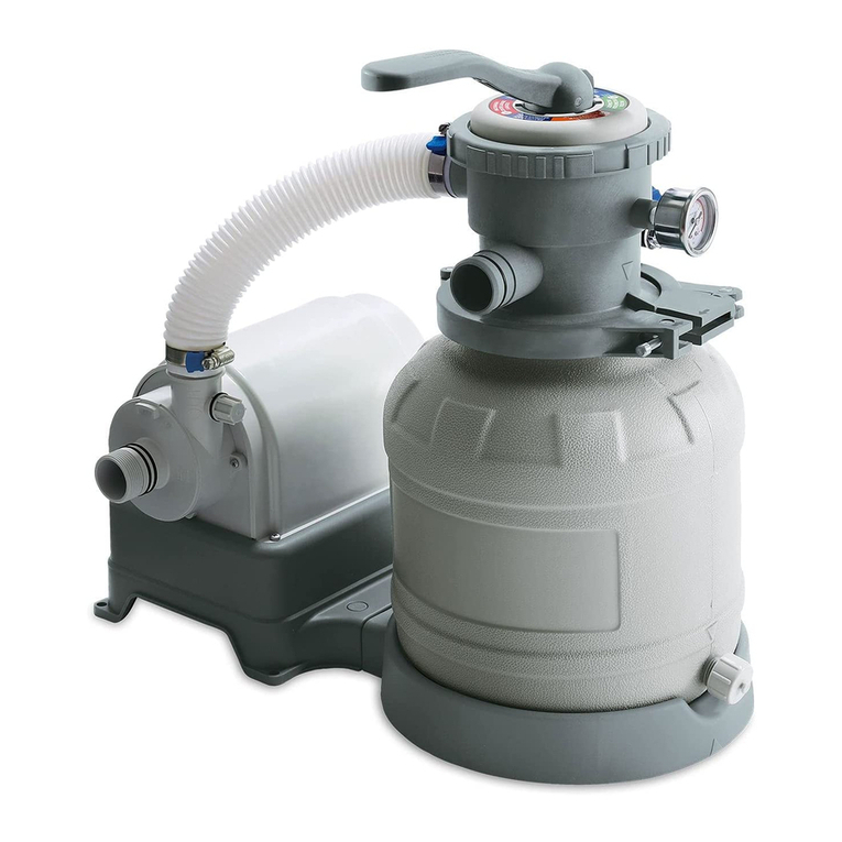
10
OWNER′S MANUAL
EN
2
1
ALIGN
Drain Valve
7. Put the Center Pipe
5
into the Sand Tank
2
. Position the
Center Pipe
5
at the bottom center of the Sand Tank
2
.
8. Place the Sand Guard
6
over the top opening of the Center
Pipe
5
.
6
5
16
17
1
PUSH
Tips: Triangular marks on
the Sand Tank
2
and
the Sand Tank Base
1
.
9. Fill the tank with #20 silica sand ONLY. You can purchase the
sand from your local home improvement or building material stores.
Slowly pour sand into the Sand Tank
2
until the sand level is
between the Min and Max marks on the Center Pipe
5
.
5
2
Sand
2
10
12
5ALIGN
10
9
2
5
10. Remove the Sand Guard
6
and save for future use.
11. Install the 6-Port Valve
q
to the Sand Tank
2
, and ensure if fits
securely into the Center Pipe
5
.
Rotate the Valve so that the Pressure Gauge
e
is aligned with the
Drain Valve.
Drain Valve
Make sure the Gasket
9
is
present at the bottom flange
6
Tips: Triangular marks
on the 6-Port Valve
q
and the Sand Tank
2
.
7
PUSH
12. Place the Clamp
7
around the flange of the 6-Port Valve
q
and Sand Tank
2
.
IMPORTANT: Align the hinge on the Clamp
7
with the ridge
on the flange of the 6-Port Valve
q
.
13. Close the Clamp
7
by pushing the two jaws as close together
as possible.
Cam Handle
Cam Bolt
Cam Handle
14. Pull on the Cam Handle, and insert the Cam Bolt into the opposite
jaw until it locks in place.
15. Hold the Cam Handle with one hand and start turning in
clockwise direction to close the jaws further.
The hinge of Clamp aligned
with the ridge of 6-Port Valve
10
2
7
ALIGN
16. When the Clamp
7
is tightened and no more turns can be
made, flip and push the Cam Handle towards the Sand Tank
2
to secure.
17. Connect the Short Hose
t
between the Pump Outlet and the
6-Port Valve Inlet. Tighten the Hose Clamps
y
with a flat-blade
screwdriver. The sand filter pump is now fully assembled.
15
14
15
6-Port Valve Inlet
Pump Outlet
6-PORT VALVE PARTS LIST
Drain Indicator Gasket
Locking Ring
Valve Handle
Wrench
Valve Gasket
Top Cover O-Ring
Valve Housing
Pressure Gauge
Valve Grate
Gasket
Drain Indicator
6-PORT VALVE SETUP
2. Fit the Gasket in place.
1. Using the Wrench, twist counterclockwise to loosen and remove the Locking Ring.
3. Insert the Top Cover O-Ring into the groove of the Valve Housing.
Valve Gasket Top Cover O-Ring
Valve Housing
4. Insert the Valve Handle into the Valve Housing.
Make sure that
the key aligns
with the keyway.
5. Place the Locking Ring over the Valve Housing. 6. Tighten the Locking Ring with the Wrench.
Locking Ring
Tools required:
Flat-blade screwdriver (not included)
1. Set up the pool by following all the instructions that came with
the pool. Do not fill water until the Filter Pump is properly
installed. Locate the Outlet and Inlet openings on the pool wall.
SETUP INSTRUCTIONS
Inlet
Outlet
WARNING:
CLIMBING HAZZARD! PLEASE PREVENT CHILDREN FROM CLIMBING ON THE FILTRATION SYSTEM TO GAIN ACCESS TO THE POOL.
Before assembling your product, please take a few minutes to check the contents and become familiar with all the parts.
3. Install the Return Fitting
z
on the Inlet opening of the pool.
31
32
30
26
29
28
27
Pool Exterior
Pool Interior
2. Install the Suction Fitting components into the Outlet opening.
24A
24B
23
23
21
21
22
22
25
25
Pool Exterior
Pool Interior
Pool Exterior
Pool Interior
24B
24B
23
23
22
22
25
25
For pump included with the pool:
For pump sold separately:
21
21
6. With the Drain Valve of the Sand Tank
2
pointing outwards,
place the Sand Tank
2
onto the Sand Tank Base
1
.
5. Insert and push the Lock Pins
u
all the way down to
secure the Pump
i
to the Sand Tank Base
1
.
Cam Handle
PUSH
72
FUNCTIONS OF 6-PORT VALVE
Water Flow DirectionValve Handle Position
WASTE
NULL
RECIRCULATE
CLOSED
DO NOT SWITCH
ON THE PUMP
FILTER3
BACKWASH1
RINSE2
Function
Reverses the water flow to wash the sand
Also prevents fine sand from ending up in your pool
ALWAYS remove the Blue Drain Outlet Cap
w
before using this setting,
and replace the cap when done.
* Backwash the sand when the pressure reading is 1-1.5 bar (14.5-21.8
psi) ABOVE the initial pressure OR at least once every 2 weeks.
Continue to backwash until the water from the drain outlet runs clean.
Levels out the sand bed after backwashing
ALWAYS remove the Blue Drain Outlet Cap
w
before using this setting,
and replace the cap when done.
Continue to rinse until the water from the drain outlet runs clean.
Normal filtration and vacuuming of the pool
Recirculates water without filtering
For winterizing and storage
Vacuums water directly to drain and lowers the pool water level
ALWAYS remove the Blue Drain Outlet Cap
w
before using this setting,
and replace the cap when done.
Shuts off the water flow between the sand filter system and the pool
DO NOT SWITCH ON THE PUMP
3RROĺ3XPSĺ6DQG)RUZDUG
ĺ'UDLQ2XWOHW
3RROĺ3XPSĺ6DQG%DFNZDUG
ĺ'UDLQ2XWOHW
3RROĺ3XPSĺ6DQG)RUZDUG
ĺ3RRO
3RROĺ3XPSĺ'UDLQ2XWOHW
3RROĺ3XPSĺ3RRO
Excess water flow
No water flow
DO NOT SWITCH ON THE PUMP
POOL WATER CARE
•
The following items are required to get your pool ready for use. They are available at
polygroupstore.com or your local pool supplies stores:
a. Test kit – for checking the chlorine and pH levels of the pool water
b. Floating chlorine dispenser (not included) and chlorine tablet – for water disinfection
and prevention of the growth of algae
c. pH control chemicals – for adjusting the pH level up (soda ash) or down (acid)
d. Algaecides – to eliminate algae
e. Superchlorinator – to destroy (“shock”) the combined chlorine, ammonia, nitrogen, and
organic compounds that build up in pool water over time and with extended use
f. Leaf net with handle – for removing leaves, trash, insects, etc. from the pool
• IMPORTANT: it is a MUST to maintain the chlorine and pH levels at all times:
a. Check and adjust the pH and chlorine levels daily. FILTER PUMP ALONE WILL NOT
PREVENT ALGAE FROM GROWING IN POOL WATER; THIS CAN ONLY BE
DONE BY MAINTAINING PROPER CHLORINE AND pH LEVELS AT ALL TIMES.
b. Recommended pH level: between 7.3 and 7.8
c. Recommended chlorine level: between 1.0 ppm and 1.6 ppm
d. Superchlorinate your pool at least every other week.
e. Hot weather and heavy use may require the pH and chlorine levels to be maintained on the upper side of the scale as well as a weekly
superchlorination.
f. Using a pool and/or solar cover will help maintain the pH and chlorine levels by reducing evaporation of pool water.
g. CAUTION: High chlorine concentration and low pH level will damage the pool/pool liner. You must follow the instructions on quantity and safe
usage of the pool chemicals you use.
NEVER drop lumps or pellets of chemicals into the pool – this may present a hazard to the swimmers and/or damage your pool liner.
• Clean your pool regularly using a maintenance kit with vacuum. You can get the kit from polygroupstore.com.
• Using a foot bath prior to entering the pool will help keep the pool clean.
•
Avoid using well water. If you must use well water, always seek professional advice from your local pool chemical suppliers before chemicals into it.
• Find out the water capacity (in gallon) of your pool from the pool Owner’s Manual. You will need it to determine the amount of chemicals required,
or when you contact a pool supplies expert for water testing and advice on safe use of chemicals.
NOTE: Always follow the manufacturer label directions of the chemicals you choose to use.
PUMP MOTOR CARE
PUMP MAINTENANCE
• BACKWASH the sand bed when the pressure reading is 1-1.5 bar (14.5 - 21.8 psi) above the initial pressure; or, BACKWASH the sand bed at least
once every TWO weeks.
• Discard all the sand at the end of the season, and wash the pump components, sand tank and 6-port valve thoroughly with fresh water before storage.
Fill up with new sand at the beginning of the swimming season.
• Check the pump output daily. If flow is reduced, see Symptom 3 of TROUBLESHOOTING GUIDE (p. 17).
• Check the pump, hoses and fittings for leaks. If a leak is found, see Symptom 5 & 6 of TROUBLESHOOTING GUIDE.
IMPORTANT! This Sand Filter Pump is protected by a thermal switch, a safety device that stops the pump from running when it is overheated, to
prevent damage to the pump and prolong its service life. If your pump turns off automatically, it’s likely the pool water temperature is too high or the
water flow through the pump is insufficient for cooling down the pump. Check and correct the water flow, and let the motor cool down for at least 15
minutes. The pump will restart automatically after the motor is completely cooled down. If the display screen of the GFCI plug shows "0", press the
"SET" button to restart the pump. You could also operate the pump at night when the temperature is lower. If the pump turns off automatically again,
inspect if the rotor is blocked by dirt.
TROUBLESHOOTING GUIDE
WARNING: TURN OFF THE PUMP AND UNPLUG THE POWER CORD BEFORE TROUBLESHOOTING THE FILTER PUMP.
WINTERIZING, DISASSEMBLY & STORAGE
1. First, unplug the Power Cord Set 4of the system.
2. Loosen all Hose Clamps y. Remove the Hose rtand allow water to drain.
3. Remove Drain Valve Cap 3from the Sand Tank 2and allow water to drain. Replace and tighten the Drain Valve Cap 3.
4. Clear and lubricate all Fitting O-Rings owith petroleum jelly.
5. Turn the 6-Port Valve Handle ato "NULL" position.
6. Allow the sand filter pump to dry completely. Store the sand filter pump in a cool and dry location away from direct sun light.
7. All items should be stored in a dry environment that remains above 32 degrees Fahrenheit at all times.
USE OF PUMP
1. Make sure the pump is switched OFF.
2. Plug the Power Cord Set
4
to a grounded receptacle.
3. BACKWASH the sand:
ALWAYS BACKWASH THE SAND BEFORE FILTERING. This prevents fine sand from going
through the pump and then to the pool, meanwhile washes off the dirt and debris of the sand.
a. Remove the Blue Drain Outlet Cap
w
.
(Optionally, connect a 1.5” [38mm] hose to the drain outlet to direct the waste water to a nearby drain)
b. Press down the 6-Port Valve Handle
a
and turn it to BACKWASH.
c. Switch the pump on.
Refer to "GFCI Plug Instructions" (p. 16) for the operating instructions with GFCI plug.
The water should now be circulating backward through the sand bed to the drain outlet. Continue to
BACKWASH until the drain water runs clear, or the Drain Indicator
p
shows clear water.
d. Switch the pump off.
4. RINSE the sand:
The RINSE function will clean up and level out the sand bed after each BACKWASHING.
a. Press down the 6-Port Valve Handle
a
and turn it to RINSE.
b. Switch the pump on.
RINSE for ONE MINUTE, then switch the pump off.
c. Put back and retighten the Blue Drain Outlet Cap
w
.
5. FILTER the pool:
a. Press the 6-Port Valve Handle
a
down and turn it to FILTER.
b. Switch the pump on.
c. Jot down the sand tank pressure reading of Pressure Gauge
e
. This reading indicates the
“initial pressure”, meaning the tank pressure when the sand bed is clean. Backwash the sand bed whenever the reading is 1-1.5 bar (14.5-21.8 psi) above
the initial pressure, or once every TWO weeks to maintain water cleanliness.
6. To turn off the pump, press the power switch to OFF and unplug Power Cord Set
4
.
11
12
20
19
USE OF PUMP
Before using the Pump
IMPORTANT:
1. Make sure to press the pump power switch to OFF before plugging the Power Cord Set
4
into a power outlet.
2. Always PRESS DOWN the 6-Port Valve Handle
a
BEFORE switching handle positions.
3. Always BACKWASH the sand before filtering. This prevents fine sand from going through the pump and then to
the pool, meanwhile washes off the dirt and debris of the sand.
4. Make sure that the Hoses
r
t
are firmly secured to the fittings on the pump and the pool.
5. Fill the pool with water up to the FILL LINE. Do NOT dry run the filter pump.
6. FILTER PUMP ALONE WILL NOT PREVENT ALGAE FROM GROWING IN POOL WATER;
THIS CAN ONLY BE DONE BY MAINTAINING PROPER CHLORINE AND pH LEVELS AT ALL TIMES.
For details, see POOL WATER CARE (p. 17).
1. Locate a grounded receptacle at least 15 feet (4.5 m) away from the pool.
2. To turn on the Pump, plug in the GFCI power cord set
4
to the power outlet.
3. The GFCI power cord set
4
comes with a pre-set timer function.
a. Default timer setting: When the power is on, the display screen shows “10”, indicating that the default operating
time of the pump is 10 hours. The pump will automatically turn off after the 10 hours and will remain off for 14 hours. This
is based on a 24-hour cycle. This cycle will then continue as long as the power is on.
b. Time adjustment: Press the "SET" button to set the desired operating time of the pump between 1 to 10 hours,
with each press adjusts the time by 1 hour. For example, when the display screen on the plug shows “05”, the pump will
work for 5 hours and restart after a 19 hours break.
c. If the display screen shows "0", it indicates that the pre-set working time has ended and the pump is currently off.
d. To restart the pump earlier than the pre-set time, press the “SET” button.
In this case, the pre-set working time will adjust by 1 hour from the previous setting.
4. To turn off the pump, press the “TEST” button of the GFCI Plug, and unplug it from the power outlet.
If you accidentally press the “TEST” button while the pump is working, you can press the “RESET” button to restore the pump to work.
GFCI Plug with
Timer Function
*Do not connect to
another timer device
4
5. From inside the pool, check if the water flow from the Return Fitting
z
is correct. It should feel like a solid stream of water returning to the pool. If not, or if you
feel a reduction in flow, see Symptom 3 of the TROUBLESHOOTING GUIDE (p. 18).
6. IMPORTANT: Check and adjust the pH and chlorine levels daily. FILTER PUMP ALONE WILL NOT PREVENT ALGAE FROM GROWING IN POOL WATER;
THIS CAN ONLY BE DONE BY MAINTAINING PROPER CHLORINE AND pH LEVELS AT ALL TIMES. For details, see POOL WATER CARE (p. 17).
“RESET” button:
• When the display screen shows a number between "01” to “10", but the pump is not operating (e.g. the "TEST" button is pressed
while the pump is working), press the "RESET" button to restore the pump to work.
• When the display screen shows "0" and the pump has stopped working, pressing the "RESET" button will have no action.
“TEST” button:
• To test the GFCI’s leakage protection function: Plug the GFCI power cord set into the power outlet, make sure the pump is in
working mode (i.e. display screen of the GFCI plug IS NOT showing “0”). Push the “TEST” button, the power to the pump should
be interrupted by the GFCI and the pump will stop working.
• When the display screen shows "0" and the pump has stopped working, pressing the "TEST" button will have no action.
“SET” button:
• Press the "SET" button to select the desired operating time of the pump between 1 to 10 hours, with each press adjusts the time
by 1 hour.
• If the display screen shows "0", press the "SET" button will restart the pump. In this case, the pre-set operating time will be adjusted
by 1 hour from the previous setting.
Note: If you find the time interval available for selection is less than 10 hours, it could be the memory setting from the previous
cycle. Disconnect the power supply of the GFCI plug and reconnect again, and it will revert back to the default 10 hours range.
Display Screen:
• Shows “01”, “02”…to “10” to represent the pre-set working time when the GFCI power cord set is plugged into a power outlet.
• Shows "0” when the pump is in off mode.
Description of GFCI Plug with Timer Function
TEST
SET
RESET
GFCI PLUG INSTRUCTIONS
Problem Cause Solution
1. The Pump motor
fails to start
2. The Sand Filter
doesn’t clean
the pool
3. The Sand Filter
doesn’t pump
water, or the
flow is very slow
4. The Pump doesn’t
work
5. The 6-Port Valve q
or its locking ring is
leaking
6. Leakage at
Hoses rt
7. Pressure Gauge e
doesn’t work
8. Sand ended up in
the pool
A. The Pump not plugged in OR the
Power Cord Set 4not activated
B. Low voltage
C. The Power Cord Set 4and/or circuit
breaker tripped
D. The Pump motor is too hot, and the thermal
safety switch shut it off
A. Clogged Suction Fitting dor inlet of
the Pump
B. An air leak on the intake Hose r
C. The sand is too dirty
D. Crusting or caking of sand surface
A. Low water level
B. Clogged Suction Fitting dstrainer
C. An air leak on the intake Hose r
D. Faulty motor or the impeller is jammed
A. The Gasket 9is missing
B. The Gasket 9is dirty
C. Loose Hose Clamps y
D. Faulty 6-Port Valve
A1. The connection between the
Suction Fitting d& the Suction
Fitting Lock Nut
24A
/
24B
A2. The connection between the
Suction d/ Return zFittings
and the Hose r
B. The O-Rings oof Hose connections
are missing
A. Clogged inlet of the Pressure Gauge
B. Faulty Pressure Gauge
A. The sand is too small for the Pump
B. The sand bed is calcified
E. A pool vacuuming device is attached to
the Pump
A. Inadequate chlorine or pH level
B. No sand in the Sand Tank 2
C. Wrong 6-Port Valve qsetting
D. The pool is too dirty
E. Clogged Suction Fitting d
A. Plug the GFCI Power Cord Set to a 3-wire grounded power outlet, then press the
RESET button to start the Pump.
B. Check and make sure the line voltage is between 105VAC and 125VAC.
C. If problem persists, have the circuit checked by a qualified electrician.
D. Let the motor cool down and restart the Pump.
A. Clean the Suction Fitting and the Hose rconnecting it to the Pump inlet.
B. Check the Hose for damage; tighten the Hose Clamps y, and check
the pool water level.
C. Backwash the sand more frequently.
D. Replace about 1” (25mm) of the sand, or all the sand if problem persists.
A. Fill water up to the FILL LINE marked on the pool wall.
B. Clean the strainer.
C. Check the Hose for damage; tighten the Hose Clamps y, and check
the pool water level.
D. Contact our Customer Service.
A. Remove the 6-Port Valve qand check to ensure the Gasket is in place.
B. Clean the Gasket with garden hose water.
C. Tighten/reinstall the Clamps.
D. Contact our Customer Service.
B. Ensure that the O-Rings are in place and intact.
A. Unscrew and remove the Gauge, then clear any obstructions in its inlet.
B. Contact our Customer Service.
A. Use only #20 grade silica sand with particle size range 0.45-0.85 mm
(0.018-0.033 inches) and uniformity coefficient less than 1.75
B. Discard all the used sand and replace with new sand.
E. Remove the device.
A. Adjust the chlorine and pH levels. Consult your local pool supplies stores.
B. Fill sand in as per SETUP INSTRUCTIONS (8)-(10) on p. 10-11.
C. Set the Valve Handle ato “FILTER” position.
D. Run the Pump longer.
E. Clean the strainer of the Suction Fitting.
A2. Check that the Hose Clamps yare properly secured over both the
Hoses rand their O-rings o; adjust and re-tighten if necessary. Also,
check the Hoses for cracks or holes and replace as needed.
A1. Check the connection between Suction Fitting dand the Suction Fitting
Lock Nut
24A
/
24B
. If a loose or unbalanced connection is found, re-tighten the
Suction Fitting dwith the Suction Fitting Lock Nut
24A
/
24B
, make sure they
are screwed tightly.
Note: Water may still drip out from the connection after the lock nut is
re-tightened. There could be water trapped within the connection of the
lock nut from before. Simply let the residue water drip out. This may
take a few hours for the connection to be completely dry.
18. Connect the Pump Inlet to the Pool Outlet as follows:
For pump included with the pool:
Turn the Split Suction Fitting Lock Nut with one end facing downwards, then connect this end to the Pump inlet with a Hose and one Clamp
on each end. Connect the other end of the Split Suction Fitting Lock Nut to the Solo Suction Fitting Lock Nut with another hose.
For pump sold separately:
Connect each of the Solo Suction Fitting Lock Nut with one Hose and one Clamp respectively. Then, connect the other end of the two hoses
w
ith the Y-Shaped Hose Connector /. Connect the open end of the Y-Shaped Hose Connector /to the Pump inlet with one Hose and one Clamp.
19. Connect the 6-Port Valve Outlet to the RF 90° Elbow
j
of the Return Fitting Set with another Hose and one Clamp on each end.
24A
24A
24B
24B
r
t
h
20. Make sure the Hose Clamps
y
seal tightly over both the Hose
r
and O-Rings
o
. Tighten all the Clamps with a flat-blade screwdriver.
For pump included with the pool: For pump sold separately:
24B
15
13A
15
15
24A
24A 24B
13A
13A
13B
13A
13B 24B
13B 13B
26
15
26
15
26
24B
15
15 39
26
4. Snap the Pump
i
on to the Sand Tank Base
1
.
5
2
17
1
11
EN
2
1
ALIGN
Drain Valve
7. Put the Center Pipe
5
into the Sand Tank
2
. Position the
Center Pipe
5
at the bottom center of the Sand Tank
2
.
8. Place the Sand Guard
6
over the top opening of the Center
Pipe
5
.
6
5
16
17
1
PUSH
Tips: Triangular marks on
the Sand Tank
2
and
the Sand Tank Base
1
.
9. Fill the tank with #20 silica sand ONLY. You can purchase the
sand from your local home improvement or building material stores.
Slowly pour sand into the Sand Tank
2
until the sand level is
between the Min and Max marks on the Center Pipe
5
.
5
2
Sand
2
10
12
5ALIGN
10
9
2
5
10. Remove the Sand Guard
6
and save for future use.
11. Install the 6-Port Valve
q
to the Sand Tank
2
, and ensure if fits
securely into the Center Pipe
5
.
Rotate the Valve so that the Pressure Gauge
e
is aligned with the
Drain Valve.
Drain Valve
Make sure the Gasket
9
is
present at the bottom flange
6
Tips: Triangular marks
on the 6-Port Valve
q
and the Sand Tank
2
.
7
PUSH
12. Place the Clamp
7
around the flange of the 6-Port Valve
q
and Sand Tank
2
.
IMPORTANT: Align the hinge on the Clamp
7
with the ridge
on the flange of the 6-Port Valve
q
.
13. Close the Clamp
7
by pushing the two jaws as close together
as possible.
Cam Handle
Cam Bolt
Cam Handle
14. Pull on the Cam Handle, and insert the Cam Bolt into the opposite
jaw until it locks in place.
15. Hold the Cam Handle with one hand and start turning in
clockwise direction to close the jaws further.
The hinge of Clamp aligned
with the ridge of 6-Port Valve
10
2
7
ALIGN
16. When the Clamp
7
is tightened and no more turns can be
made, flip and push the Cam Handle towards the Sand Tank
2
to secure.
17. Connect the Short Hose
t
between the Pump Outlet and the
6-Port Valve Inlet. Tighten the Hose Clamps
y
with a flat-blade
screwdriver. The sand filter pump is now fully assembled.
15
14
15
6-Port Valve Inlet
Pump Outlet
6-PORT VALVE PARTS LIST
Drain Indicator Gasket
Locking Ring
Valve Handle
Wrench
Valve Gasket
Top Cover O-Ring
Valve Housing
Pressure Gauge
Valve Grate
Gasket
Drain Indicator
6-PORT VALVE SETUP
2. Fit the Gasket in place.
1. Using the Wrench, twist counterclockwise to loosen and remove the Locking Ring.
3. Insert the Top Cover O-Ring into the groove of the Valve Housing.
Valve Gasket Top Cover O-Ring
Valve Housing
4. Insert the Valve Handle into the Valve Housing.
Make sure that
the key aligns
with the keyway.
5. Place the Locking Ring over the Valve Housing. 6. Tighten the Locking Ring with the Wrench.
Locking Ring
Tools required:
Flat-blade screwdriver (not included)
1. Set up the pool by following all the instructions that came with
the pool. Do not fill water until the Filter Pump is properly
installed. Locate the Outlet and Inlet openings on the pool wall.
SETUP INSTRUCTIONS
Inlet
Outlet
WARNING:
CLIMBING HAZZARD! PLEASE PREVENT CHILDREN FROM CLIMBING ON THE FILTRATION SYSTEM TO GAIN ACCESS TO THE POOL.
Before assembling your product, please take a few minutes to check the contents and become familiar with all the parts.
3. Install the Return Fitting
z
on the Inlet opening of the pool.
31
32
30
26
29
28
27
Pool Exterior
Pool Interior
2. Install the Suction Fitting components into the Outlet opening.
24A
24B
23
23
21
21
22
22
25
25
Pool Exterior
Pool Interior
Pool Exterior
Pool Interior
24B
24B
23
23
22
22
25
25
For pump included with the pool:
For pump sold separately:
21
21
6. With the Drain Valve of the Sand Tank
2
pointing outwards,
place the Sand Tank
2
onto the Sand Tank Base
1
.
5. Insert and push the Lock Pins
u
all the way down to
secure the Pump
i
to the Sand Tank Base
1
.
Cam Handle
PUSH
72
FUNCTIONS OF 6-PORT VALVE
Water Flow DirectionValve Handle Position
WASTE
NULL
RECIRCULATE
CLOSED
DO NOT SWITCH
ON THE PUMP
FILTER3
BACKWASH1
RINSE2
Function
Reverses the water flow to wash the sand
Also prevents fine sand from ending up in your pool
ALWAYS remove the Blue Drain Outlet Cap
w
before using this setting,
and replace the cap when done.
* Backwash the sand when the pressure reading is 1-1.5 bar (14.5-21.8
psi) ABOVE the initial pressure OR at least once every 2 weeks.
Continue to backwash until the water from the drain outlet runs clean.
Levels out the sand bed after backwashing
ALWAYS remove the Blue Drain Outlet Cap
w
before using this setting,
and replace the cap when done.
Continue to rinse until the water from the drain outlet runs clean.
Normal filtration and vacuuming of the pool
Recirculates water without filtering
For winterizing and storage
Vacuums water directly to drain and lowers the pool water level
ALWAYS remove the Blue Drain Outlet Cap
w
before using this setting,
and replace the cap when done.
Shuts off the water flow between the sand filter system and the pool
DO NOT SWITCH ON THE PUMP
3RROĺ3XPSĺ6DQG)RUZDUG
ĺ'UDLQ2XWOHW
3RROĺ3XPSĺ6DQG%DFNZDUG
ĺ'UDLQ2XWOHW
3RROĺ3XPSĺ6DQG)RUZDUG
ĺ3RRO
3RROĺ3XPSĺ'UDLQ2XWOHW
3RROĺ3XPSĺ3RRO
Excess water flow
No water flow
DO NOT SWITCH ON THE PUMP
POOL WATER CARE
•
The following items are required to get your pool ready for use. They are available at
polygroupstore.com or your local pool supplies stores:
a. Test kit – for checking the chlorine and pH levels of the pool water
b. Floating chlorine dispenser (not included) and chlorine tablet – for water disinfection
and prevention of the growth of algae
c. pH control chemicals – for adjusting the pH level up (soda ash) or down (acid)
d. Algaecides – to eliminate algae
e. Superchlorinator – to destroy (“shock”) the combined chlorine, ammonia, nitrogen, and
organic compounds that build up in pool water over time and with extended use
f. Leaf net with handle – for removing leaves, trash, insects, etc. from the pool
• IMPORTANT: it is a MUST to maintain the chlorine and pH levels at all times:
a. Check and adjust the pH and chlorine levels daily. FILTER PUMP ALONE WILL NOT
PREVENT ALGAE FROM GROWING IN POOL WATER; THIS CAN ONLY BE
DONE BY MAINTAINING PROPER CHLORINE AND pH LEVELS AT ALL TIMES.
b. Recommended pH level: between 7.3 and 7.8
c. Recommended chlorine level: between 1.0 ppm and 1.6 ppm
d. Superchlorinate your pool at least every other week.
e. Hot weather and heavy use may require the pH and chlorine levels to be maintained on the upper side of the scale as well as a weekly
superchlorination.
f. Using a pool and/or solar cover will help maintain the pH and chlorine levels by reducing evaporation of pool water.
g. CAUTION: High chlorine concentration and low pH level will damage the pool/pool liner. You must follow the instructions on quantity and safe
usage of the pool chemicals you use.
NEVER drop lumps or pellets of chemicals into the pool – this may present a hazard to the swimmers and/or damage your pool liner.
• Clean your pool regularly using a maintenance kit with vacuum. You can get the kit from polygroupstore.com.
• Using a foot bath prior to entering the pool will help keep the pool clean.
•
Avoid using well water. If you must use well water, always seek professional advice from your local pool chemical suppliers before chemicals into it.
• Find out the water capacity (in gallon) of your pool from the pool Owner’s Manual. You will need it to determine the amount of chemicals required,
or when you contact a pool supplies expert for water testing and advice on safe use of chemicals.
NOTE: Always follow the manufacturer label directions of the chemicals you choose to use.
PUMP MOTOR CARE
PUMP MAINTENANCE
• BACKWASH the sand bed when the pressure reading is 1-1.5 bar (14.5 - 21.8 psi) above the initial pressure; or, BACKWASH the sand bed at least
once every TWO weeks.
• Discard all the sand at the end of the season, and wash the pump components, sand tank and 6-port valve thoroughly with fresh water before storage.
Fill up with new sand at the beginning of the swimming season.
• Check the pump output daily. If flow is reduced, see Symptom 3 of TROUBLESHOOTING GUIDE (p. 17).
• Check the pump, hoses and fittings for leaks. If a leak is found, see Symptom 5 & 6 of TROUBLESHOOTING GUIDE.
IMPORTANT! This Sand Filter Pump is protected by a thermal switch, a safety device that stops the pump from running when it is overheated, to
prevent damage to the pump and prolong its service life. If your pump turns off automatically, it’s likely the pool water temperature is too high or the
water flow through the pump is insufficient for cooling down the pump. Check and correct the water flow, and let the motor cool down for at least 15
minutes. The pump will restart automatically after the motor is completely cooled down. If the display screen of the GFCI plug shows "0", press the
"SET" button to restart the pump. You could also operate the pump at night when the temperature is lower. If the pump turns off automatically again,
inspect if the rotor is blocked by dirt.
TROUBLESHOOTING GUIDE
WARNING: TURN OFF THE PUMP AND UNPLUG THE POWER CORD BEFORE TROUBLESHOOTING THE FILTER PUMP.
WINTERIZING, DISASSEMBLY & STORAGE
1. First, unplug the Power Cord Set 4of the system.
2. Loosen all Hose Clamps y. Remove the Hose rtand allow water to drain.
3. Remove Drain Valve Cap 3from the Sand Tank 2and allow water to drain. Replace and tighten the Drain Valve Cap 3.
4. Clear and lubricate all Fitting O-Rings owith petroleum jelly.
5. Turn the 6-Port Valve Handle ato "NULL" position.
6. Allow the sand filter pump to dry completely. Store the sand filter pump in a cool and dry location away from direct sun light.
7. All items should be stored in a dry environment that remains above 32 degrees Fahrenheit at all times.
USE OF PUMP
1. Make sure the pump is switched OFF.
2. Plug the Power Cord Set
4
to a grounded receptacle.
3. BACKWASH the sand:
ALWAYS BACKWASH THE SAND BEFORE FILTERING. This prevents fine sand from going
through the pump and then to the pool, meanwhile washes off the dirt and debris of the sand.
a. Remove the Blue Drain Outlet Cap
w
.
(Optionally, connect a 1.5” [38mm] hose to the drain outlet to direct the waste water to a nearby drain)
b. Press down the 6-Port Valve Handle
a
and turn it to BACKWASH.
c. Switch the pump on.
Refer to "GFCI Plug Instructions" (p. 16) for the operating instructions with GFCI plug.
The water should now be circulating backward through the sand bed to the drain outlet. Continue to
BACKWASH until the drain water runs clear, or the Drain Indicator
p
shows clear water.
d. Switch the pump off.
4. RINSE the sand:
The RINSE function will clean up and level out the sand bed after each BACKWASHING.
a. Press down the 6-Port Valve Handle
a
and turn it to RINSE.
b. Switch the pump on.
RINSE for ONE MINUTE, then switch the pump off.
c. Put back and retighten the Blue Drain Outlet Cap
w
.
5. FILTER the pool:
a. Press the 6-Port Valve Handle
a
down and turn it to FILTER.
b. Switch the pump on.
c. Jot down the sand tank pressure reading of Pressure Gauge
e
. This reading indicates the
“initial pressure”, meaning the tank pressure when the sand bed is clean. Backwash the sand bed whenever the reading is 1-1.5 bar (14.5-21.8 psi) above
the initial pressure, or once every TWO weeks to maintain water cleanliness.
6. To turn off the pump, press the power switch to OFF and unplug Power Cord Set
4
.
11
12
20
19
USE OF PUMP
Before using the Pump
IMPORTANT:
1. Make sure to press the pump power switch to OFF before plugging the Power Cord Set
4
into a power outlet.
2. Always PRESS DOWN the 6-Port Valve Handle
a
BEFORE switching handle positions.
3. Always BACKWASH the sand before filtering. This prevents fine sand from going through the pump and then to
the pool, meanwhile washes off the dirt and debris of the sand.
4. Make sure that the Hoses
r
t
are firmly secured to the fittings on the pump and the pool.
5. Fill the pool with water up to the FILL LINE. Do NOT dry run the filter pump.
6. FILTER PUMP ALONE WILL NOT PREVENT ALGAE FROM GROWING IN POOL WATER;
THIS CAN ONLY BE DONE BY MAINTAINING PROPER CHLORINE AND pH LEVELS AT ALL TIMES.
For details, see POOL WATER CARE (p. 17).
1. Locate a grounded receptacle at least 15 feet (4.5 m) away from the pool.
2. To turn on the Pump, plug in the GFCI power cord set
4
to the power outlet.
3. The GFCI power cord set
4
comes with a pre-set timer function.
a. Default timer setting: When the power is on, the display screen shows “10”, indicating that the default operating
time of the pump is 10 hours. The pump will automatically turn off after the 10 hours and will remain off for 14 hours. This
is based on a 24-hour cycle. This cycle will then continue as long as the power is on.
b. Time adjustment: Press the "SET" button to set the desired operating time of the pump between 1 to 10 hours,
with each press adjusts the time by 1 hour. For example, when the display screen on the plug shows “05”, the pump will
work for 5 hours and restart after a 19 hours break.
c. If the display screen shows "0", it indicates that the pre-set working time has ended and the pump is currently off.
d. To restart the pump earlier than the pre-set time, press the “SET” button.
In this case, the pre-set working time will adjust by 1 hour from the previous setting.
4. To turn off the pump, press the “TEST” button of the GFCI Plug, and unplug it from the power outlet.
If you accidentally press the “TEST” button while the pump is working, you can press the “RESET” button to restore the pump to work.
GFCI Plug with
Timer Function
*Do not connect to
another timer device
4
5. From inside the pool, check if the water flow from the Return Fitting
z
is correct. It should feel like a solid stream of water returning to the pool. If not, or if you
feel a reduction in flow, see Symptom 3 of the TROUBLESHOOTING GUIDE (p. 18).
6. IMPORTANT: Check and adjust the pH and chlorine levels daily. FILTER PUMP ALONE WILL NOT PREVENT ALGAE FROM GROWING IN POOL WATER;
THIS CAN ONLY BE DONE BY MAINTAINING PROPER CHLORINE AND pH LEVELS AT ALL TIMES. For details, see POOL WATER CARE (p. 17).
“RESET” button:
• When the display screen shows a number between "01” to “10", but the pump is not operating (e.g. the "TEST" button is pressed
while the pump is working), press the "RESET" button to restore the pump to work.
• When the display screen shows "0" and the pump has stopped working, pressing the "RESET" button will have no action.
“TEST” button:
• To test the GFCI’s leakage protection function: Plug the GFCI power cord set into the power outlet, make sure the pump is in
working mode (i.e. display screen of the GFCI plug IS NOT showing “0”). Push the “TEST” button, the power to the pump should
be interrupted by the GFCI and the pump will stop working.
• When the display screen shows "0" and the pump has stopped working, pressing the "TEST" button will have no action.
“SET” button:
• Press the "SET" button to select the desired operating time of the pump between 1 to 10 hours, with each press adjusts the time
by 1 hour.
• If the display screen shows "0", press the "SET" button will restart the pump. In this case, the pre-set operating time will be adjusted
by 1 hour from the previous setting.
Note: If you find the time interval available for selection is less than 10 hours, it could be the memory setting from the previous
cycle. Disconnect the power supply of the GFCI plug and reconnect again, and it will revert back to the default 10 hours range.
Display Screen:
• Shows “01”, “02”…to “10” to represent the pre-set working time when the GFCI power cord set is plugged into a power outlet.
• Shows "0” when the pump is in off mode.
Description of GFCI Plug with Timer Function
TEST
SET
RESET
GFCI PLUG INSTRUCTIONS
Problem Cause Solution
1. The Pump motor
fails to start
2. The Sand Filter
doesn’t clean
the pool
3. The Sand Filter
doesn’t pump
water, or the
flow is very slow
4. The Pump doesn’t
work
5. The 6-Port Valve q
or its locking ring is
leaking
6. Leakage at
Hoses rt
7. Pressure Gauge e
doesn’t work
8. Sand ended up in
the pool
A. The Pump not plugged in OR the
Power Cord Set 4not activated
B. Low voltage
C. The Power Cord Set 4and/or circuit
breaker tripped
D. The Pump motor is too hot, and the thermal
safety switch shut it off
A. Clogged Suction Fitting dor inlet of
the Pump
B. An air leak on the intake Hose r
C. The sand is too dirty
D. Crusting or caking of sand surface
A. Low water level
B. Clogged Suction Fitting dstrainer
C. An air leak on the intake Hose r
D. Faulty motor or the impeller is jammed
A. The Gasket 9is missing
B. The Gasket 9is dirty
C. Loose Hose Clamps y
D. Faulty 6-Port Valve
A1. The connection between the
Suction Fitting d& the Suction
Fitting Lock Nut
24A
/
24B
A2. The connection between the
Suction d/ Return zFittings
and the Hose r
B. The O-Rings oof Hose connections
are missing
A. Clogged inlet of the Pressure Gauge
B. Faulty Pressure Gauge
A. The sand is too small for the Pump
B. The sand bed is calcified
E. A pool vacuuming device is attached to
the Pump
A. Inadequate chlorine or pH level
B. No sand in the Sand Tank 2
C. Wrong 6-Port Valve qsetting
D. The pool is too dirty
E. Clogged Suction Fitting d
A. Plug the GFCI Power Cord Set to a 3-wire grounded power outlet, then press the
RESET button to start the Pump.
B. Check and make sure the line voltage is between 105VAC and 125VAC.
C. If problem persists, have the circuit checked by a qualified electrician.
D. Let the motor cool down and restart the Pump.
A. Clean the Suction Fitting and the Hose rconnecting it to the Pump inlet.
B. Check the Hose for damage; tighten the Hose Clamps y, and check
the pool water level.
C. Backwash the sand more frequently.
D. Replace about 1” (25mm) of the sand, or all the sand if problem persists.
A. Fill water up to the FILL LINE marked on the pool wall.
B. Clean the strainer.
C. Check the Hose for damage; tighten the Hose Clamps y, and check
the pool water level.
D. Contact our Customer Service.
A. Remove the 6-Port Valve qand check to ensure the Gasket is in place.
B. Clean the Gasket with garden hose water.
C. Tighten/reinstall the Clamps.
D. Contact our Customer Service.
B. Ensure that the O-Rings are in place and intact.
A. Unscrew and remove the Gauge, then clear any obstructions in its inlet.
B. Contact our Customer Service.
A. Use only #20 grade silica sand with particle size range 0.45-0.85 mm
(0.018-0.033 inches) and uniformity coefficient less than 1.75
B. Discard all the used sand and replace with new sand.
E. Remove the device.
A. Adjust the chlorine and pH levels. Consult your local pool supplies stores.
B. Fill sand in as per SETUP INSTRUCTIONS (8)-(10) on p. 10-11.
C. Set the Valve Handle ato “FILTER” position.
D. Run the Pump longer.
E. Clean the strainer of the Suction Fitting.
A2. Check that the Hose Clamps yare properly secured over both the
Hoses rand their O-rings o; adjust and re-tighten if necessary. Also,
check the Hoses for cracks or holes and replace as needed.
A1. Check the connection between Suction Fitting dand the Suction Fitting
Lock Nut
24A
/
24B
. If a loose or unbalanced connection is found, re-tighten the
Suction Fitting dwith the Suction Fitting Lock Nut
24A
/
24B
, make sure they
are screwed tightly.
Note: Water may still drip out from the connection after the lock nut is
re-tightened. There could be water trapped within the connection of the
lock nut from before. Simply let the residue water drip out. This may
take a few hours for the connection to be completely dry.
18. Connect the Pump Inlet to the Pool Outlet as follows:
For pump included with the pool:
Turn the Split Suction Fitting Lock Nut with one end facing downwards, then connect this end to the Pump inlet with a Hose and one Clamp
on each end. Connect the other end of the Split Suction Fitting Lock Nut to the Solo Suction Fitting Lock Nut with another hose.
For pump sold separately:
Connect each of the Solo Suction Fitting Lock Nut with one Hose and one Clamp respectively. Then, connect the other end of the two hoses
w
ith the Y-Shaped Hose Connector /. Connect the open end of the Y-Shaped Hose Connector /to the Pump inlet with one Hose and one Clamp.
19. Connect the 6-Port Valve Outlet to the RF 90° Elbow
j
of the Return Fitting Set with another Hose and one Clamp on each end.
24A
24A
24B
24B
r
t
h
20. Make sure the Hose Clamps
y
seal tightly over both the Hose
r
and O-Rings
o
. Tighten all the Clamps with a flat-blade screwdriver.
For pump included with the pool: For pump sold separately:
24B
15
13A
15
15
24A
24A 24B
13A
13A
13B
13A
13B 24B
13B 13B
26
15
26
15
26
24B
15
15 39
26
4. Snap the Pump
i
on to the Sand Tank Base
1
. 5
2
17
1
12
OWNER′S MANUAL
EN
2
1
ALIGN
Drain Valve
7. Put the Center Pipe
5
into the Sand Tank
2
. Position the
Center Pipe
5
at the bottom center of the Sand Tank
2
.
8. Place the Sand Guard
6
over the top opening of the Center
Pipe
5
.
6
5
16
17
1
PUSH
Tips: Triangular marks on
the Sand Tank
2
and
the Sand Tank Base
1
.
9. Fill the tank with #20 silica sand ONLY. You can purchase the
sand from your local home improvement or building material stores.
Slowly pour sand into the Sand Tank
2
until the sand level is
between the Min and Max marks on the Center Pipe
5
.
5
2
Sand
2
10
12
5ALIGN
10
9
2
5
10. Remove the Sand Guard
6
and save for future use.
11. Install the 6-Port Valve
q
to the Sand Tank
2
, and ensure if fits
securely into the Center Pipe
5
.
Rotate the Valve so that the Pressure Gauge
e
is aligned with the
Drain Valve.
Drain Valve
Make sure the Gasket
9
is
present at the bottom flange
6
Tips: Triangular marks
on the 6-Port Valve
q
and the Sand Tank
2
.
7
PUSH
12. Place the Clamp
7
around the flange of the 6-Port Valve
q
and Sand Tank
2
.
IMPORTANT: Align the hinge on the Clamp
7
with the ridge
on the flange of the 6-Port Valve
q
.
13. Close the Clamp
7
by pushing the two jaws as close together
as possible.
Cam Handle
Cam Bolt
Cam Handle
14. Pull on the Cam Handle, and insert the Cam Bolt into the opposite
jaw until it locks in place.
15. Hold the Cam Handle with one hand and start turning in
clockwise direction to close the jaws further.
The hinge of Clamp aligned
with the ridge of 6-Port Valve
10
2
7
ALIGN
16. When the Clamp
7
is tightened and no more turns can be
made, flip and push the Cam Handle towards the Sand Tank
2
to secure.
17. Connect the Short Hose
t
between the Pump Outlet and the
6-Port Valve Inlet. Tighten the Hose Clamps
y
with a flat-blade
screwdriver. The sand filter pump is now fully assembled.
15
14
15
6-Port Valve Inlet
Pump Outlet
6-PORT VALVE PARTS LIST
Drain Indicator Gasket
Locking Ring
Valve Handle
Wrench
Valve Gasket
Top Cover O-Ring
Valve Housing
Pressure Gauge
Valve Grate
Gasket
Drain Indicator
6-PORT VALVE SETUP
2. Fit the Gasket in place.
1. Using the Wrench, twist counterclockwise to loosen and remove the Locking Ring.
3. Insert the Top Cover O-Ring into the groove of the Valve Housing.
Valve Gasket Top Cover O-Ring
Valve Housing
4. Insert the Valve Handle into the Valve Housing.
Make sure that
the key aligns
with the keyway.
5. Place the Locking Ring over the Valve Housing. 6. Tighten the Locking Ring with the Wrench.
Locking Ring
Tools required:
Flat-blade screwdriver (not included)
1. Set up the pool by following all the instructions that came with
the pool. Do not fill water until the Filter Pump is properly
installed. Locate the Outlet and Inlet openings on the pool wall.
SETUP INSTRUCTIONS
Inlet
Outlet
WARNING:
CLIMBING HAZZARD! PLEASE PREVENT CHILDREN FROM CLIMBING ON THE FILTRATION SYSTEM TO GAIN ACCESS TO THE POOL.
Before assembling your product, please take a few minutes to check the contents and become familiar with all the parts.
3. Install the Return Fitting
z
on the Inlet opening of the pool.
31
32
30
26
29
28
27
Pool Exterior
Pool Interior
2. Install the Suction Fitting components into the Outlet opening.
24A
24B
23
23
21
21
22
22
25
25
Pool Exterior
Pool Interior
Pool Exterior
Pool Interior
24B
24B
23
23
22
22
25
25
For pump included with the pool:
For pump sold separately:
21
21
6. With the Drain Valve of the Sand Tank
2
pointing outwards,
place the Sand Tank
2
onto the Sand Tank Base
1
.
5. Insert and push the Lock Pins
u
all the way down to
secure the Pump
i
to the Sand Tank Base
1
.
Cam Handle
PUSH
72
FUNCTIONS OF 6-PORT VALVE
Water Flow DirectionValve Handle Position
WASTE
NULL
RECIRCULATE
CLOSED
DO NOT SWITCH
ON THE PUMP
FILTER3
BACKWASH1
RINSE2
Function
Reverses the water flow to wash the sand
Also prevents fine sand from ending up in your pool
ALWAYS remove the Blue Drain Outlet Cap
w
before using this setting,
and replace the cap when done.
* Backwash the sand when the pressure reading is 1-1.5 bar (14.5-21.8
psi) ABOVE the initial pressure OR at least once every 2 weeks.
Continue to backwash until the water from the drain outlet runs clean.
Levels out the sand bed after backwashing
ALWAYS remove the Blue Drain Outlet Cap
w
before using this setting,
and replace the cap when done.
Continue to rinse until the water from the drain outlet runs clean.
Normal filtration and vacuuming of the pool
Recirculates water without filtering
For winterizing and storage
Vacuums water directly to drain and lowers the pool water level
ALWAYS remove the Blue Drain Outlet Cap
w
before using this setting,
and replace the cap when done.
Shuts off the water flow between the sand filter system and the pool
DO NOT SWITCH ON THE PUMP
3RROĺ3XPSĺ6DQG)RUZDUG
ĺ'UDLQ2XWOHW
3RROĺ3XPSĺ6DQG%DFNZDUG
ĺ'UDLQ2XWOHW
3RROĺ3XPSĺ6DQG)RUZDUG
ĺ3RRO
3RROĺ3XPSĺ'UDLQ2XWOHW
3RROĺ3XPSĺ3RRO
Excess water flow
No water flow
DO NOT SWITCH ON THE PUMP
POOL WATER CARE
•
The following items are required to get your pool ready for use. They are available at
polygroupstore.com or your local pool supplies stores:
a. Test kit – for checking the chlorine and pH levels of the pool water
b. Floating chlorine dispenser (not included) and chlorine tablet – for water disinfection
and prevention of the growth of algae
c. pH control chemicals – for adjusting the pH level up (soda ash) or down (acid)
d. Algaecides – to eliminate algae
e. Superchlorinator – to destroy (“shock”) the combined chlorine, ammonia, nitrogen, and
organic compounds that build up in pool water over time and with extended use
f. Leaf net with handle – for removing leaves, trash, insects, etc. from the pool
• IMPORTANT: it is a MUST to maintain the chlorine and pH levels at all times:
a. Check and adjust the pH and chlorine levels daily. FILTER PUMP ALONE WILL NOT
PREVENT ALGAE FROM GROWING IN POOL WATER; THIS CAN ONLY BE
DONE BY MAINTAINING PROPER CHLORINE AND pH LEVELS AT ALL TIMES.
b. Recommended pH level: between 7.3 and 7.8
c. Recommended chlorine level: between 1.0 ppm and 1.6 ppm
d. Superchlorinate your pool at least every other week.
e. Hot weather and heavy use may require the pH and chlorine levels to be maintained on the upper side of the scale as well as a weekly
superchlorination.
f. Using a pool and/or solar cover will help maintain the pH and chlorine levels by reducing evaporation of pool water.
g. CAUTION: High chlorine concentration and low pH level will damage the pool/pool liner. You must follow the instructions on quantity and safe
usage of the pool chemicals you use.
NEVER drop lumps or pellets of chemicals into the pool – this may present a hazard to the swimmers and/or damage your pool liner.
• Clean your pool regularly using a maintenance kit with vacuum. You can get the kit from polygroupstore.com.
• Using a foot bath prior to entering the pool will help keep the pool clean.
•
Avoid using well water. If you must use well water, always seek professional advice from your local pool chemical suppliers before chemicals into it.
• Find out the water capacity (in gallon) of your pool from the pool Owner’s Manual. You will need it to determine the amount of chemicals required,
or when you contact a pool supplies expert for water testing and advice on safe use of chemicals.
NOTE: Always follow the manufacturer label directions of the chemicals you choose to use.
PUMP MOTOR CARE
PUMP MAINTENANCE
• BACKWASH the sand bed when the pressure reading is 1-1.5 bar (14.5 - 21.8 psi) above the initial pressure; or, BACKWASH the sand bed at least
once every TWO weeks.
• Discard all the sand at the end of the season, and wash the pump components, sand tank and 6-port valve thoroughly with fresh water before storage.
Fill up with new sand at the beginning of the swimming season.
• Check the pump output daily. If flow is reduced, see Symptom 3 of TROUBLESHOOTING GUIDE (p. 17).
• Check the pump, hoses and fittings for leaks. If a leak is found, see Symptom 5 & 6 of TROUBLESHOOTING GUIDE.
IMPORTANT! This Sand Filter Pump is protected by a thermal switch, a safety device that stops the pump from running when it is overheated, to
prevent damage to the pump and prolong its service life. If your pump turns off automatically, it’s likely the pool water temperature is too high or the
water flow through the pump is insufficient for cooling down the pump. Check and correct the water flow, and let the motor cool down for at least 15
minutes. The pump will restart automatically after the motor is completely cooled down. If the display screen of the GFCI plug shows "0", press the
"SET" button to restart the pump. You could also operate the pump at night when the temperature is lower. If the pump turns off automatically again,
inspect if the rotor is blocked by dirt.
TROUBLESHOOTING GUIDE
WARNING: TURN OFF THE PUMP AND UNPLUG THE POWER CORD BEFORE TROUBLESHOOTING THE FILTER PUMP.
WINTERIZING, DISASSEMBLY & STORAGE
1. First, unplug the Power Cord Set 4of the system.
2. Loosen all Hose Clamps y. Remove the Hose rtand allow water to drain.
3. Remove Drain Valve Cap 3from the Sand Tank 2and allow water to drain. Replace and tighten the Drain Valve Cap 3.
4. Clear and lubricate all Fitting O-Rings owith petroleum jelly.
5. Turn the 6-Port Valve Handle ato "NULL" position.
6. Allow the sand filter pump to dry completely. Store the sand filter pump in a cool and dry location away from direct sun light.
7. All items should be stored in a dry environment that remains above 32 degrees Fahrenheit at all times.
USE OF PUMP
1. Make sure the pump is switched OFF.
2. Plug the Power Cord Set
4
to a grounded receptacle.
3. BACKWASH the sand:
ALWAYS BACKWASH THE SAND BEFORE FILTERING. This prevents fine sand from going
through the pump and then to the pool, meanwhile washes off the dirt and debris of the sand.
a. Remove the Blue Drain Outlet Cap
w
.
(Optionally, connect a 1.5” [38mm] hose to the drain outlet to direct the waste water to a nearby drain)
b. Press down the 6-Port Valve Handle
a
and turn it to BACKWASH.
c. Switch the pump on.
Refer to "GFCI Plug Instructions" (p. 16) for the operating instructions with GFCI plug.
The water should now be circulating backward through the sand bed to the drain outlet. Continue to
BACKWASH until the drain water runs clear, or the Drain Indicator
p
shows clear water.
d. Switch the pump off.
4. RINSE the sand:
The RINSE function will clean up and level out the sand bed after each BACKWASHING.
a. Press down the 6-Port Valve Handle
a
and turn it to RINSE.
b. Switch the pump on.
RINSE for ONE MINUTE, then switch the pump off.
c. Put back and retighten the Blue Drain Outlet Cap
w
.
5. FILTER the pool:
a. Press the 6-Port Valve Handle
a
down and turn it to FILTER.
b. Switch the pump on.
c. Jot down the sand tank pressure reading of Pressure Gauge
e
. This reading indicates the
“initial pressure”, meaning the tank pressure when the sand bed is clean. Backwash the sand bed whenever the reading is 1-1.5 bar (14.5-21.8 psi) above
the initial pressure, or once every TWO weeks to maintain water cleanliness.
6. To turn off the pump, press the power switch to OFF and unplug Power Cord Set
4
.
11
12
20
19
USE OF PUMP
Before using the Pump
IMPORTANT:
1. Make sure to press the pump power switch to OFF before plugging the Power Cord Set
4
into a power outlet.
2. Always PRESS DOWN the 6-Port Valve Handle
a
BEFORE switching handle positions.
3. Always BACKWASH the sand before filtering. This prevents fine sand from going through the pump and then to
the pool, meanwhile washes off the dirt and debris of the sand.
4. Make sure that the Hoses
r
t
are firmly secured to the fittings on the pump and the pool.
5. Fill the pool with water up to the FILL LINE. Do NOT dry run the filter pump.
6. FILTER PUMP ALONE WILL NOT PREVENT ALGAE FROM GROWING IN POOL WATER;
THIS CAN ONLY BE DONE BY MAINTAINING PROPER CHLORINE AND pH LEVELS AT ALL TIMES.
For details, see POOL WATER CARE (p. 17).
1. Locate a grounded receptacle at least 15 feet (4.5 m) away from the pool.
2. To turn on the Pump, plug in the GFCI power cord set
4
to the power outlet.
3. The GFCI power cord set
4
comes with a pre-set timer function.
a. Default timer setting: When the power is on, the display screen shows “10”, indicating that the default operating
time of the pump is 10 hours. The pump will automatically turn off after the 10 hours and will remain off for 14 hours. This
is based on a 24-hour cycle. This cycle will then continue as long as the power is on.
b. Time adjustment: Press the "SET" button to set the desired operating time of the pump between 1 to 10 hours,
with each press adjusts the time by 1 hour. For example, when the display screen on the plug shows “05”, the pump will
work for 5 hours and restart after a 19 hours break.
c. If the display screen shows "0", it indicates that the pre-set working time has ended and the pump is currently off.
d. To restart the pump earlier than the pre-set time, press the “SET” button.
In this case, the pre-set working time will adjust by 1 hour from the previous setting.
4. To turn off the pump, press the “TEST” button of the GFCI Plug, and unplug it from the power outlet.
If you accidentally press the “TEST” button while the pump is working, you can press the “RESET” button to restore the pump to work.
GFCI Plug with
Timer Function
*Do not connect to
another timer device
4
5. From inside the pool, check if the water flow from the Return Fitting
z
is correct. It should feel like a solid stream of water returning to the pool. If not, or if you
feel a reduction in flow, see Symptom 3 of the TROUBLESHOOTING GUIDE (p. 18).
6. IMPORTANT: Check and adjust the pH and chlorine levels daily. FILTER PUMP ALONE WILL NOT PREVENT ALGAE FROM GROWING IN POOL WATER;
THIS CAN ONLY BE DONE BY MAINTAINING PROPER CHLORINE AND pH LEVELS AT ALL TIMES. For details, see POOL WATER CARE (p. 17).
“RESET” button:
• When the display screen shows a number between "01” to “10", but the pump is not operating (e.g. the "TEST" button is pressed
while the pump is working), press the "RESET" button to restore the pump to work.
• When the display screen shows "0" and the pump has stopped working, pressing the "RESET" button will have no action.
“TEST” button:
• To test the GFCI’s leakage protection function: Plug the GFCI power cord set into the power outlet, make sure the pump is in
working mode (i.e. display screen of the GFCI plug IS NOT showing “0”). Push the “TEST” button, the power to the pump should
be interrupted by the GFCI and the pump will stop working.
• When the display screen shows "0" and the pump has stopped working, pressing the "TEST" button will have no action.
“SET” button:
• Press the "SET" button to select the desired operating time of the pump between 1 to 10 hours, with each press adjusts the time
by 1 hour.
• If the display screen shows "0", press the "SET" button will restart the pump. In this case, the pre-set operating time will be adjusted
by 1 hour from the previous setting.
Note: If you find the time interval available for selection is less than 10 hours, it could be the memory setting from the previous
cycle. Disconnect the power supply of the GFCI plug and reconnect again, and it will revert back to the default 10 hours range.
Display Screen:
• Shows “01”, “02”…to “10” to represent the pre-set working time when the GFCI power cord set is plugged into a power outlet.
• Shows "0” when the pump is in off mode.
Description of GFCI Plug with Timer Function
TEST
SET
RESET
GFCI PLUG INSTRUCTIONS
Problem Cause Solution
1. The Pump motor
fails to start
2. The Sand Filter
doesn’t clean
the pool
3. The Sand Filter
doesn’t pump
water, or the
flow is very slow
4. The Pump doesn’t
work
5. The 6-Port Valve q
or its locking ring is
leaking
6. Leakage at
Hoses rt
7. Pressure Gauge e
doesn’t work
8. Sand ended up in
the pool
A. The Pump not plugged in OR the
Power Cord Set 4not activated
B. Low voltage
C. The Power Cord Set 4and/or circuit
breaker tripped
D. The Pump motor is too hot, and the thermal
safety switch shut it off
A. Clogged Suction Fitting dor inlet of
the Pump
B. An air leak on the intake Hose r
C. The sand is too dirty
D. Crusting or caking of sand surface
A. Low water level
B. Clogged Suction Fitting dstrainer
C. An air leak on the intake Hose r
D. Faulty motor or the impeller is jammed
A. The Gasket 9is missing
B. The Gasket 9is dirty
C. Loose Hose Clamps y
D. Faulty 6-Port Valve
A1. The connection between the
Suction Fitting d& the Suction
Fitting Lock Nut
24A
/
24B
A2. The connection between the
Suction d/ Return zFittings
and the Hose r
B. The O-Rings oof Hose connections
are missing
A. Clogged inlet of the Pressure Gauge
B. Faulty Pressure Gauge
A. The sand is too small for the Pump
B. The sand bed is calcified
E. A pool vacuuming device is attached to
the Pump
A. Inadequate chlorine or pH level
B. No sand in the Sand Tank 2
C. Wrong 6-Port Valve qsetting
D. The pool is too dirty
E. Clogged Suction Fitting d
A. Plug the GFCI Power Cord Set to a 3-wire grounded power outlet, then press the
RESET button to start the Pump.
B. Check and make sure the line voltage is between 105VAC and 125VAC.
C. If problem persists, have the circuit checked by a qualified electrician.
D. Let the motor cool down and restart the Pump.
A. Clean the Suction Fitting and the Hose rconnecting it to the Pump inlet.
B. Check the Hose for damage; tighten the Hose Clamps y, and check
the pool water level.
C. Backwash the sand more frequently.
D. Replace about 1” (25mm) of the sand, or all the sand if problem persists.
A. Fill water up to the FILL LINE marked on the pool wall.
B. Clean the strainer.
C. Check the Hose for damage; tighten the Hose Clamps y, and check
the pool water level.
D. Contact our Customer Service.
A. Remove the 6-Port Valve qand check to ensure the Gasket is in place.
B. Clean the Gasket with garden hose water.
C. Tighten/reinstall the Clamps.
D. Contact our Customer Service.
B. Ensure that the O-Rings are in place and intact.
A. Unscrew and remove the Gauge, then clear any obstructions in its inlet.
B. Contact our Customer Service.
A. Use only #20 grade silica sand with particle size range 0.45-0.85 mm
(0.018-0.033 inches) and uniformity coefficient less than 1.75
B. Discard all the used sand and replace with new sand.
E. Remove the device.
A. Adjust the chlorine and pH levels. Consult your local pool supplies stores.
B. Fill sand in as per SETUP INSTRUCTIONS (8)-(10) on p. 10-11.
C. Set the Valve Handle ato “FILTER” position.
D. Run the Pump longer.
E. Clean the strainer of the Suction Fitting.
A2. Check that the Hose Clamps yare properly secured over both the
Hoses rand their O-rings o; adjust and re-tighten if necessary. Also,
check the Hoses for cracks or holes and replace as needed.
A1. Check the connection between Suction Fitting dand the Suction Fitting
Lock Nut
24A
/
24B
. If a loose or unbalanced connection is found, re-tighten the
Suction Fitting dwith the Suction Fitting Lock Nut
24A
/
24B
, make sure they
are screwed tightly.
Note: Water may still drip out from the connection after the lock nut is
re-tightened. There could be water trapped within the connection of the
lock nut from before. Simply let the residue water drip out. This may
take a few hours for the connection to be completely dry.
18. Connect the Pump Inlet to the Pool Outlet as follows:
For pump included with the pool:
Turn the Split Suction Fitting Lock Nut with one end facing downwards, then connect this end to the Pump inlet with a Hose and one Clamp
on each end. Connect the other end of the Split Suction Fitting Lock Nut to the Solo Suction Fitting Lock Nut with another hose.
For pump sold separately:
Connect each of the Solo Suction Fitting Lock Nut with one Hose and one Clamp respectively. Then, connect the other end of the two hoses
w
ith the Y-Shaped Hose Connector /. Connect the open end of the Y-Shaped Hose Connector /to the Pump inlet with one Hose and one Clamp.
19. Connect the 6-Port Valve Outlet to the RF 90° Elbow
j
of the Return Fitting Set with another Hose and one Clamp on each end.
24A
24A
24B
24B
r
t
h
20. Make sure the Hose Clamps
y
seal tightly over both the Hose
r
and O-Rings
o
. Tighten all the Clamps with a flat-blade screwdriver.
For pump included with the pool: For pump sold separately:
24B
15
13A
15
15
24A
24A 24B
13A
13A
13B
13A
13B 24B
13B 13B
26
15
26
15
26
24B
15
15 39
26
4. Snap the Pump
i
on to the Sand Tank Base
1
. 5
2
17
1
13
EN
2
1
ALIGN
Drain Valve
7. Put the Center Pipe
5
into the Sand Tank
2
. Position the
Center Pipe
5
at the bottom center of the Sand Tank
2
.
8. Place the Sand Guard
6
over the top opening of the Center
Pipe
5
.
6
5
16
17
1
PUSH
Tips: Triangular marks on
the Sand Tank
2
and
the Sand Tank Base
1
.
9. Fill the tank with #20 silica sand ONLY. You can purchase the
sand from your local home improvement or building material stores.
Slowly pour sand into the Sand Tank
2
until the sand level is
between the Min and Max marks on the Center Pipe
5
.
5
2
Sand
2
10
12
5ALIGN
10
9
2
5
10. Remove the Sand Guard
6
and save for future use.
11. Install the 6-Port Valve
q
to the Sand Tank
2
, and ensure if fits
securely into the Center Pipe
5
.
Rotate the Valve so that the Pressure Gauge
e
is aligned with the
Drain Valve.
Drain Valve
Make sure the Gasket
9
is
present at the bottom flange
6
Tips: Triangular marks
on the 6-Port Valve
q
and the Sand Tank
2
.
7
PUSH
12. Place the Clamp
7
around the flange of the 6-Port Valve
q
and Sand Tank
2
.
IMPORTANT: Align the hinge on the Clamp
7
with the ridge
on the flange of the 6-Port Valve
q
.
13. Close the Clamp
7
by pushing the two jaws as close together
as possible.
Cam Handle
Cam Bolt
Cam Handle
14. Pull on the Cam Handle, and insert the Cam Bolt into the opposite
jaw until it locks in place.
15. Hold the Cam Handle with one hand and start turning in
clockwise direction to close the jaws further.
The hinge of Clamp aligned
with the ridge of 6-Port Valve
10
2
7
ALIGN
16. When the Clamp
7
is tightened and no more turns can be
made, flip and push the Cam Handle towards the Sand Tank
2
to secure.
17. Connect the Short Hose
t
between the Pump Outlet and the
6-Port Valve Inlet. Tighten the Hose Clamps
y
with a flat-blade
screwdriver. The sand filter pump is now fully assembled.
15
14
15
6-Port Valve Inlet
Pump Outlet
6-PORT VALVE PARTS LIST
Drain Indicator Gasket
Locking Ring
Valve Handle
Wrench
Valve Gasket
Top Cover O-Ring
Valve Housing
Pressure Gauge
Valve Grate
Gasket
Drain Indicator
6-PORT VALVE SETUP
2. Fit the Gasket in place.
1. Using the Wrench, twist counterclockwise to loosen and remove the Locking Ring.
3. Insert the Top Cover O-Ring into the groove of the Valve Housing.
Valve Gasket Top Cover O-Ring
Valve Housing
4. Insert the Valve Handle into the Valve Housing.
Make sure that
the key aligns
with the keyway.
5. Place the Locking Ring over the Valve Housing. 6. Tighten the Locking Ring with the Wrench.
Locking Ring
Tools required:
Flat-blade screwdriver (not included)
1. Set up the pool by following all the instructions that came with
the pool. Do not fill water until the Filter Pump is properly
installed. Locate the Outlet and Inlet openings on the pool wall.
SETUP INSTRUCTIONS
Inlet
Outlet
WARNING:
CLIMBING HAZZARD! PLEASE PREVENT CHILDREN FROM CLIMBING ON THE FILTRATION SYSTEM TO GAIN ACCESS TO THE POOL.
Before assembling your product, please take a few minutes to check the contents and become familiar with all the parts.
3. Install the Return Fitting
z
on the Inlet opening of the pool.
31
32
30
26
29
28
27
Pool Exterior
Pool Interior
2. Install the Suction Fitting components into the Outlet opening.
24A
24B
23
23
21
21
22
22
25
25
Pool Exterior
Pool Interior
Pool Exterior
Pool Interior
24B
24B
23
23
22
22
25
25
For pump included with the pool:
For pump sold separately:
21
21
6. With the Drain Valve of the Sand Tank
2
pointing outwards,
place the Sand Tank
2
onto the Sand Tank Base
1
.
5. Insert and push the Lock Pins
u
all the way down to
secure the Pump
i
to the Sand Tank Base
1
.
Cam Handle
PUSH
72
FUNCTIONS OF 6-PORT VALVE
Water Flow DirectionValve Handle Position
WASTE
NULL
RECIRCULATE
CLOSED
DO NOT SWITCH
ON THE PUMP
FILTER3
BACKWASH1
RINSE2
Function
Reverses the water flow to wash the sand
Also prevents fine sand from ending up in your pool
ALWAYS remove the Blue Drain Outlet Cap
w
before using this setting,
and replace the cap when done.
* Backwash the sand when the pressure reading is 1-1.5 bar (14.5-21.8
psi) ABOVE the initial pressure OR at least once every 2 weeks.
Continue to backwash until the water from the drain outlet runs clean.
Levels out the sand bed after backwashing
ALWAYS remove the Blue Drain Outlet Cap
w
before using this setting,
and replace the cap when done.
Continue to rinse until the water from the drain outlet runs clean.
Normal filtration and vacuuming of the pool
Recirculates water without filtering
For winterizing and storage
Vacuums water directly to drain and lowers the pool water level
ALWAYS remove the Blue Drain Outlet Cap
w
before using this setting,
and replace the cap when done.
Shuts off the water flow between the sand filter system and the pool
DO NOT SWITCH ON THE PUMP
3RROĺ3XPSĺ6DQG)RUZDUG
ĺ'UDLQ2XWOHW
3RROĺ3XPSĺ6DQG%DFNZDUG
ĺ'UDLQ2XWOHW
3RROĺ3XPSĺ6DQG)RUZDUG
ĺ3RRO
3RROĺ3XPSĺ'UDLQ2XWOHW
3RROĺ3XPSĺ3RRO
Excess water flow
No water flow
DO NOT SWITCH ON THE PUMP
POOL WATER CARE
•
The following items are required to get your pool ready for use. They are available at
polygroupstore.com or your local pool supplies stores:
a. Test kit – for checking the chlorine and pH levels of the pool water
b. Floating chlorine dispenser (not included) and chlorine tablet – for water disinfection
and prevention of the growth of algae
c. pH control chemicals – for adjusting the pH level up (soda ash) or down (acid)
d. Algaecides – to eliminate algae
e. Superchlorinator – to destroy (“shock”) the combined chlorine, ammonia, nitrogen, and
organic compounds that build up in pool water over time and with extended use
f. Leaf net with handle – for removing leaves, trash, insects, etc. from the pool
• IMPORTANT: it is a MUST to maintain the chlorine and pH levels at all times:
a. Check and adjust the pH and chlorine levels daily. FILTER PUMP ALONE WILL NOT
PREVENT ALGAE FROM GROWING IN POOL WATER; THIS CAN ONLY BE
DONE BY MAINTAINING PROPER CHLORINE AND pH LEVELS AT ALL TIMES.
b. Recommended pH level: between 7.3 and 7.8
c. Recommended chlorine level: between 1.0 ppm and 1.6 ppm
d. Superchlorinate your pool at least every other week.
e. Hot weather and heavy use may require the pH and chlorine levels to be maintained on the upper side of the scale as well as a weekly
superchlorination.
f. Using a pool and/or solar cover will help maintain the pH and chlorine levels by reducing evaporation of pool water.
g. CAUTION: High chlorine concentration and low pH level will damage the pool/pool liner. You must follow the instructions on quantity and safe
usage of the pool chemicals you use.
NEVER drop lumps or pellets of chemicals into the pool – this may present a hazard to the swimmers and/or damage your pool liner.
• Clean your pool regularly using a maintenance kit with vacuum. You can get the kit from polygroupstore.com.
• Using a foot bath prior to entering the pool will help keep the pool clean.
•
Avoid using well water. If you must use well water, always seek professional advice from your local pool chemical suppliers before chemicals into it.
• Find out the water capacity (in gallon) of your pool from the pool Owner’s Manual. You will need it to determine the amount of chemicals required,
or when you contact a pool supplies expert for water testing and advice on safe use of chemicals.
NOTE: Always follow the manufacturer label directions of the chemicals you choose to use.
PUMP MOTOR CARE
PUMP MAINTENANCE
• BACKWASH the sand bed when the pressure reading is 1-1.5 bar (14.5 - 21.8 psi) above the initial pressure; or, BACKWASH the sand bed at least
once every TWO weeks.
• Discard all the sand at the end of the season, and wash the pump components, sand tank and 6-port valve thoroughly with fresh water before storage.
Fill up with new sand at the beginning of the swimming season.
• Check the pump output daily. If flow is reduced, see Symptom 3 of TROUBLESHOOTING GUIDE (p. 17).
• Check the pump, hoses and fittings for leaks. If a leak is found, see Symptom 5 & 6 of TROUBLESHOOTING GUIDE.
IMPORTANT! This Sand Filter Pump is protected by a thermal switch, a safety device that stops the pump from running when it is overheated, to
prevent damage to the pump and prolong its service life. If your pump turns off automatically, it’s likely the pool water temperature is too high or the
water flow through the pump is insufficient for cooling down the pump. Check and correct the water flow, and let the motor cool down for at least 15
minutes. The pump will restart automatically after the motor is completely cooled down. If the display screen of the GFCI plug shows "0", press the
"SET" button to restart the pump. You could also operate the pump at night when the temperature is lower. If the pump turns off automatically again,
inspect if the rotor is blocked by dirt.
TROUBLESHOOTING GUIDE
WARNING: TURN OFF THE PUMP AND UNPLUG THE POWER CORD BEFORE TROUBLESHOOTING THE FILTER PUMP.
WINTERIZING, DISASSEMBLY & STORAGE
1. First, unplug the Power Cord Set 4of the system.
2. Loosen all Hose Clamps y. Remove the Hose rtand allow water to drain.
3. Remove Drain Valve Cap 3from the Sand Tank 2and allow water to drain. Replace and tighten the Drain Valve Cap 3.
4. Clear and lubricate all Fitting O-Rings owith petroleum jelly.
5. Turn the 6-Port Valve Handle ato "NULL" position.
6. Allow the sand filter pump to dry completely. Store the sand filter pump in a cool and dry location away from direct sun light.
7. All items should be stored in a dry environment that remains above 32 degrees Fahrenheit at all times.
USE OF PUMP
1. Make sure the pump is switched OFF.
2. Plug the Power Cord Set
4
to a grounded receptacle.
3. BACKWASH the sand:
ALWAYS BACKWASH THE SAND BEFORE FILTERING. This prevents fine sand from going
through the pump and then to the pool, meanwhile washes off the dirt and debris of the sand.
a. Remove the Blue Drain Outlet Cap
w
.
(Optionally, connect a 1.5” [38mm] hose to the drain outlet to direct the waste water to a nearby drain)
b. Press down the 6-Port Valve Handle
a
and turn it to BACKWASH.
c. Switch the pump on.
Refer to "GFCI Plug Instructions" (p. 16) for the operating instructions with GFCI plug.
The water should now be circulating backward through the sand bed to the drain outlet. Continue to
BACKWASH until the drain water runs clear, or the Drain Indicator
p
shows clear water.
d. Switch the pump off.
4. RINSE the sand:
The RINSE function will clean up and level out the sand bed after each BACKWASHING.
a. Press down the 6-Port Valve Handle
a
and turn it to RINSE.
b. Switch the pump on.
RINSE for ONE MINUTE, then switch the pump off.
c. Put back and retighten the Blue Drain Outlet Cap
w
.
5. FILTER the pool:
a. Press the 6-Port Valve Handle
a
down and turn it to FILTER.
b. Switch the pump on.
c. Jot down the sand tank pressure reading of Pressure Gauge
e
. This reading indicates the
“initial pressure”, meaning the tank pressure when the sand bed is clean. Backwash the sand bed whenever the reading is 1-1.5 bar (14.5-21.8 psi) above
the initial pressure, or once every TWO weeks to maintain water cleanliness.
6. To turn off the pump, press the power switch to OFF and unplug Power Cord Set
4
.
11
12
20
19
USE OF PUMP
Before using the Pump
IMPORTANT:
1. Make sure to press the pump power switch to OFF before plugging the Power Cord Set
4
into a power outlet.
2. Always PRESS DOWN the 6-Port Valve Handle
a
BEFORE switching handle positions.
3. Always BACKWASH the sand before filtering. This prevents fine sand from going through the pump and then to
the pool, meanwhile washes off the dirt and debris of the sand.
4. Make sure that the Hoses
r
t
are firmly secured to the fittings on the pump and the pool.
5. Fill the pool with water up to the FILL LINE. Do NOT dry run the filter pump.
6. FILTER PUMP ALONE WILL NOT PREVENT ALGAE FROM GROWING IN POOL WATER;
THIS CAN ONLY BE DONE BY MAINTAINING PROPER CHLORINE AND pH LEVELS AT ALL TIMES.
For details, see POOL WATER CARE (p. 17).
1. Locate a grounded receptacle at least 15 feet (4.5 m) away from the pool.
2. To turn on the Pump, plug in the GFCI power cord set
4
to the power outlet.
3. The GFCI power cord set
4
comes with a pre-set timer function.
a. Default timer setting: When the power is on, the display screen shows “10”, indicating that the default operating
time of the pump is 10 hours. The pump will automatically turn off after the 10 hours and will remain off for 14 hours. This
is based on a 24-hour cycle. This cycle will then continue as long as the power is on.
b. Time adjustment: Press the "SET" button to set the desired operating time of the pump between 1 to 10 hours,
with each press adjusts the time by 1 hour. For example, when the display screen on the plug shows “05”, the pump will
work for 5 hours and restart after a 19 hours break.
c. If the display screen shows "0", it indicates that the pre-set working time has ended and the pump is currently off.
d. To restart the pump earlier than the pre-set time, press the “SET” button.
In this case, the pre-set working time will adjust by 1 hour from the previous setting.
4. To turn off the pump, press the “TEST” button of the GFCI Plug, and unplug it from the power outlet.
If you accidentally press the “TEST” button while the pump is working, you can press the “RESET” button to restore the pump to work.
GFCI Plug with
Timer Function
*Do not connect to
another timer device
4
5. From inside the pool, check if the water flow from the Return Fitting
z
is correct. It should feel like a solid stream of water returning to the pool. If not, or if you
feel a reduction in flow, see Symptom 3 of the TROUBLESHOOTING GUIDE (p. 18).
6. IMPORTANT: Check and adjust the pH and chlorine levels daily. FILTER PUMP ALONE WILL NOT PREVENT ALGAE FROM GROWING IN POOL WATER;
THIS CAN ONLY BE DONE BY MAINTAINING PROPER CHLORINE AND pH LEVELS AT ALL TIMES. For details, see POOL WATER CARE (p. 17).
“RESET” button:
• When the display screen shows a number between "01” to “10", but the pump is not operating (e.g. the "TEST" button is pressed
while the pump is working), press the "RESET" button to restore the pump to work.
• When the display screen shows "0" and the pump has stopped working, pressing the "RESET" button will have no action.
“TEST” button:
• To test the GFCI’s leakage protection function: Plug the GFCI power cord set into the power outlet, make sure the pump is in
working mode (i.e. display screen of the GFCI plug IS NOT showing “0”). Push the “TEST” button, the power to the pump should
be interrupted by the GFCI and the pump will stop working.
• When the display screen shows "0" and the pump has stopped working, pressing the "TEST" button will have no action.
“SET” button:
• Press the "SET" button to select the desired operating time of the pump between 1 to 10 hours, with each press adjusts the time
by 1 hour.
• If the display screen shows "0", press the "SET" button will restart the pump. In this case, the pre-set operating time will be adjusted
by 1 hour from the previous setting.
Note: If you find the time interval available for selection is less than 10 hours, it could be the memory setting from the previous
cycle. Disconnect the power supply of the GFCI plug and reconnect again, and it will revert back to the default 10 hours range.
Display Screen:
• Shows “01”, “02”…to “10” to represent the pre-set working time when the GFCI power cord set is plugged into a power outlet.
• Shows "0” when the pump is in off mode.
Description of GFCI Plug with Timer Function
TEST
SET
RESET
GFCI PLUG INSTRUCTIONS
Problem Cause Solution
1. The Pump motor
fails to start
2. The Sand Filter
doesn’t clean
the pool
3. The Sand Filter
doesn’t pump
water, or the
flow is very slow
4. The Pump doesn’t
work
5. The 6-Port Valve q
or its locking ring is
leaking
6. Leakage at
Hoses rt
7. Pressure Gauge e
doesn’t work
8. Sand ended up in
the pool
A. The Pump not plugged in OR the
Power Cord Set 4not activated
B. Low voltage
C. The Power Cord Set 4and/or circuit
breaker tripped
D. The Pump motor is too hot, and the thermal
safety switch shut it off
A. Clogged Suction Fitting dor inlet of
the Pump
B. An air leak on the intake Hose r
C. The sand is too dirty
D. Crusting or caking of sand surface
A. Low water level
B. Clogged Suction Fitting dstrainer
C. An air leak on the intake Hose r
D. Faulty motor or the impeller is jammed
A. The Gasket 9is missing
B. The Gasket 9is dirty
C. Loose Hose Clamps y
D. Faulty 6-Port Valve
A1. The connection between the
Suction Fitting d& the Suction
Fitting Lock Nut
24A
/
24B
A2. The connection between the
Suction d/ Return zFittings
and the Hose r
B. The O-Rings oof Hose connections
are missing
A. Clogged inlet of the Pressure Gauge
B. Faulty Pressure Gauge
A. The sand is too small for the Pump
B. The sand bed is calcified
E. A pool vacuuming device is attached to
the Pump
A. Inadequate chlorine or pH level
B. No sand in the Sand Tank 2
C. Wrong 6-Port Valve qsetting
D. The pool is too dirty
E. Clogged Suction Fitting d
A. Plug the GFCI Power Cord Set to a 3-wire grounded power outlet, then press the
RESET button to start the Pump.
B. Check and make sure the line voltage is between 105VAC and 125VAC.
C. If problem persists, have the circuit checked by a qualified electrician.
D. Let the motor cool down and restart the Pump.
A. Clean the Suction Fitting and the Hose rconnecting it to the Pump inlet.
B. Check the Hose for damage; tighten the Hose Clamps y, and check
the pool water level.
C. Backwash the sand more frequently.
D. Replace about 1” (25mm) of the sand, or all the sand if problem persists.
A. Fill water up to the FILL LINE marked on the pool wall.
B. Clean the strainer.
C. Check the Hose for damage; tighten the Hose Clamps y, and check
the pool water level.
D. Contact our Customer Service.
A. Remove the 6-Port Valve qand check to ensure the Gasket is in place.
B. Clean the Gasket with garden hose water.
C. Tighten/reinstall the Clamps.
D. Contact our Customer Service.
B. Ensure that the O-Rings are in place and intact.
A. Unscrew and remove the Gauge, then clear any obstructions in its inlet.
B. Contact our Customer Service.
A. Use only #20 grade silica sand with particle size range 0.45-0.85 mm
(0.018-0.033 inches) and uniformity coefficient less than 1.75
B. Discard all the used sand and replace with new sand.
E. Remove the device.
A. Adjust the chlorine and pH levels. Consult your local pool supplies stores.
B. Fill sand in as per SETUP INSTRUCTIONS (8)-(10) on p. 10-11.
C. Set the Valve Handle ato “FILTER” position.
D. Run the Pump longer.
E. Clean the strainer of the Suction Fitting.
A2. Check that the Hose Clamps yare properly secured over both the
Hoses rand their O-rings o; adjust and re-tighten if necessary. Also,
check the Hoses for cracks or holes and replace as needed.
A1. Check the connection between Suction Fitting dand the Suction Fitting
Lock Nut
24A
/
24B
. If a loose or unbalanced connection is found, re-tighten the
Suction Fitting dwith the Suction Fitting Lock Nut
24A
/
24B
, make sure they
are screwed tightly.
Note: Water may still drip out from the connection after the lock nut is
re-tightened. There could be water trapped within the connection of the
lock nut from before. Simply let the residue water drip out. This may
take a few hours for the connection to be completely dry.
18. Connect the Pump Inlet to the Pool Outlet as follows:
For pump included with the pool:
Turn the Split Suction Fitting Lock Nut with one end facing downwards, then connect this end to the Pump inlet with a Hose and one Clamp
on each end. Connect the other end of the Split Suction Fitting Lock Nut to the Solo Suction Fitting Lock Nut with another hose.
For pump sold separately:
Connect each of the Solo Suction Fitting Lock Nut with one Hose and one Clamp respectively. Then, connect the other end of the two hoses
w
ith the Y-Shaped Hose Connector /. Connect the open end of the Y-Shaped Hose Connector /to the Pump inlet with one Hose and one Clamp.
19. Connect the 6-Port Valve Outlet to the RF 90° Elbow
j
of the Return Fitting Set with another Hose and one Clamp on each end.
24A
24A
24B
24B
r
t
h
20. Make sure the Hose Clamps
y
seal tightly over both the Hose
r
and O-Rings
o
. Tighten all the Clamps with a flat-blade screwdriver.
For pump included with the pool: For pump sold separately:
24B
15
13A
15
15
24A
24A 24B
13A
13A
13B
13A
13B 24B
13B 13B
26
15
26
15
26
24B
15
15 39
26
4. Snap the Pump
i
on to the Sand Tank Base
1
. 5
2
17
1
14
OWNER′S MANUAL
EN
2
1
ALIGN
Drain Valve
7. Put the Center Pipe
5
into the Sand Tank
2
. Position the
Center Pipe
5
at the bottom center of the Sand Tank
2
.
8. Place the Sand Guard
6
over the top opening of the Center
Pipe
5
.
6
5
16
17
1
PUSH
Tips: Triangular marks on
the Sand Tank
2
and
the Sand Tank Base
1
.
9. Fill the tank with #20 silica sand ONLY. You can purchase the
sand from your local home improvement or building material stores.
Slowly pour sand into the Sand Tank
2
until the sand level is
between the Min and Max marks on the Center Pipe
5
.
5
2
Sand
2
10
12
5ALIGN
10
9
2
5
10. Remove the Sand Guard
6
and save for future use.
11. Install the 6-Port Valve
q
to the Sand Tank
2
, and ensure if fits
securely into the Center Pipe
5
.
Rotate the Valve so that the Pressure Gauge
e
is aligned with the
Drain Valve.
Drain Valve
Make sure the Gasket
9
is
present at the bottom flange
6
Tips: Triangular marks
on the 6-Port Valve
q
and the Sand Tank
2
.
7
PUSH
12. Place the Clamp
7
around the flange of the 6-Port Valve
q
and Sand Tank
2
.
IMPORTANT: Align the hinge on the Clamp
7
with the ridge
on the flange of the 6-Port Valve
q
.
13. Close the Clamp
7
by pushing the two jaws as close together
as possible.
Cam Handle
Cam Bolt
Cam Handle
14. Pull on the Cam Handle, and insert the Cam Bolt into the opposite
jaw until it locks in place.
15. Hold the Cam Handle with one hand and start turning in
clockwise direction to close the jaws further.
The hinge of Clamp aligned
with the ridge of 6-Port Valve
10
2
7
ALIGN
16. When the Clamp
7
is tightened and no more turns can be
made, flip and push the Cam Handle towards the Sand Tank
2
to secure.
17. Connect the Short Hose
t
between the Pump Outlet and the
6-Port Valve Inlet. Tighten the Hose Clamps
y
with a flat-blade
screwdriver. The sand filter pump is now fully assembled.
15
14
15
6-Port Valve Inlet
Pump Outlet
6-PORT VALVE PARTS LIST
Drain Indicator Gasket
Locking Ring
Valve Handle
Wrench
Valve Gasket
Top Cover O-Ring
Valve Housing
Pressure Gauge
Valve Grate
Gasket
Drain Indicator
6-PORT VALVE SETUP
2. Fit the Gasket in place.
1. Using the Wrench, twist counterclockwise to loosen and remove the Locking Ring.
3. Insert the Top Cover O-Ring into the groove of the Valve Housing.
Valve Gasket Top Cover O-Ring
Valve Housing
4. Insert the Valve Handle into the Valve Housing.
Make sure that
the key aligns
with the keyway.
5. Place the Locking Ring over the Valve Housing. 6. Tighten the Locking Ring with the Wrench.
Locking Ring
Tools required:
Flat-blade screwdriver (not included)
1. Set up the pool by following all the instructions that came with
the pool. Do not fill water until the Filter Pump is properly
installed. Locate the Outlet and Inlet openings on the pool wall.
SETUP INSTRUCTIONS
Inlet
Outlet
WARNING:
CLIMBING HAZZARD! PLEASE PREVENT CHILDREN FROM CLIMBING ON THE FILTRATION SYSTEM TO GAIN ACCESS TO THE POOL.
Before assembling your product, please take a few minutes to check the contents and become familiar with all the parts.
3. Install the Return Fitting
z
on the Inlet opening of the pool.
31
32
30
26
29
28
27
Pool Exterior
Pool Interior
2. Install the Suction Fitting components into the Outlet opening.
24A
24B
23
23
21
21
22
22
25
25
Pool Exterior
Pool Interior
Pool Exterior
Pool Interior
24B
24B
23
23
22
22
25
25
For pump included with the pool:
For pump sold separately:
21
21
6. With the Drain Valve of the Sand Tank
2
pointing outwards,
place the Sand Tank
2
onto the Sand Tank Base
1
.
5. Insert and push the Lock Pins
u
all the way down to
secure the Pump
i
to the Sand Tank Base
1
.
Cam Handle
PUSH
72
FUNCTIONS OF 6-PORT VALVE
Water Flow DirectionValve Handle Position
WASTE
NULL
RECIRCULATE
CLOSED
DO NOT SWITCH
ON THE PUMP
FILTER3
BACKWASH1
RINSE2
Function
Reverses the water flow to wash the sand
Also prevents fine sand from ending up in your pool
ALWAYS remove the Blue Drain Outlet Cap
w
before using this setting,
and replace the cap when done.
* Backwash the sand when the pressure reading is 1-1.5 bar (14.5-21.8
psi) ABOVE the initial pressure OR at least once every 2 weeks.
Continue to backwash until the water from the drain outlet runs clean.
Levels out the sand bed after backwashing
ALWAYS remove the Blue Drain Outlet Cap
w
before using this setting,
and replace the cap when done.
Continue to rinse until the water from the drain outlet runs clean.
Normal filtration and vacuuming of the pool
Recirculates water without filtering
For winterizing and storage
Vacuums water directly to drain and lowers the pool water level
ALWAYS remove the Blue Drain Outlet Cap
w
before using this setting,
and replace the cap when done.
Shuts off the water flow between the sand filter system and the pool
DO NOT SWITCH ON THE PUMP
3RROĺ3XPSĺ6DQG)RUZDUG
ĺ'UDLQ2XWOHW
3RROĺ3XPSĺ6DQG%DFNZDUG
ĺ'UDLQ2XWOHW
3RROĺ3XPSĺ6DQG)RUZDUG
ĺ3RRO
3RROĺ3XPSĺ'UDLQ2XWOHW
3RROĺ3XPSĺ3RRO
Excess water flow
No water flow
DO NOT SWITCH ON THE PUMP
POOL WATER CARE
•
The following items are required to get your pool ready for use. They are available at
polygroupstore.com or your local pool supplies stores:
a. Test kit – for checking the chlorine and pH levels of the pool water
b. Floating chlorine dispenser (not included) and chlorine tablet – for water disinfection
and prevention of the growth of algae
c. pH control chemicals – for adjusting the pH level up (soda ash) or down (acid)
d. Algaecides – to eliminate algae
e. Superchlorinator – to destroy (“shock”) the combined chlorine, ammonia, nitrogen, and
organic compounds that build up in pool water over time and with extended use
f. Leaf net with handle – for removing leaves, trash, insects, etc. from the pool
• IMPORTANT: it is a MUST to maintain the chlorine and pH levels at all times:
a. Check and adjust the pH and chlorine levels daily. FILTER PUMP ALONE WILL NOT
PREVENT ALGAE FROM GROWING IN POOL WATER; THIS CAN ONLY BE
DONE BY MAINTAINING PROPER CHLORINE AND pH LEVELS AT ALL TIMES.
b. Recommended pH level: between 7.3 and 7.8
c. Recommended chlorine level: between 1.0 ppm and 1.6 ppm
d. Superchlorinate your pool at least every other week.
e. Hot weather and heavy use may require the pH and chlorine levels to be maintained on the upper side of the scale as well as a weekly
superchlorination.
f. Using a pool and/or solar cover will help maintain the pH and chlorine levels by reducing evaporation of pool water.
g. CAUTION: High chlorine concentration and low pH level will damage the pool/pool liner. You must follow the instructions on quantity and safe
usage of the pool chemicals you use.
NEVER drop lumps or pellets of chemicals into the pool – this may present a hazard to the swimmers and/or damage your pool liner.
• Clean your pool regularly using a maintenance kit with vacuum. You can get the kit from polygroupstore.com.
• Using a foot bath prior to entering the pool will help keep the pool clean.
•
Avoid using well water. If you must use well water, always seek professional advice from your local pool chemical suppliers before chemicals into it.
• Find out the water capacity (in gallon) of your pool from the pool Owner’s Manual. You will need it to determine the amount of chemicals required,
or when you contact a pool supplies expert for water testing and advice on safe use of chemicals.
NOTE: Always follow the manufacturer label directions of the chemicals you choose to use.
PUMP MOTOR CARE
PUMP MAINTENANCE
• BACKWASH the sand bed when the pressure reading is 1-1.5 bar (14.5 - 21.8 psi) above the initial pressure; or, BACKWASH the sand bed at least
once every TWO weeks.
• Discard all the sand at the end of the season, and wash the pump components, sand tank and 6-port valve thoroughly with fresh water before storage.
Fill up with new sand at the beginning of the swimming season.
• Check the pump output daily. If flow is reduced, see Symptom 3 of TROUBLESHOOTING GUIDE (p. 17).
• Check the pump, hoses and fittings for leaks. If a leak is found, see Symptom 5 & 6 of TROUBLESHOOTING GUIDE.
IMPORTANT! This Sand Filter Pump is protected by a thermal switch, a safety device that stops the pump from running when it is overheated, to
prevent damage to the pump and prolong its service life. If your pump turns off automatically, it’s likely the pool water temperature is too high or the
water flow through the pump is insufficient for cooling down the pump. Check and correct the water flow, and let the motor cool down for at least 15
minutes. The pump will restart automatically after the motor is completely cooled down. If the display screen of the GFCI plug shows "0", press the
"SET" button to restart the pump. You could also operate the pump at night when the temperature is lower. If the pump turns off automatically again,
inspect if the rotor is blocked by dirt.
TROUBLESHOOTING GUIDE
WARNING: TURN OFF THE PUMP AND UNPLUG THE POWER CORD BEFORE TROUBLESHOOTING THE FILTER PUMP.
WINTERIZING, DISASSEMBLY & STORAGE
1. First, unplug the Power Cord Set 4of the system.
2. Loosen all Hose Clamps y. Remove the Hose rtand allow water to drain.
3. Remove Drain Valve Cap 3from the Sand Tank 2and allow water to drain. Replace and tighten the Drain Valve Cap 3.
4. Clear and lubricate all Fitting O-Rings owith petroleum jelly.
5. Turn the 6-Port Valve Handle ato "NULL" position.
6. Allow the sand filter pump to dry completely. Store the sand filter pump in a cool and dry location away from direct sun light.
7. All items should be stored in a dry environment that remains above 32 degrees Fahrenheit at all times.
USE OF PUMP
1. Make sure the pump is switched OFF.
2. Plug the Power Cord Set
4
to a grounded receptacle.
3. BACKWASH the sand:
ALWAYS BACKWASH THE SAND BEFORE FILTERING. This prevents fine sand from going
through the pump and then to the pool, meanwhile washes off the dirt and debris of the sand.
a. Remove the Blue Drain Outlet Cap
w
.
(Optionally, connect a 1.5” [38mm] hose to the drain outlet to direct the waste water to a nearby drain)
b. Press down the 6-Port Valve Handle
a
and turn it to BACKWASH.
c. Switch the pump on.
Refer to "GFCI Plug Instructions" (p. 16) for the operating instructions with GFCI plug.
The water should now be circulating backward through the sand bed to the drain outlet. Continue to
BACKWASH until the drain water runs clear, or the Drain Indicator
p
shows clear water.
d. Switch the pump off.
4. RINSE the sand:
The RINSE function will clean up and level out the sand bed after each BACKWASHING.
a. Press down the 6-Port Valve Handle
a
and turn it to RINSE.
b. Switch the pump on.
RINSE for ONE MINUTE, then switch the pump off.
c. Put back and retighten the Blue Drain Outlet Cap
w
.
5. FILTER the pool:
a. Press the 6-Port Valve Handle
a
down and turn it to FILTER.
b. Switch the pump on.
c. Jot down the sand tank pressure reading of Pressure Gauge
e
. This reading indicates the
“initial pressure”, meaning the tank pressure when the sand bed is clean. Backwash the sand bed whenever the reading is 1-1.5 bar (14.5-21.8 psi) above
the initial pressure, or once every TWO weeks to maintain water cleanliness.
6. To turn off the pump, press the power switch to OFF and unplug Power Cord Set
4
.
11
12
20
19
USE OF PUMP
Before using the Pump
IMPORTANT:
1. Make sure to press the pump power switch to OFF before plugging the Power Cord Set
4
into a power outlet.
2. Always PRESS DOWN the 6-Port Valve Handle
a
BEFORE switching handle positions.
3. Always BACKWASH the sand before filtering. This prevents fine sand from going through the pump and then to
the pool, meanwhile washes off the dirt and debris of the sand.
4. Make sure that the Hoses
r
t
are firmly secured to the fittings on the pump and the pool.
5. Fill the pool with water up to the FILL LINE. Do NOT dry run the filter pump.
6. FILTER PUMP ALONE WILL NOT PREVENT ALGAE FROM GROWING IN POOL WATER;
THIS CAN ONLY BE DONE BY MAINTAINING PROPER CHLORINE AND pH LEVELS AT ALL TIMES.
For details, see POOL WATER CARE (p. 17).
1. Locate a grounded receptacle at least 15 feet (4.5 m) away from the pool.
2. To turn on the Pump, plug in the GFCI power cord set
4
to the power outlet.
3. The GFCI power cord set
4
comes with a pre-set timer function.
a. Default timer setting: When the power is on, the display screen shows “10”, indicating that the default operating
time of the pump is 10 hours. The pump will automatically turn off after the 10 hours and will remain off for 14 hours. This
is based on a 24-hour cycle. This cycle will then continue as long as the power is on.
b. Time adjustment: Press the "SET" button to set the desired operating time of the pump between 1 to 10 hours,
with each press adjusts the time by 1 hour. For example, when the display screen on the plug shows “05”, the pump will
work for 5 hours and restart after a 19 hours break.
c. If the display screen shows "0", it indicates that the pre-set working time has ended and the pump is currently off.
d. To restart the pump earlier than the pre-set time, press the “SET” button.
In this case, the pre-set working time will adjust by 1 hour from the previous setting.
4. To turn off the pump, press the “TEST” button of the GFCI Plug, and unplug it from the power outlet.
If you accidentally press the “TEST” button while the pump is working, you can press the “RESET” button to restore the pump to work.
GFCI Plug with
Timer Function
*Do not connect to
another timer device
4
5. From inside the pool, check if the water flow from the Return Fitting
z
is correct. It should feel like a solid stream of water returning to the pool. If not, or if you
feel a reduction in flow, see Symptom 3 of the TROUBLESHOOTING GUIDE (p. 18).
6. IMPORTANT: Check and adjust the pH and chlorine levels daily. FILTER PUMP ALONE WILL NOT PREVENT ALGAE FROM GROWING IN POOL WATER;
THIS CAN ONLY BE DONE BY MAINTAINING PROPER CHLORINE AND pH LEVELS AT ALL TIMES. For details, see POOL WATER CARE (p. 17).
“RESET” button:
• When the display screen shows a number between "01” to “10", but the pump is not operating (e.g. the "TEST" button is pressed
while the pump is working), press the "RESET" button to restore the pump to work.
• When the display screen shows "0" and the pump has stopped working, pressing the "RESET" button will have no action.
“TEST” button:
• To test the GFCI’s leakage protection function: Plug the GFCI power cord set into the power outlet, make sure the pump is in
working mode (i.e. display screen of the GFCI plug IS NOT showing “0”). Push the “TEST” button, the power to the pump should
be interrupted by the GFCI and the pump will stop working.
• When the display screen shows "0" and the pump has stopped working, pressing the "TEST" button will have no action.
“SET” button:
• Press the "SET" button to select the desired operating time of the pump between 1 to 10 hours, with each press adjusts the time
by 1 hour.
• If the display screen shows "0", press the "SET" button will restart the pump. In this case, the pre-set operating time will be adjusted
by 1 hour from the previous setting.
Note: If you find the time interval available for selection is less than 10 hours, it could be the memory setting from the previous
cycle. Disconnect the power supply of the GFCI plug and reconnect again, and it will revert back to the default 10 hours range.
Display Screen:
• Shows “01”, “02”…to “10” to represent the pre-set working time when the GFCI power cord set is plugged into a power outlet.
• Shows "0” when the pump is in off mode.
Description of GFCI Plug with Timer Function
TEST
SET
RESET
GFCI PLUG INSTRUCTIONS
Problem Cause Solution
1. The Pump motor
fails to start
2. The Sand Filter
doesn’t clean
the pool
3. The Sand Filter
doesn’t pump
water, or the
flow is very slow
4. The Pump doesn’t
work
5. The 6-Port Valve q
or its locking ring is
leaking
6. Leakage at
Hoses rt
7. Pressure Gauge e
doesn’t work
8. Sand ended up in
the pool
A. The Pump not plugged in OR the
Power Cord Set 4not activated
B. Low voltage
C. The Power Cord Set 4and/or circuit
breaker tripped
D. The Pump motor is too hot, and the thermal
safety switch shut it off
A. Clogged Suction Fitting dor inlet of
the Pump
B. An air leak on the intake Hose r
C. The sand is too dirty
D. Crusting or caking of sand surface
A. Low water level
B. Clogged Suction Fitting dstrainer
C. An air leak on the intake Hose r
D. Faulty motor or the impeller is jammed
A. The Gasket 9is missing
B. The Gasket 9is dirty
C. Loose Hose Clamps y
D. Faulty 6-Port Valve
A1. The connection between the
Suction Fitting d& the Suction
Fitting Lock Nut
24A
/
24B
A2. The connection between the
Suction d/ Return zFittings
and the Hose r
B. The O-Rings oof Hose connections
are missing
A. Clogged inlet of the Pressure Gauge
B. Faulty Pressure Gauge
A. The sand is too small for the Pump
B. The sand bed is calcified
E. A pool vacuuming device is attached to
the Pump
A. Inadequate chlorine or pH level
B. No sand in the Sand Tank 2
C. Wrong 6-Port Valve qsetting
D. The pool is too dirty
E. Clogged Suction Fitting d
A. Plug the GFCI Power Cord Set to a 3-wire grounded power outlet, then press the
RESET button to start the Pump.
B. Check and make sure the line voltage is between 105VAC and 125VAC.
C. If problem persists, have the circuit checked by a qualified electrician.
D. Let the motor cool down and restart the Pump.
A. Clean the Suction Fitting and the Hose rconnecting it to the Pump inlet.
B. Check the Hose for damage; tighten the Hose Clamps y, and check
the pool water level.
C. Backwash the sand more frequently.
D. Replace about 1” (25mm) of the sand, or all the sand if problem persists.
A. Fill water up to the FILL LINE marked on the pool wall.
B. Clean the strainer.
C. Check the Hose for damage; tighten the Hose Clamps y, and check
the pool water level.
D. Contact our Customer Service.
A. Remove the 6-Port Valve qand check to ensure the Gasket is in place.
B. Clean the Gasket with garden hose water.
C. Tighten/reinstall the Clamps.
D. Contact our Customer Service.
B. Ensure that the O-Rings are in place and intact.
A. Unscrew and remove the Gauge, then clear any obstructions in its inlet.
B. Contact our Customer Service.
A. Use only #20 grade silica sand with particle size range 0.45-0.85 mm
(0.018-0.033 inches) and uniformity coefficient less than 1.75
B. Discard all the used sand and replace with new sand.
E. Remove the device.
A. Adjust the chlorine and pH levels. Consult your local pool supplies stores.
B. Fill sand in as per SETUP INSTRUCTIONS (8)-(10) on p. 10-11.
C. Set the Valve Handle ato “FILTER” position.
D. Run the Pump longer.
E. Clean the strainer of the Suction Fitting.
A2. Check that the Hose Clamps yare properly secured over both the
Hoses rand their O-rings o; adjust and re-tighten if necessary. Also,
check the Hoses for cracks or holes and replace as needed.
A1. Check the connection between Suction Fitting dand the Suction Fitting
Lock Nut
24A
/
24B
. If a loose or unbalanced connection is found, re-tighten the
Suction Fitting dwith the Suction Fitting Lock Nut
24A
/
24B
, make sure they
are screwed tightly.
Note: Water may still drip out from the connection after the lock nut is
re-tightened. There could be water trapped within the connection of the
lock nut from before. Simply let the residue water drip out. This may
take a few hours for the connection to be completely dry.
18. Connect the Pump Inlet to the Pool Outlet as follows:
For pump included with the pool:
Turn the Split Suction Fitting Lock Nut with one end facing downwards, then connect this end to the Pump inlet with a Hose and one Clamp
on each end. Connect the other end of the Split Suction Fitting Lock Nut to the Solo Suction Fitting Lock Nut with another hose.
For pump sold separately:
Connect each of the Solo Suction Fitting Lock Nut with one Hose and one Clamp respectively. Then, connect the other end of the two hoses
w
ith the Y-Shaped Hose Connector /. Connect the open end of the Y-Shaped Hose Connector /to the Pump inlet with one Hose and one Clamp.
19. Connect the 6-Port Valve Outlet to the RF 90° Elbow
j
of the Return Fitting Set with another Hose and one Clamp on each end.
24A
24A
24B
24B
r
t
h
20. Make sure the Hose Clamps
y
seal tightly over both the Hose
r
and O-Rings
o
. Tighten all the Clamps with a flat-blade screwdriver.
For pump included with the pool: For pump sold separately:
24B
15
13A
15
15
24A
24A 24B
13A
13A
13B
13A
13B 24B
13B 13B
26
15
26
15
26
24B
15
15 39
26
4. Snap the Pump
i
on to the Sand Tank Base
1
. 5
2
17
1
15
EN
2
1
ALIGN
Drain Valve
7. Put the Center Pipe
5
into the Sand Tank
2
. Position the
Center Pipe
5
at the bottom center of the Sand Tank
2
.
8. Place the Sand Guard
6
over the top opening of the Center
Pipe
5
.
6
5
16
17
1
PUSH
Tips: Triangular marks on
the Sand Tank
2
and
the Sand Tank Base
1
.
9. Fill the tank with #20 silica sand ONLY. You can purchase the
sand from your local home improvement or building material stores.
Slowly pour sand into the Sand Tank
2
until the sand level is
between the Min and Max marks on the Center Pipe
5
.
5
2
Sand
2
10
12
5ALIGN
10
9
2
5
10. Remove the Sand Guard
6
and save for future use.
11. Install the 6-Port Valve
q
to the Sand Tank
2
, and ensure if fits
securely into the Center Pipe
5
.
Rotate the Valve so that the Pressure Gauge
e
is aligned with the
Drain Valve.
Drain Valve
Make sure the Gasket
9
is
present at the bottom flange
6
Tips: Triangular marks
on the 6-Port Valve
q
and the Sand Tank
2
.
7
PUSH
12. Place the Clamp
7
around the flange of the 6-Port Valve
q
and Sand Tank
2
.
IMPORTANT: Align the hinge on the Clamp
7
with the ridge
on the flange of the 6-Port Valve
q
.
13. Close the Clamp
7
by pushing the two jaws as close together
as possible.
Cam Handle
Cam Bolt
Cam Handle
14. Pull on the Cam Handle, and insert the Cam Bolt into the opposite
jaw until it locks in place.
15. Hold the Cam Handle with one hand and start turning in
clockwise direction to close the jaws further.
The hinge of Clamp aligned
with the ridge of 6-Port Valve
10
2
7
ALIGN
16. When the Clamp
7
is tightened and no more turns can be
made, flip and push the Cam Handle towards the Sand Tank
2
to secure.
17. Connect the Short Hose
t
between the Pump Outlet and the
6-Port Valve Inlet. Tighten the Hose Clamps
y
with a flat-blade
screwdriver. The sand filter pump is now fully assembled.
15
14
15
6-Port Valve Inlet
Pump Outlet
6-PORT VALVE PARTS LIST
Drain Indicator Gasket
Locking Ring
Valve Handle
Wrench
Valve Gasket
Top Cover O-Ring
Valve Housing
Pressure Gauge
Valve Grate
Gasket
Drain Indicator
6-PORT VALVE SETUP
2. Fit the Gasket in place.
1. Using the Wrench, twist counterclockwise to loosen and remove the Locking Ring.
3. Insert the Top Cover O-Ring into the groove of the Valve Housing.
Valve Gasket Top Cover O-Ring
Valve Housing
4. Insert the Valve Handle into the Valve Housing.
Make sure that
the key aligns
with the keyway.
5. Place the Locking Ring over the Valve Housing. 6. Tighten the Locking Ring with the Wrench.
Locking Ring
Tools required:
Flat-blade screwdriver (not included)
1. Set up the pool by following all the instructions that came with
the pool. Do not fill water until the Filter Pump is properly
installed. Locate the Outlet and Inlet openings on the pool wall.
SETUP INSTRUCTIONS
Inlet
Outlet
WARNING:
CLIMBING HAZZARD! PLEASE PREVENT CHILDREN FROM CLIMBING ON THE FILTRATION SYSTEM TO GAIN ACCESS TO THE POOL.
Before assembling your product, please take a few minutes to check the contents and become familiar with all the parts.
3. Install the Return Fitting
z
on the Inlet opening of the pool.
31
32
30
26
29
28
27
Pool Exterior
Pool Interior
2. Install the Suction Fitting components into the Outlet opening.
24A
24B
23
23
21
21
22
22
25
25
Pool Exterior
Pool Interior
Pool Exterior
Pool Interior
24B
24B
23
23
22
22
25
25
For pump included with the pool:
For pump sold separately:
21
21
6. With the Drain Valve of the Sand Tank
2
pointing outwards,
place the Sand Tank
2
onto the Sand Tank Base
1
.
5. Insert and push the Lock Pins
u
all the way down to
secure the Pump
i
to the Sand Tank Base
1
.
Cam Handle
PUSH
72
FUNCTIONS OF 6-PORT VALVE
Water Flow DirectionValve Handle Position
WASTE
NULL
RECIRCULATE
CLOSED
DO NOT SWITCH
ON THE PUMP
FILTER3
BACKWASH1
RINSE2
Function
Reverses the water flow to wash the sand
Also prevents fine sand from ending up in your pool
ALWAYS remove the Blue Drain Outlet Cap
w
before using this setting,
and replace the cap when done.
* Backwash the sand when the pressure reading is 1-1.5 bar (14.5-21.8
psi) ABOVE the initial pressure OR at least once every 2 weeks.
Continue to backwash until the water from the drain outlet runs clean.
Levels out the sand bed after backwashing
ALWAYS remove the Blue Drain Outlet Cap
w
before using this setting,
and replace the cap when done.
Continue to rinse until the water from the drain outlet runs clean.
Normal filtration and vacuuming of the pool
Recirculates water without filtering
For winterizing and storage
Vacuums water directly to drain and lowers the pool water level
ALWAYS remove the Blue Drain Outlet Cap
w
before using this setting,
and replace the cap when done.
Shuts off the water flow between the sand filter system and the pool
DO NOT SWITCH ON THE PUMP
3RROĺ3XPSĺ6DQG)RUZDUG
ĺ'UDLQ2XWOHW
3RROĺ3XPSĺ6DQG%DFNZDUG
ĺ'UDLQ2XWOHW
3RROĺ3XPSĺ6DQG)RUZDUG
ĺ3RRO
3RROĺ3XPSĺ'UDLQ2XWOHW
3RROĺ3XPSĺ3RRO
Excess water flow
No water flow
DO NOT SWITCH ON THE PUMP
POOL WATER CARE
•
The following items are required to get your pool ready for use. They are available at
polygroupstore.com or your local pool supplies stores:
a. Test kit – for checking the chlorine and pH levels of the pool water
b. Floating chlorine dispenser (not included) and chlorine tablet – for water disinfection
and prevention of the growth of algae
c. pH control chemicals – for adjusting the pH level up (soda ash) or down (acid)
d. Algaecides – to eliminate algae
e. Superchlorinator – to destroy (“shock”) the combined chlorine, ammonia, nitrogen, and
organic compounds that build up in pool water over time and with extended use
f. Leaf net with handle – for removing leaves, trash, insects, etc. from the pool
• IMPORTANT: it is a MUST to maintain the chlorine and pH levels at all times:
a. Check and adjust the pH and chlorine levels daily. FILTER PUMP ALONE WILL NOT
PREVENT ALGAE FROM GROWING IN POOL WATER; THIS CAN ONLY BE
DONE BY MAINTAINING PROPER CHLORINE AND pH LEVELS AT ALL TIMES.
b. Recommended pH level: between 7.3 and 7.8
c. Recommended chlorine level: between 1.0 ppm and 1.6 ppm
d. Superchlorinate your pool at least every other week.
e. Hot weather and heavy use may require the pH and chlorine levels to be maintained on the upper side of the scale as well as a weekly
superchlorination.
f. Using a pool and/or solar cover will help maintain the pH and chlorine levels by reducing evaporation of pool water.
g. CAUTION: High chlorine concentration and low pH level will damage the pool/pool liner. You must follow the instructions on quantity and safe
usage of the pool chemicals you use.
NEVER drop lumps or pellets of chemicals into the pool – this may present a hazard to the swimmers and/or damage your pool liner.
• Clean your pool regularly using a maintenance kit with vacuum. You can get the kit from polygroupstore.com.
• Using a foot bath prior to entering the pool will help keep the pool clean.
•
Avoid using well water. If you must use well water, always seek professional advice from your local pool chemical suppliers before chemicals into it.
• Find out the water capacity (in gallon) of your pool from the pool Owner’s Manual. You will need it to determine the amount of chemicals required,
or when you contact a pool supplies expert for water testing and advice on safe use of chemicals.
NOTE: Always follow the manufacturer label directions of the chemicals you choose to use.
PUMP MOTOR CARE
PUMP MAINTENANCE
• BACKWASH the sand bed when the pressure reading is 1-1.5 bar (14.5 - 21.8 psi) above the initial pressure; or, BACKWASH the sand bed at least
once every TWO weeks.
• Discard all the sand at the end of the season, and wash the pump components, sand tank and 6-port valve thoroughly with fresh water before storage.
Fill up with new sand at the beginning of the swimming season.
• Check the pump output daily. If flow is reduced, see Symptom 3 of TROUBLESHOOTING GUIDE (p. 17).
• Check the pump, hoses and fittings for leaks. If a leak is found, see Symptom 5 & 6 of TROUBLESHOOTING GUIDE.
IMPORTANT! This Sand Filter Pump is protected by a thermal switch, a safety device that stops the pump from running when it is overheated, to
prevent damage to the pump and prolong its service life. If your pump turns off automatically, it’s likely the pool water temperature is too high or the
water flow through the pump is insufficient for cooling down the pump. Check and correct the water flow, and let the motor cool down for at least 15
minutes. The pump will restart automatically after the motor is completely cooled down. If the display screen of the GFCI plug shows "0", press the
"SET" button to restart the pump. You could also operate the pump at night when the temperature is lower. If the pump turns off automatically again,
inspect if the rotor is blocked by dirt.
TROUBLESHOOTING GUIDE
WARNING: TURN OFF THE PUMP AND UNPLUG THE POWER CORD BEFORE TROUBLESHOOTING THE FILTER PUMP.
WINTERIZING, DISASSEMBLY & STORAGE
1. First, unplug the Power Cord Set 4of the system.
2. Loosen all Hose Clamps y. Remove the Hose rtand allow water to drain.
3. Remove Drain Valve Cap 3from the Sand Tank 2and allow water to drain. Replace and tighten the Drain Valve Cap 3.
4. Clear and lubricate all Fitting O-Rings owith petroleum jelly.
5. Turn the 6-Port Valve Handle ato "NULL" position.
6. Allow the sand filter pump to dry completely. Store the sand filter pump in a cool and dry location away from direct sun light.
7. All items should be stored in a dry environment that remains above 32 degrees Fahrenheit at all times.
USE OF PUMP
1. Make sure the pump is switched OFF.
2. Plug the Power Cord Set
4
to a grounded receptacle.
3. BACKWASH the sand:
ALWAYS BACKWASH THE SAND BEFORE FILTERING. This prevents fine sand from going
through the pump and then to the pool, meanwhile washes off the dirt and debris of the sand.
a. Remove the Blue Drain Outlet Cap
w
.
(Optionally, connect a 1.5” [38mm] hose to the drain outlet to direct the waste water to a nearby drain)
b. Press down the 6-Port Valve Handle
a
and turn it to BACKWASH.
c. Switch the pump on.
Refer to "GFCI Plug Instructions" (p. 16) for the operating instructions with GFCI plug.
The water should now be circulating backward through the sand bed to the drain outlet. Continue to
BACKWASH until the drain water runs clear, or the Drain Indicator
p
shows clear water.
d. Switch the pump off.
4. RINSE the sand:
The RINSE function will clean up and level out the sand bed after each BACKWASHING.
a. Press down the 6-Port Valve Handle
a
and turn it to RINSE.
b. Switch the pump on.
RINSE for ONE MINUTE, then switch the pump off.
c. Put back and retighten the Blue Drain Outlet Cap
w
.
5. FILTER the pool:
a. Press the 6-Port Valve Handle
a
down and turn it to FILTER.
b. Switch the pump on.
c. Jot down the sand tank pressure reading of Pressure Gauge
e
. This reading indicates the
“initial pressure”, meaning the tank pressure when the sand bed is clean. Backwash the sand bed whenever the reading is 1-1.5 bar (14.5-21.8 psi) above
the initial pressure, or once every TWO weeks to maintain water cleanliness.
6. To turn off the pump, press the power switch to OFF and unplug Power Cord Set
4
.
11
12
20
19
USE OF PUMP
Before using the Pump
IMPORTANT:
1. Make sure to press the pump power switch to OFF before plugging the Power Cord Set
4
into a power outlet.
2. Always PRESS DOWN the 6-Port Valve Handle
a
BEFORE switching handle positions.
3. Always BACKWASH the sand before filtering. This prevents fine sand from going through the pump and then to
the pool, meanwhile washes off the dirt and debris of the sand.
4. Make sure that the Hoses
r
t
are firmly secured to the fittings on the pump and the pool.
5. Fill the pool with water up to the FILL LINE. Do NOT dry run the filter pump.
6. FILTER PUMP ALONE WILL NOT PREVENT ALGAE FROM GROWING IN POOL WATER;
THIS CAN ONLY BE DONE BY MAINTAINING PROPER CHLORINE AND pH LEVELS AT ALL TIMES.
For details, see POOL WATER CARE (p. 17).
1. Locate a grounded receptacle at least 15 feet (4.5 m) away from the pool.
2. To turn on the Pump, plug in the GFCI power cord set
4
to the power outlet.
3. The GFCI power cord set
4
comes with a pre-set timer function.
a. Default timer setting: When the power is on, the display screen shows “10”, indicating that the default operating
time of the pump is 10 hours. The pump will automatically turn off after the 10 hours and will remain off for 14 hours. This
is based on a 24-hour cycle. This cycle will then continue as long as the power is on.
b. Time adjustment: Press the "SET" button to set the desired operating time of the pump between 1 to 10 hours,
with each press adjusts the time by 1 hour. For example, when the display screen on the plug shows “05”, the pump will
work for 5 hours and restart after a 19 hours break.
c. If the display screen shows "0", it indicates that the pre-set working time has ended and the pump is currently off.
d. To restart the pump earlier than the pre-set time, press the “SET” button.
In this case, the pre-set working time will adjust by 1 hour from the previous setting.
4. To turn off the pump, press the “TEST” button of the GFCI Plug, and unplug it from the power outlet.
If you accidentally press the “TEST” button while the pump is working, you can press the “RESET” button to restore the pump to work.
GFCI Plug with
Timer Function
*Do not connect to
another timer device
4
5. From inside the pool, check if the water flow from the Return Fitting
z
is correct. It should feel like a solid stream of water returning to the pool. If not, or if you
feel a reduction in flow, see Symptom 3 of the TROUBLESHOOTING GUIDE (p. 18).
6. IMPORTANT: Check and adjust the pH and chlorine levels daily. FILTER PUMP ALONE WILL NOT PREVENT ALGAE FROM GROWING IN POOL WATER;
THIS CAN ONLY BE DONE BY MAINTAINING PROPER CHLORINE AND pH LEVELS AT ALL TIMES. For details, see POOL WATER CARE (p. 17).
“RESET” button:
• When the display screen shows a number between "01” to “10", but the pump is not operating (e.g. the "TEST" button is pressed
while the pump is working), press the "RESET" button to restore the pump to work.
• When the display screen shows "0" and the pump has stopped working, pressing the "RESET" button will have no action.
“TEST” button:
• To test the GFCI’s leakage protection function: Plug the GFCI power cord set into the power outlet, make sure the pump is in
working mode (i.e. display screen of the GFCI plug IS NOT showing “0”). Push the “TEST” button, the power to the pump should
be interrupted by the GFCI and the pump will stop working.
• When the display screen shows "0" and the pump has stopped working, pressing the "TEST" button will have no action.
“SET” button:
• Press the "SET" button to select the desired operating time of the pump between 1 to 10 hours, with each press adjusts the time
by 1 hour.
• If the display screen shows "0", press the "SET" button will restart the pump. In this case, the pre-set operating time will be adjusted
by 1 hour from the previous setting.
Note: If you find the time interval available for selection is less than 10 hours, it could be the memory setting from the previous
cycle. Disconnect the power supply of the GFCI plug and reconnect again, and it will revert back to the default 10 hours range.
Display Screen:
• Shows “01”, “02”…to “10” to represent the pre-set working time when the GFCI power cord set is plugged into a power outlet.
• Shows "0” when the pump is in off mode.
Description of GFCI Plug with Timer Function
TEST
SET
RESET
GFCI PLUG INSTRUCTIONS
Problem Cause Solution
1. The Pump motor
fails to start
2. The Sand Filter
doesn’t clean
the pool
3. The Sand Filter
doesn’t pump
water, or the
flow is very slow
4. The Pump doesn’t
work
5. The 6-Port Valve q
or its locking ring is
leaking
6. Leakage at
Hoses rt
7. Pressure Gauge e
doesn’t work
8. Sand ended up in
the pool
A. The Pump not plugged in OR the
Power Cord Set 4not activated
B. Low voltage
C. The Power Cord Set 4and/or circuit
breaker tripped
D. The Pump motor is too hot, and the thermal
safety switch shut it off
A. Clogged Suction Fitting dor inlet of
the Pump
B. An air leak on the intake Hose r
C. The sand is too dirty
D. Crusting or caking of sand surface
A. Low water level
B. Clogged Suction Fitting dstrainer
C. An air leak on the intake Hose r
D. Faulty motor or the impeller is jammed
A. The Gasket 9is missing
B. The Gasket 9is dirty
C. Loose Hose Clamps y
D. Faulty 6-Port Valve
A1. The connection between the
Suction Fitting d& the Suction
Fitting Lock Nut
24A
/
24B
A2. The connection between the
Suction d/ Return zFittings
and the Hose r
B. The O-Rings oof Hose connections
are missing
A. Clogged inlet of the Pressure Gauge
B. Faulty Pressure Gauge
A. The sand is too small for the Pump
B. The sand bed is calcified
E. A pool vacuuming device is attached to
the Pump
A. Inadequate chlorine or pH level
B. No sand in the Sand Tank 2
C. Wrong 6-Port Valve qsetting
D. The pool is too dirty
E. Clogged Suction Fitting d
A. Plug the GFCI Power Cord Set to a 3-wire grounded power outlet, then press the
RESET button to start the Pump.
B. Check and make sure the line voltage is between 105VAC and 125VAC.
C. If problem persists, have the circuit checked by a qualified electrician.
D. Let the motor cool down and restart the Pump.
A. Clean the Suction Fitting and the Hose rconnecting it to the Pump inlet.
B. Check the Hose for damage; tighten the Hose Clamps y, and check
the pool water level.
C. Backwash the sand more frequently.
D. Replace about 1” (25mm) of the sand, or all the sand if problem persists.
A. Fill water up to the FILL LINE marked on the pool wall.
B. Clean the strainer.
C. Check the Hose for damage; tighten the Hose Clamps y, and check
the pool water level.
D. Contact our Customer Service.
A. Remove the 6-Port Valve qand check to ensure the Gasket is in place.
B. Clean the Gasket with garden hose water.
C. Tighten/reinstall the Clamps.
D. Contact our Customer Service.
B. Ensure that the O-Rings are in place and intact.
A. Unscrew and remove the Gauge, then clear any obstructions in its inlet.
B. Contact our Customer Service.
A. Use only #20 grade silica sand with particle size range 0.45-0.85 mm
(0.018-0.033 inches) and uniformity coefficient less than 1.75
B. Discard all the used sand and replace with new sand.
E. Remove the device.
A. Adjust the chlorine and pH levels. Consult your local pool supplies stores.
B. Fill sand in as per SETUP INSTRUCTIONS (8)-(10) on p. 10-11.
C. Set the Valve Handle ato “FILTER” position.
D. Run the Pump longer.
E. Clean the strainer of the Suction Fitting.
A2. Check that the Hose Clamps yare properly secured over both the
Hoses rand their O-rings o; adjust and re-tighten if necessary. Also,
check the Hoses for cracks or holes and replace as needed.
A1. Check the connection between Suction Fitting dand the Suction Fitting
Lock Nut
24A
/
24B
. If a loose or unbalanced connection is found, re-tighten the
Suction Fitting dwith the Suction Fitting Lock Nut
24A
/
24B
, make sure they
are screwed tightly.
Note: Water may still drip out from the connection after the lock nut is
re-tightened. There could be water trapped within the connection of the
lock nut from before. Simply let the residue water drip out. This may
take a few hours for the connection to be completely dry.
18. Connect the Pump Inlet to the Pool Outlet as follows:
For pump included with the pool:
Turn the Split Suction Fitting Lock Nut with one end facing downwards, then connect this end to the Pump inlet with a Hose and one Clamp
on each end. Connect the other end of the Split Suction Fitting Lock Nut to the Solo Suction Fitting Lock Nut with another hose.
For pump sold separately:
Connect each of the Solo Suction Fitting Lock Nut with one Hose and one Clamp respectively. Then, connect the other end of the two hoses
w
ith the Y-Shaped Hose Connector /. Connect the open end of the Y-Shaped Hose Connector /to the Pump inlet with one Hose and one Clamp.
19. Connect the 6-Port Valve Outlet to the RF 90° Elbow
j
of the Return Fitting Set with another Hose and one Clamp on each end.
24A
24A
24B
24B
r
t
h
20. Make sure the Hose Clamps
y
seal tightly over both the Hose
r
and O-Rings
o
. Tighten all the Clamps with a flat-blade screwdriver.
For pump included with the pool: For pump sold separately:
24B
15
13A
15
15
24A
24A 24B
13A
13A
13B
13A
13B 24B
13B 13B
26
15
26
15
26
24B
15
15 39
26
4. Snap the Pump
i
on to the Sand Tank Base
1
. 5
2
17
1
16
OWNER′S MANUAL
EN
2
1
ALIGN
Drain Valve
7. Put the Center Pipe
5
into the Sand Tank
2
. Position the
Center Pipe
5
at the bottom center of the Sand Tank
2
.
8. Place the Sand Guard
6
over the top opening of the Center
Pipe
5
.
6
5
16
17
1
PUSH
Tips: Triangular marks on
the Sand Tank
2
and
the Sand Tank Base
1
.
9. Fill the tank with #20 silica sand ONLY. You can purchase the
sand from your local home improvement or building material stores.
Slowly pour sand into the Sand Tank
2
until the sand level is
between the Min and Max marks on the Center Pipe
5
.
5
2
Sand
2
10
12
5ALIGN
10
9
2
5
10. Remove the Sand Guard
6
and save for future use.
11. Install the 6-Port Valve
q
to the Sand Tank
2
, and ensure if fits
securely into the Center Pipe
5
.
Rotate the Valve so that the Pressure Gauge
e
is aligned with the
Drain Valve.
Drain Valve
Make sure the Gasket
9
is
present at the bottom flange
6
Tips: Triangular marks
on the 6-Port Valve
q
and the Sand Tank
2
.
7
PUSH
12. Place the Clamp
7
around the flange of the 6-Port Valve
q
and Sand Tank
2
.
IMPORTANT: Align the hinge on the Clamp
7
with the ridge
on the flange of the 6-Port Valve
q
.
13. Close the Clamp
7
by pushing the two jaws as close together
as possible.
Cam Handle
Cam Bolt
Cam Handle
14. Pull on the Cam Handle, and insert the Cam Bolt into the opposite
jaw until it locks in place.
15. Hold the Cam Handle with one hand and start turning in
clockwise direction to close the jaws further.
The hinge of Clamp aligned
with the ridge of 6-Port Valve
10
2
7
ALIGN
16. When the Clamp
7
is tightened and no more turns can be
made, flip and push the Cam Handle towards the Sand Tank
2
to secure.
17. Connect the Short Hose
t
between the Pump Outlet and the
6-Port Valve Inlet. Tighten the Hose Clamps
y
with a flat-blade
screwdriver. The sand filter pump is now fully assembled.
15
14
15
6-Port Valve Inlet
Pump Outlet
6-PORT VALVE PARTS LIST
Drain Indicator Gasket
Locking Ring
Valve Handle
Wrench
Valve Gasket
Top Cover O-Ring
Valve Housing
Pressure Gauge
Valve Grate
Gasket
Drain Indicator
6-PORT VALVE SETUP
2. Fit the Gasket in place.
1. Using the Wrench, twist counterclockwise to loosen and remove the Locking Ring.
3. Insert the Top Cover O-Ring into the groove of the Valve Housing.
Valve Gasket Top Cover O-Ring
Valve Housing
4. Insert the Valve Handle into the Valve Housing.
Make sure that
the key aligns
with the keyway.
5. Place the Locking Ring over the Valve Housing. 6. Tighten the Locking Ring with the Wrench.
Locking Ring
Tools required:
Flat-blade screwdriver (not included)
1. Set up the pool by following all the instructions that came with
the pool. Do not fill water until the Filter Pump is properly
installed. Locate the Outlet and Inlet openings on the pool wall.
SETUP INSTRUCTIONS
Inlet
Outlet
WARNING:
CLIMBING HAZZARD! PLEASE PREVENT CHILDREN FROM CLIMBING ON THE FILTRATION SYSTEM TO GAIN ACCESS TO THE POOL.
Before assembling your product, please take a few minutes to check the contents and become familiar with all the parts.
3. Install the Return Fitting
z
on the Inlet opening of the pool.
31
32
30
26
29
28
27
Pool Exterior
Pool Interior
2. Install the Suction Fitting components into the Outlet opening.
24A
24B
23
23
21
21
22
22
25
25
Pool Exterior
Pool Interior
Pool Exterior
Pool Interior
24B
24B
23
23
22
22
25
25
For pump included with the pool:
For pump sold separately:
21
21
6. With the Drain Valve of the Sand Tank
2
pointing outwards,
place the Sand Tank
2
onto the Sand Tank Base
1
.
5. Insert and push the Lock Pins
u
all the way down to
secure the Pump
i
to the Sand Tank Base
1
.
Cam Handle
PUSH
72
FUNCTIONS OF 6-PORT VALVE
Water Flow DirectionValve Handle Position
WASTE
NULL
RECIRCULATE
CLOSED
DO NOT SWITCH
ON THE PUMP
FILTER3
BACKWASH1
RINSE2
Function
Reverses the water flow to wash the sand
Also prevents fine sand from ending up in your pool
ALWAYS remove the Blue Drain Outlet Cap
w
before using this setting,
and replace the cap when done.
* Backwash the sand when the pressure reading is 1-1.5 bar (14.5-21.8
psi) ABOVE the initial pressure OR at least once every 2 weeks.
Continue to backwash until the water from the drain outlet runs clean.
Levels out the sand bed after backwashing
ALWAYS remove the Blue Drain Outlet Cap
w
before using this setting,
and replace the cap when done.
Continue to rinse until the water from the drain outlet runs clean.
Normal filtration and vacuuming of the pool
Recirculates water without filtering
For winterizing and storage
Vacuums water directly to drain and lowers the pool water level
ALWAYS remove the Blue Drain Outlet Cap
w
before using this setting,
and replace the cap when done.
Shuts off the water flow between the sand filter system and the pool
DO NOT SWITCH ON THE PUMP
3RROĺ3XPSĺ6DQG)RUZDUG
ĺ'UDLQ2XWOHW
3RROĺ3XPSĺ6DQG%DFNZDUG
ĺ'UDLQ2XWOHW
3RROĺ3XPSĺ6DQG)RUZDUG
ĺ3RRO
3RROĺ3XPSĺ'UDLQ2XWOHW
3RROĺ3XPSĺ3RRO
Excess water flow
No water flow
DO NOT SWITCH ON THE PUMP
POOL WATER CARE
•
The following items are required to get your pool ready for use. They are available at
polygroupstore.com or your local pool supplies stores:
a. Test kit – for checking the chlorine and pH levels of the pool water
b. Floating chlorine dispenser (not included) and chlorine tablet – for water disinfection
and prevention of the growth of algae
c. pH control chemicals – for adjusting the pH level up (soda ash) or down (acid)
d. Algaecides – to eliminate algae
e. Superchlorinator – to destroy (“shock”) the combined chlorine, ammonia, nitrogen, and
organic compounds that build up in pool water over time and with extended use
f. Leaf net with handle – for removing leaves, trash, insects, etc. from the pool
• IMPORTANT: it is a MUST to maintain the chlorine and pH levels at all times:
a. Check and adjust the pH and chlorine levels daily. FILTER PUMP ALONE WILL NOT
PREVENT ALGAE FROM GROWING IN POOL WATER; THIS CAN ONLY BE
DONE BY MAINTAINING PROPER CHLORINE AND pH LEVELS AT ALL TIMES.
b. Recommended pH level: between 7.3 and 7.8
c. Recommended chlorine level: between 1.0 ppm and 1.6 ppm
d. Superchlorinate your pool at least every other week.
e. Hot weather and heavy use may require the pH and chlorine levels to be maintained on the upper side of the scale as well as a weekly
superchlorination.
f. Using a pool and/or solar cover will help maintain the pH and chlorine levels by reducing evaporation of pool water.
g. CAUTION: High chlorine concentration and low pH level will damage the pool/pool liner. You must follow the instructions on quantity and safe
usage of the pool chemicals you use.
NEVER drop lumps or pellets of chemicals into the pool – this may present a hazard to the swimmers and/or damage your pool liner.
• Clean your pool regularly using a maintenance kit with vacuum. You can get the kit from polygroupstore.com.
• Using a foot bath prior to entering the pool will help keep the pool clean.
•
Avoid using well water. If you must use well water, always seek professional advice from your local pool chemical suppliers before chemicals into it.
• Find out the water capacity (in gallon) of your pool from the pool Owner’s Manual. You will need it to determine the amount of chemicals required,
or when you contact a pool supplies expert for water testing and advice on safe use of chemicals.
NOTE: Always follow the manufacturer label directions of the chemicals you choose to use.
PUMP MOTOR CARE
PUMP MAINTENANCE
• BACKWASH the sand bed when the pressure reading is 1-1.5 bar (14.5 - 21.8 psi) above the initial pressure; or, BACKWASH the sand bed at least
once every TWO weeks.
• Discard all the sand at the end of the season, and wash the pump components, sand tank and 6-port valve thoroughly with fresh water before storage.
Fill up with new sand at the beginning of the swimming season.
• Check the pump output daily. If flow is reduced, see Symptom 3 of TROUBLESHOOTING GUIDE (p. 17).
• Check the pump, hoses and fittings for leaks. If a leak is found, see Symptom 5 & 6 of TROUBLESHOOTING GUIDE.
IMPORTANT! This Sand Filter Pump is protected by a thermal switch, a safety device that stops the pump from running when it is overheated, to
prevent damage to the pump and prolong its service life. If your pump turns off automatically, it’s likely the pool water temperature is too high or the
water flow through the pump is insufficient for cooling down the pump. Check and correct the water flow, and let the motor cool down for at least 15
minutes. The pump will restart automatically after the motor is completely cooled down. If the display screen of the GFCI plug shows "0", press the
"SET" button to restart the pump. You could also operate the pump at night when the temperature is lower. If the pump turns off automatically again,
inspect if the rotor is blocked by dirt.
TROUBLESHOOTING GUIDE
WARNING: TURN OFF THE PUMP AND UNPLUG THE POWER CORD BEFORE TROUBLESHOOTING THE FILTER PUMP.
WINTERIZING, DISASSEMBLY & STORAGE
1. First, unplug the Power Cord Set 4of the system.
2. Loosen all Hose Clamps y. Remove the Hose rtand allow water to drain.
3. Remove Drain Valve Cap 3from the Sand Tank 2and allow water to drain. Replace and tighten the Drain Valve Cap 3.
4. Clear and lubricate all Fitting O-Rings owith petroleum jelly.
5. Turn the 6-Port Valve Handle ato "NULL" position.
6. Allow the sand filter pump to dry completely. Store the sand filter pump in a cool and dry location away from direct sun light.
7. All items should be stored in a dry environment that remains above 32 degrees Fahrenheit at all times.
USE OF PUMP
1. Make sure the pump is switched OFF.
2. Plug the Power Cord Set
4
to a grounded receptacle.
3. BACKWASH the sand:
ALWAYS BACKWASH THE SAND BEFORE FILTERING. This prevents fine sand from going
through the pump and then to the pool, meanwhile washes off the dirt and debris of the sand.
a. Remove the Blue Drain Outlet Cap
w
.
(Optionally, connect a 1.5” [38mm] hose to the drain outlet to direct the waste water to a nearby drain)
b. Press down the 6-Port Valve Handle
a
and turn it to BACKWASH.
c. Switch the pump on.
Refer to "GFCI Plug Instructions" (p. 16) for the operating instructions with GFCI plug.
The water should now be circulating backward through the sand bed to the drain outlet. Continue to
BACKWASH until the drain water runs clear, or the Drain Indicator
p
shows clear water.
d. Switch the pump off.
4. RINSE the sand:
The RINSE function will clean up and level out the sand bed after each BACKWASHING.
a. Press down the 6-Port Valve Handle
a
and turn it to RINSE.
b. Switch the pump on.
RINSE for ONE MINUTE, then switch the pump off.
c. Put back and retighten the Blue Drain Outlet Cap
w
.
5. FILTER the pool:
a. Press the 6-Port Valve Handle
a
down and turn it to FILTER.
b. Switch the pump on.
c. Jot down the sand tank pressure reading of Pressure Gauge
e
. This reading indicates the
“initial pressure”, meaning the tank pressure when the sand bed is clean. Backwash the sand bed whenever the reading is 1-1.5 bar (14.5-21.8 psi) above
the initial pressure, or once every TWO weeks to maintain water cleanliness.
6. To turn off the pump, press the power switch to OFF and unplug Power Cord Set
4
.
11
12
20
19
USE OF PUMP
Before using the Pump
IMPORTANT:
1. Make sure to press the pump power switch to OFF before plugging the Power Cord Set
4
into a power outlet.
2. Always PRESS DOWN the 6-Port Valve Handle
a
BEFORE switching handle positions.
3. Always BACKWASH the sand before filtering. This prevents fine sand from going through the pump and then to
the pool, meanwhile washes off the dirt and debris of the sand.
4. Make sure that the Hoses
r
t
are firmly secured to the fittings on the pump and the pool.
5. Fill the pool with water up to the FILL LINE. Do NOT dry run the filter pump.
6. FILTER PUMP ALONE WILL NOT PREVENT ALGAE FROM GROWING IN POOL WATER;
THIS CAN ONLY BE DONE BY MAINTAINING PROPER CHLORINE AND pH LEVELS AT ALL TIMES.
For details, see POOL WATER CARE (p. 17).
1. Locate a grounded receptacle at least 15 feet (4.5 m) away from the pool.
2. To turn on the Pump, plug in the GFCI power cord set
4
to the power outlet.
3. The GFCI power cord set
4
comes with a pre-set timer function.
a. Default timer setting: When the power is on, the display screen shows “10”, indicating that the default operating
time of the pump is 10 hours. The pump will automatically turn off after the 10 hours and will remain off for 14 hours. This
is based on a 24-hour cycle. This cycle will then continue as long as the power is on.
b. Time adjustment: Press the "SET" button to set the desired operating time of the pump between 1 to 10 hours,
with each press adjusts the time by 1 hour. For example, when the display screen on the plug shows “05”, the pump will
work for 5 hours and restart after a 19 hours break.
c. If the display screen shows "0", it indicates that the pre-set working time has ended and the pump is currently off.
d. To restart the pump earlier than the pre-set time, press the “SET” button.
In this case, the pre-set working time will adjust by 1 hour from the previous setting.
4. To turn off the pump, press the “TEST” button of the GFCI Plug, and unplug it from the power outlet.
If you accidentally press the “TEST” button while the pump is working, you can press the “RESET” button to restore the pump to work.
GFCI Plug with
Timer Function
*Do not connect to
another timer device
4
5. From inside the pool, check if the water flow from the Return Fitting
z
is correct. It should feel like a solid stream of water returning to the pool. If not, or if you
feel a reduction in flow, see Symptom 3 of the TROUBLESHOOTING GUIDE (p. 18).
6. IMPORTANT: Check and adjust the pH and chlorine levels daily. FILTER PUMP ALONE WILL NOT PREVENT ALGAE FROM GROWING IN POOL WATER;
THIS CAN ONLY BE DONE BY MAINTAINING PROPER CHLORINE AND pH LEVELS AT ALL TIMES. For details, see POOL WATER CARE (p. 17).
“RESET” button:
• When the display screen shows a number between "01” to “10", but the pump is not operating (e.g. the "TEST" button is pressed
while the pump is working), press the "RESET" button to restore the pump to work.
• When the display screen shows "0" and the pump has stopped working, pressing the "RESET" button will have no action.
“TEST” button:
• To test the GFCI’s leakage protection function: Plug the GFCI power cord set into the power outlet, make sure the pump is in
working mode (i.e. display screen of the GFCI plug IS NOT showing “0”). Push the “TEST” button, the power to the pump should
be interrupted by the GFCI and the pump will stop working.
• When the display screen shows "0" and the pump has stopped working, pressing the "TEST" button will have no action.
“SET” button:
• Press the "SET" button to select the desired operating time of the pump between 1 to 10 hours, with each press adjusts the time
by 1 hour.
• If the display screen shows "0", press the "SET" button will restart the pump. In this case, the pre-set operating time will be adjusted
by 1 hour from the previous setting.
Note: If you find the time interval available for selection is less than 10 hours, it could be the memory setting from the previous
cycle. Disconnect the power supply of the GFCI plug and reconnect again, and it will revert back to the default 10 hours range.
Display Screen:
• Shows “01”, “02”…to “10” to represent the pre-set working time when the GFCI power cord set is plugged into a power outlet.
• Shows "0” when the pump is in off mode.
Description of GFCI Plug with Timer Function
TEST
SET
RESET
GFCI PLUG INSTRUCTIONS
Problem Cause Solution
1. The Pump motor
fails to start
2. The Sand Filter
doesn’t clean
the pool
3. The Sand Filter
doesn’t pump
water, or the
flow is very slow
4. The Pump doesn’t
work
5. The 6-Port Valve q
or its locking ring is
leaking
6. Leakage at
Hoses rt
7. Pressure Gauge e
doesn’t work
8. Sand ended up in
the pool
A. The Pump not plugged in OR the
Power Cord Set 4not activated
B. Low voltage
C. The Power Cord Set 4and/or circuit
breaker tripped
D. The Pump motor is too hot, and the thermal
safety switch shut it off
A. Clogged Suction Fitting dor inlet of
the Pump
B. An air leak on the intake Hose r
C. The sand is too dirty
D. Crusting or caking of sand surface
A. Low water level
B. Clogged Suction Fitting dstrainer
C. An air leak on the intake Hose r
D. Faulty motor or the impeller is jammed
A. The Gasket 9is missing
B. The Gasket 9is dirty
C. Loose Hose Clamps y
D. Faulty 6-Port Valve
A1. The connection between the
Suction Fitting d& the Suction
Fitting Lock Nut
24A
/
24B
A2. The connection between the
Suction d/ Return zFittings
and the Hose r
B. The O-Rings oof Hose connections
are missing
A. Clogged inlet of the Pressure Gauge
B. Faulty Pressure Gauge
A. The sand is too small for the Pump
B. The sand bed is calcified
E. A pool vacuuming device is attached to
the Pump
A. Inadequate chlorine or pH level
B. No sand in the Sand Tank 2
C. Wrong 6-Port Valve qsetting
D. The pool is too dirty
E. Clogged Suction Fitting d
A. Plug the GFCI Power Cord Set to a 3-wire grounded power outlet, then press the
RESET button to start the Pump.
B. Check and make sure the line voltage is between 105VAC and 125VAC.
C. If problem persists, have the circuit checked by a qualified electrician.
D. Let the motor cool down and restart the Pump.
A. Clean the Suction Fitting and the Hose rconnecting it to the Pump inlet.
B. Check the Hose for damage; tighten the Hose Clamps y, and check
the pool water level.
C. Backwash the sand more frequently.
D. Replace about 1” (25mm) of the sand, or all the sand if problem persists.
A. Fill water up to the FILL LINE marked on the pool wall.
B. Clean the strainer.
C. Check the Hose for damage; tighten the Hose Clamps y, and check
the pool water level.
D. Contact our Customer Service.
A. Remove the 6-Port Valve qand check to ensure the Gasket is in place.
B. Clean the Gasket with garden hose water.
C. Tighten/reinstall the Clamps.
D. Contact our Customer Service.
B. Ensure that the O-Rings are in place and intact.
A. Unscrew and remove the Gauge, then clear any obstructions in its inlet.
B. Contact our Customer Service.
A. Use only #20 grade silica sand with particle size range 0.45-0.85 mm
(0.018-0.033 inches) and uniformity coefficient less than 1.75
B. Discard all the used sand and replace with new sand.
E. Remove the device.
A. Adjust the chlorine and pH levels. Consult your local pool supplies stores.
B. Fill sand in as per SETUP INSTRUCTIONS (8)-(10) on p. 10-11.
C. Set the Valve Handle ato “FILTER” position.
D. Run the Pump longer.
E. Clean the strainer of the Suction Fitting.
A2. Check that the Hose Clamps yare properly secured over both the
Hoses rand their O-rings o; adjust and re-tighten if necessary. Also,
check the Hoses for cracks or holes and replace as needed.
A1. Check the connection between Suction Fitting dand the Suction Fitting
Lock Nut
24A
/
24B
. If a loose or unbalanced connection is found, re-tighten the
Suction Fitting dwith the Suction Fitting Lock Nut
24A
/
24B
, make sure they
are screwed tightly.
Note: Water may still drip out from the connection after the lock nut is
re-tightened. There could be water trapped within the connection of the
lock nut from before. Simply let the residue water drip out. This may
take a few hours for the connection to be completely dry.
18. Connect the Pump Inlet to the Pool Outlet as follows:
For pump included with the pool:
Turn the Split Suction Fitting Lock Nut with one end facing downwards, then connect this end to the Pump inlet with a Hose and one Clamp
on each end. Connect the other end of the Split Suction Fitting Lock Nut to the Solo Suction Fitting Lock Nut with another hose.
For pump sold separately:
Connect each of the Solo Suction Fitting Lock Nut with one Hose and one Clamp respectively. Then, connect the other end of the two hoses
w
ith the Y-Shaped Hose Connector /. Connect the open end of the Y-Shaped Hose Connector /to the Pump inlet with one Hose and one Clamp.
19. Connect the 6-Port Valve Outlet to the RF 90° Elbow
j
of the Return Fitting Set with another Hose and one Clamp on each end.
24A
24A
24B
24B
r
t
h
20. Make sure the Hose Clamps
y
seal tightly over both the Hose
r
and O-Rings
o
. Tighten all the Clamps with a flat-blade screwdriver.
For pump included with the pool: For pump sold separately:
24B
15
13A
15
15
24A
24A 24B
13A
13A
13B
13A
13B 24B
13B 13B
26
15
26
15
26
24B
15
15 39
26
4. Snap the Pump
i
on to the Sand Tank Base
1
. 5
2
17
1
17
EN
2
1
ALIGN
Drain Valve
7. Put the Center Pipe
5
into the Sand Tank
2
. Position the
Center Pipe
5
at the bottom center of the Sand Tank
2
.
8. Place the Sand Guard
6
over the top opening of the Center
Pipe
5
.
6
5
16
17
1
PUSH
Tips: Triangular marks on
the Sand Tank
2
and
the Sand Tank Base
1
.
9. Fill the tank with #20 silica sand ONLY. You can purchase the
sand from your local home improvement or building material stores.
Slowly pour sand into the Sand Tank
2
until the sand level is
between the Min and Max marks on the Center Pipe
5
.
5
2
Sand
2
10
12
5ALIGN
10
9
2
5
10. Remove the Sand Guard
6
and save for future use.
11. Install the 6-Port Valve
q
to the Sand Tank
2
, and ensure if fits
securely into the Center Pipe
5
.
Rotate the Valve so that the Pressure Gauge
e
is aligned with the
Drain Valve.
Drain Valve
Make sure the Gasket
9
is
present at the bottom flange
6
Tips: Triangular marks
on the 6-Port Valve
q
and the Sand Tank
2
.
7
PUSH
12. Place the Clamp
7
around the flange of the 6-Port Valve
q
and Sand Tank
2
.
IMPORTANT: Align the hinge on the Clamp
7
with the ridge
on the flange of the 6-Port Valve
q
.
13. Close the Clamp
7
by pushing the two jaws as close together
as possible.
Cam Handle
Cam Bolt
Cam Handle
14. Pull on the Cam Handle, and insert the Cam Bolt into the opposite
jaw until it locks in place.
15. Hold the Cam Handle with one hand and start turning in
clockwise direction to close the jaws further.
The hinge of Clamp aligned
with the ridge of 6-Port Valve
10
2
7
ALIGN
16. When the Clamp
7
is tightened and no more turns can be
made, flip and push the Cam Handle towards the Sand Tank
2
to secure.
17. Connect the Short Hose
t
between the Pump Outlet and the
6-Port Valve Inlet. Tighten the Hose Clamps
y
with a flat-blade
screwdriver. The sand filter pump is now fully assembled.
15
14
15
6-Port Valve Inlet
Pump Outlet
6-PORT VALVE PARTS LIST
Drain Indicator Gasket
Locking Ring
Valve Handle
Wrench
Valve Gasket
Top Cover O-Ring
Valve Housing
Pressure Gauge
Valve Grate
Gasket
Drain Indicator
6-PORT VALVE SETUP
2. Fit the Gasket in place.
1. Using the Wrench, twist counterclockwise to loosen and remove the Locking Ring.
3. Insert the Top Cover O-Ring into the groove of the Valve Housing.
Valve Gasket Top Cover O-Ring
Valve Housing
4. Insert the Valve Handle into the Valve Housing.
Make sure that
the key aligns
with the keyway.
5. Place the Locking Ring over the Valve Housing. 6. Tighten the Locking Ring with the Wrench.
Locking Ring
Tools required:
Flat-blade screwdriver (not included)
1. Set up the pool by following all the instructions that came with
the pool. Do not fill water until the Filter Pump is properly
installed. Locate the Outlet and Inlet openings on the pool wall.
SETUP INSTRUCTIONS
Inlet
Outlet
WARNING:
CLIMBING HAZZARD! PLEASE PREVENT CHILDREN FROM CLIMBING ON THE FILTRATION SYSTEM TO GAIN ACCESS TO THE POOL.
Before assembling your product, please take a few minutes to check the contents and become familiar with all the parts.
3. Install the Return Fitting
z
on the Inlet opening of the pool.
31
32
30
26
29
28
27
Pool Exterior
Pool Interior
2. Install the Suction Fitting components into the Outlet opening.
24A
24B
23
23
21
21
22
22
25
25
Pool Exterior
Pool Interior
Pool Exterior
Pool Interior
24B
24B
23
23
22
22
25
25
For pump included with the pool:
For pump sold separately:
21
21
6. With the Drain Valve of the Sand Tank
2
pointing outwards,
place the Sand Tank
2
onto the Sand Tank Base
1
.
5. Insert and push the Lock Pins
u
all the way down to
secure the Pump
i
to the Sand Tank Base
1
.
Cam Handle
PUSH
72
FUNCTIONS OF 6-PORT VALVE
Water Flow DirectionValve Handle Position
WASTE
NULL
RECIRCULATE
CLOSED
DO NOT SWITCH
ON THE PUMP
FILTER3
BACKWASH1
RINSE2
Function
Reverses the water flow to wash the sand
Also prevents fine sand from ending up in your pool
ALWAYS remove the Blue Drain Outlet Cap
w
before using this setting,
and replace the cap when done.
* Backwash the sand when the pressure reading is 1-1.5 bar (14.5-21.8
psi) ABOVE the initial pressure OR at least once every 2 weeks.
Continue to backwash until the water from the drain outlet runs clean.
Levels out the sand bed after backwashing
ALWAYS remove the Blue Drain Outlet Cap
w
before using this setting,
and replace the cap when done.
Continue to rinse until the water from the drain outlet runs clean.
Normal filtration and vacuuming of the pool
Recirculates water without filtering
For winterizing and storage
Vacuums water directly to drain and lowers the pool water level
ALWAYS remove the Blue Drain Outlet Cap
w
before using this setting,
and replace the cap when done.
Shuts off the water flow between the sand filter system and the pool
DO NOT SWITCH ON THE PUMP
3RROĺ3XPSĺ6DQG)RUZDUG
ĺ'UDLQ2XWOHW
3RROĺ3XPSĺ6DQG%DFNZDUG
ĺ'UDLQ2XWOHW
3RROĺ3XPSĺ6DQG)RUZDUG
ĺ3RRO
3RROĺ3XPSĺ'UDLQ2XWOHW
3RROĺ3XPSĺ3RRO
Excess water flow
No water flow
DO NOT SWITCH ON THE PUMP
POOL WATER CARE
•
The following items are required to get your pool ready for use. They are available at
polygroupstore.com or your local pool supplies stores:
a. Test kit – for checking the chlorine and pH levels of the pool water
b. Floating chlorine dispenser (not included) and chlorine tablet – for water disinfection
and prevention of the growth of algae
c. pH control chemicals – for adjusting the pH level up (soda ash) or down (acid)
d. Algaecides – to eliminate algae
e. Superchlorinator – to destroy (“shock”) the combined chlorine, ammonia, nitrogen, and
organic compounds that build up in pool water over time and with extended use
f. Leaf net with handle – for removing leaves, trash, insects, etc. from the pool
• IMPORTANT: it is a MUST to maintain the chlorine and pH levels at all times:
a. Check and adjust the pH and chlorine levels daily. FILTER PUMP ALONE WILL NOT
PREVENT ALGAE FROM GROWING IN POOL WATER; THIS CAN ONLY BE
DONE BY MAINTAINING PROPER CHLORINE AND pH LEVELS AT ALL TIMES.
b. Recommended pH level: between 7.3 and 7.8
c. Recommended chlorine level: between 1.0 ppm and 1.6 ppm
d. Superchlorinate your pool at least every other week.
e. Hot weather and heavy use may require the pH and chlorine levels to be maintained on the upper side of the scale as well as a weekly
superchlorination.
f. Using a pool and/or solar cover will help maintain the pH and chlorine levels by reducing evaporation of pool water.
g. CAUTION: High chlorine concentration and low pH level will damage the pool/pool liner. You must follow the instructions on quantity and safe
usage of the pool chemicals you use.
NEVER drop lumps or pellets of chemicals into the pool – this may present a hazard to the swimmers and/or damage your pool liner.
• Clean your pool regularly using a maintenance kit with vacuum. You can get the kit from polygroupstore.com.
• Using a foot bath prior to entering the pool will help keep the pool clean.
•
Avoid using well water. If you must use well water, always seek professional advice from your local pool chemical suppliers before chemicals into it.
• Find out the water capacity (in gallon) of your pool from the pool Owner’s Manual. You will need it to determine the amount of chemicals required,
or when you contact a pool supplies expert for water testing and advice on safe use of chemicals.
NOTE: Always follow the manufacturer label directions of the chemicals you choose to use.
PUMP MOTOR CARE
PUMP MAINTENANCE
• BACKWASH the sand bed when the pressure reading is 1-1.5 bar (14.5 - 21.8 psi) above the initial pressure; or, BACKWASH the sand bed at least
once every TWO weeks.
• Discard all the sand at the end of the season, and wash the pump components, sand tank and 6-port valve thoroughly with fresh water before storage.
Fill up with new sand at the beginning of the swimming season.
• Check the pump output daily. If flow is reduced, see Symptom 3 of TROUBLESHOOTING GUIDE (p. 17).
• Check the pump, hoses and fittings for leaks. If a leak is found, see Symptom 5 & 6 of TROUBLESHOOTING GUIDE.
IMPORTANT! This Sand Filter Pump is protected by a thermal switch, a safety device that stops the pump from running when it is overheated, to
prevent damage to the pump and prolong its service life. If your pump turns off automatically, it’s likely the pool water temperature is too high or the
water flow through the pump is insufficient for cooling down the pump. Check and correct the water flow, and let the motor cool down for at least 15
minutes. The pump will restart automatically after the motor is completely cooled down. If the display screen of the GFCI plug shows "0", press the
"SET" button to restart the pump. You could also operate the pump at night when the temperature is lower. If the pump turns off automatically again,
inspect if the rotor is blocked by dirt.
TROUBLESHOOTING GUIDE
WARNING: TURN OFF THE PUMP AND UNPLUG THE POWER CORD BEFORE TROUBLESHOOTING THE FILTER PUMP.
WINTERIZING, DISASSEMBLY & STORAGE
1. First, unplug the Power Cord Set 4of the system.
2. Loosen all Hose Clamps y. Remove the Hose rtand allow water to drain.
3. Remove Drain Valve Cap 3from the Sand Tank 2and allow water to drain. Replace and tighten the Drain Valve Cap 3.
4. Clear and lubricate all Fitting O-Rings owith petroleum jelly.
5. Turn the 6-Port Valve Handle ato "NULL" position.
6. Allow the sand filter pump to dry completely. Store the sand filter pump in a cool and dry location away from direct sun light.
7. All items should be stored in a dry environment that remains above 32 degrees Fahrenheit at all times.
USE OF PUMP
1. Make sure the pump is switched OFF.
2. Plug the Power Cord Set
4
to a grounded receptacle.
3. BACKWASH the sand:
ALWAYS BACKWASH THE SAND BEFORE FILTERING. This prevents fine sand from going
through the pump and then to the pool, meanwhile washes off the dirt and debris of the sand.
a. Remove the Blue Drain Outlet Cap
w
.
(Optionally, connect a 1.5” [38mm] hose to the drain outlet to direct the waste water to a nearby drain)
b. Press down the 6-Port Valve Handle
a
and turn it to BACKWASH.
c. Switch the pump on.
Refer to "GFCI Plug Instructions" (p. 16) for the operating instructions with GFCI plug.
The water should now be circulating backward through the sand bed to the drain outlet. Continue to
BACKWASH until the drain water runs clear, or the Drain Indicator
p
shows clear water.
d. Switch the pump off.
4. RINSE the sand:
The RINSE function will clean up and level out the sand bed after each BACKWASHING.
a. Press down the 6-Port Valve Handle
a
and turn it to RINSE.
b. Switch the pump on.
RINSE for ONE MINUTE, then switch the pump off.
c. Put back and retighten the Blue Drain Outlet Cap
w
.
5. FILTER the pool:
a. Press the 6-Port Valve Handle
a
down and turn it to FILTER.
b. Switch the pump on.
c. Jot down the sand tank pressure reading of Pressure Gauge
e
. This reading indicates the
“initial pressure”, meaning the tank pressure when the sand bed is clean. Backwash the sand bed whenever the reading is 1-1.5 bar (14.5-21.8 psi) above
the initial pressure, or once every TWO weeks to maintain water cleanliness.
6. To turn off the pump, press the power switch to OFF and unplug Power Cord Set
4
.
11
12
20
19
USE OF PUMP
Before using the Pump
IMPORTANT:
1. Make sure to press the pump power switch to OFF before plugging the Power Cord Set
4
into a power outlet.
2. Always PRESS DOWN the 6-Port Valve Handle
a
BEFORE switching handle positions.
3. Always BACKWASH the sand before filtering. This prevents fine sand from going through the pump and then to
the pool, meanwhile washes off the dirt and debris of the sand.
4. Make sure that the Hoses
r
t
are firmly secured to the fittings on the pump and the pool.
5. Fill the pool with water up to the FILL LINE. Do NOT dry run the filter pump.
6. FILTER PUMP ALONE WILL NOT PREVENT ALGAE FROM GROWING IN POOL WATER;
THIS CAN ONLY BE DONE BY MAINTAINING PROPER CHLORINE AND pH LEVELS AT ALL TIMES.
For details, see POOL WATER CARE (p. 17).
1. Locate a grounded receptacle at least 15 feet (4.5 m) away from the pool.
2. To turn on the Pump, plug in the GFCI power cord set
4
to the power outlet.
3. The GFCI power cord set
4
comes with a pre-set timer function.
a. Default timer setting: When the power is on, the display screen shows “10”, indicating that the default operating
time of the pump is 10 hours. The pump will automatically turn off after the 10 hours and will remain off for 14 hours. This
is based on a 24-hour cycle. This cycle will then continue as long as the power is on.
b. Time adjustment: Press the "SET" button to set the desired operating time of the pump between 1 to 10 hours,
with each press adjusts the time by 1 hour. For example, when the display screen on the plug shows “05”, the pump will
work for 5 hours and restart after a 19 hours break.
c. If the display screen shows "0", it indicates that the pre-set working time has ended and the pump is currently off.
d. To restart the pump earlier than the pre-set time, press the “SET” button.
In this case, the pre-set working time will adjust by 1 hour from the previous setting.
4. To turn off the pump, press the “TEST” button of the GFCI Plug, and unplug it from the power outlet.
If you accidentally press the “TEST” button while the pump is working, you can press the “RESET” button to restore the pump to work.
GFCI Plug with
Timer Function
*Do not connect to
another timer device
4
5. From inside the pool, check if the water flow from the Return Fitting
z
is correct. It should feel like a solid stream of water returning to the pool. If not, or if you
feel a reduction in flow, see Symptom 3 of the TROUBLESHOOTING GUIDE (p. 18).
6. IMPORTANT: Check and adjust the pH and chlorine levels daily. FILTER PUMP ALONE WILL NOT PREVENT ALGAE FROM GROWING IN POOL WATER;
THIS CAN ONLY BE DONE BY MAINTAINING PROPER CHLORINE AND pH LEVELS AT ALL TIMES. For details, see POOL WATER CARE (p. 17).
“RESET” button:
• When the display screen shows a number between "01” to “10", but the pump is not operating (e.g. the "TEST" button is pressed
while the pump is working), press the "RESET" button to restore the pump to work.
• When the display screen shows "0" and the pump has stopped working, pressing the "RESET" button will have no action.
“TEST” button:
• To test the GFCI’s leakage protection function: Plug the GFCI power cord set into the power outlet, make sure the pump is in
working mode (i.e. display screen of the GFCI plug IS NOT showing “0”). Push the “TEST” button, the power to the pump should
be interrupted by the GFCI and the pump will stop working.
• When the display screen shows "0" and the pump has stopped working, pressing the "TEST" button will have no action.
“SET” button:
• Press the "SET" button to select the desired operating time of the pump between 1 to 10 hours, with each press adjusts the time
by 1 hour.
• If the display screen shows "0", press the "SET" button will restart the pump. In this case, the pre-set operating time will be adjusted
by 1 hour from the previous setting.
Note: If you find the time interval available for selection is less than 10 hours, it could be the memory setting from the previous
cycle. Disconnect the power supply of the GFCI plug and reconnect again, and it will revert back to the default 10 hours range.
Display Screen:
• Shows “01”, “02”…to “10” to represent the pre-set working time when the GFCI power cord set is plugged into a power outlet.
• Shows "0” when the pump is in off mode.
Description of GFCI Plug with Timer Function
TEST
SET
RESET
GFCI PLUG INSTRUCTIONS
Problem Cause Solution
1. The Pump motor
fails to start
2. The Sand Filter
doesn’t clean
the pool
3. The Sand Filter
doesn’t pump
water, or the
flow is very slow
4. The Pump doesn’t
work
5. The 6-Port Valve q
or its locking ring is
leaking
6. Leakage at
Hoses rt
7. Pressure Gauge e
doesn’t work
8. Sand ended up in
the pool
A. The Pump not plugged in OR the
Power Cord Set 4not activated
B. Low voltage
C. The Power Cord Set 4and/or circuit
breaker tripped
D. The Pump motor is too hot, and the thermal
safety switch shut it off
A. Clogged Suction Fitting dor inlet of
the Pump
B. An air leak on the intake Hose r
C. The sand is too dirty
D. Crusting or caking of sand surface
A. Low water level
B. Clogged Suction Fitting dstrainer
C. An air leak on the intake Hose r
D. Faulty motor or the impeller is jammed
A. The Gasket 9is missing
B. The Gasket 9is dirty
C. Loose Hose Clamps y
D. Faulty 6-Port Valve
A1. The connection between the
Suction Fitting d& the Suction
Fitting Lock Nut
24A
/
24B
A2. The connection between the
Suction d/ Return zFittings
and the Hose r
B. The O-Rings oof Hose connections
are missing
A. Clogged inlet of the Pressure Gauge
B. Faulty Pressure Gauge
A. The sand is too small for the Pump
B. The sand bed is calcified
E. A pool vacuuming device is attached to
the Pump
A. Inadequate chlorine or pH level
B. No sand in the Sand Tank 2
C. Wrong 6-Port Valve qsetting
D. The pool is too dirty
E. Clogged Suction Fitting d
A. Plug the GFCI Power Cord Set to a 3-wire grounded power outlet, then press the
RESET button to start the Pump.
B. Check and make sure the line voltage is between 105VAC and 125VAC.
C. If problem persists, have the circuit checked by a qualified electrician.
D. Let the motor cool down and restart the Pump.
A. Clean the Suction Fitting and the Hose rconnecting it to the Pump inlet.
B. Check the Hose for damage; tighten the Hose Clamps y, and check
the pool water level.
C. Backwash the sand more frequently.
D. Replace about 1” (25mm) of the sand, or all the sand if problem persists.
A. Fill water up to the FILL LINE marked on the pool wall.
B. Clean the strainer.
C. Check the Hose for damage; tighten the Hose Clamps y, and check
the pool water level.
D. Contact our Customer Service.
A. Remove the 6-Port Valve qand check to ensure the Gasket is in place.
B. Clean the Gasket with garden hose water.
C. Tighten/reinstall the Clamps.
D. Contact our Customer Service.
B. Ensure that the O-Rings are in place and intact.
A. Unscrew and remove the Gauge, then clear any obstructions in its inlet.
B. Contact our Customer Service.
A. Use only #20 grade silica sand with particle size range 0.45-0.85 mm
(0.018-0.033 inches) and uniformity coefficient less than 1.75
B. Discard all the used sand and replace with new sand.
E. Remove the device.
A. Adjust the chlorine and pH levels. Consult your local pool supplies stores.
B. Fill sand in as per SETUP INSTRUCTIONS (8)-(10) on p. 10-11.
C. Set the Valve Handle ato “FILTER” position.
D. Run the Pump longer.
E. Clean the strainer of the Suction Fitting.
A2. Check that the Hose Clamps yare properly secured over both the
Hoses rand their O-rings o; adjust and re-tighten if necessary. Also,
check the Hoses for cracks or holes and replace as needed.
A1. Check the connection between Suction Fitting dand the Suction Fitting
Lock Nut
24A
/
24B
. If a loose or unbalanced connection is found, re-tighten the
Suction Fitting dwith the Suction Fitting Lock Nut
24A
/
24B
, make sure they
are screwed tightly.
Note: Water may still drip out from the connection after the lock nut is
re-tightened. There could be water trapped within the connection of the
lock nut from before. Simply let the residue water drip out. This may
take a few hours for the connection to be completely dry.
18. Connect the Pump Inlet to the Pool Outlet as follows:
For pump included with the pool:
Turn the Split Suction Fitting Lock Nut with one end facing downwards, then connect this end to the Pump inlet with a Hose and one Clamp
on each end. Connect the other end of the Split Suction Fitting Lock Nut to the Solo Suction Fitting Lock Nut with another hose.
For pump sold separately:
Connect each of the Solo Suction Fitting Lock Nut with one Hose and one Clamp respectively. Then, connect the other end of the two hoses
w
ith the Y-Shaped Hose Connector /. Connect the open end of the Y-Shaped Hose Connector /to the Pump inlet with one Hose and one Clamp.
19. Connect the 6-Port Valve Outlet to the RF 90° Elbow
j
of the Return Fitting Set with another Hose and one Clamp on each end.
24A
24A
24B
24B
r
t
h
20. Make sure the Hose Clamps
y
seal tightly over both the Hose
r
and O-Rings
o
. Tighten all the Clamps with a flat-blade screwdriver.
For pump included with the pool: For pump sold separately:
24B
15
13A
15
15
24A
24A 24B
13A
13A
13B
13A
13B 24B
13B 13B
26
15
26
15
26
24B
15
15 39
26
4. Snap the Pump
i
on to the Sand Tank Base
1
. 5
2
17
1
18
OWNER′S MANUAL
EN
2
1
ALIGN
Drain Valve
7. Put the Center Pipe
5
into the Sand Tank
2
. Position the
Center Pipe
5
at the bottom center of the Sand Tank
2
.
8. Place the Sand Guard
6
over the top opening of the Center
Pipe
5
.
6
5
16
17
1
PUSH
Tips: Triangular marks on
the Sand Tank
2
and
the Sand Tank Base
1
.
9. Fill the tank with #20 silica sand ONLY. You can purchase the
sand from your local home improvement or building material stores.
Slowly pour sand into the Sand Tank
2
until the sand level is
between the Min and Max marks on the Center Pipe
5
.
5
2
Sand
2
10
12
5ALIGN
10
9
2
5
10. Remove the Sand Guard
6
and save for future use.
11. Install the 6-Port Valve
q
to the Sand Tank
2
, and ensure if fits
securely into the Center Pipe
5
.
Rotate the Valve so that the Pressure Gauge
e
is aligned with the
Drain Valve.
Drain Valve
Make sure the Gasket
9
is
present at the bottom flange
6
Tips: Triangular marks
on the 6-Port Valve
q
and the Sand Tank
2
.
7
PUSH
12. Place the Clamp
7
around the flange of the 6-Port Valve
q
and Sand Tank
2
.
IMPORTANT: Align the hinge on the Clamp
7
with the ridge
on the flange of the 6-Port Valve
q
.
13. Close the Clamp
7
by pushing the two jaws as close together
as possible.
Cam Handle
Cam Bolt
Cam Handle
14. Pull on the Cam Handle, and insert the Cam Bolt into the opposite
jaw until it locks in place.
15. Hold the Cam Handle with one hand and start turning in
clockwise direction to close the jaws further.
The hinge of Clamp aligned
with the ridge of 6-Port Valve
10
2
7
ALIGN
16. When the Clamp
7
is tightened and no more turns can be
made, flip and push the Cam Handle towards the Sand Tank
2
to secure.
17. Connect the Short Hose
t
between the Pump Outlet and the
6-Port Valve Inlet. Tighten the Hose Clamps
y
with a flat-blade
screwdriver. The sand filter pump is now fully assembled.
15
14
15
6-Port Valve Inlet
Pump Outlet
6-PORT VALVE PARTS LIST
Drain Indicator Gasket
Locking Ring
Valve Handle
Wrench
Valve Gasket
Top Cover O-Ring
Valve Housing
Pressure Gauge
Valve Grate
Gasket
Drain Indicator
6-PORT VALVE SETUP
2. Fit the Gasket in place.
1. Using the Wrench, twist counterclockwise to loosen and remove the Locking Ring.
3. Insert the Top Cover O-Ring into the groove of the Valve Housing.
Valve Gasket Top Cover O-Ring
Valve Housing
4. Insert the Valve Handle into the Valve Housing.
Make sure that
the key aligns
with the keyway.
5. Place the Locking Ring over the Valve Housing. 6. Tighten the Locking Ring with the Wrench.
Locking Ring
Tools required:
Flat-blade screwdriver (not included)
1. Set up the pool by following all the instructions that came with
the pool. Do not fill water until the Filter Pump is properly
installed. Locate the Outlet and Inlet openings on the pool wall.
SETUP INSTRUCTIONS
Inlet
Outlet
WARNING:
CLIMBING HAZZARD! PLEASE PREVENT CHILDREN FROM CLIMBING ON THE FILTRATION SYSTEM TO GAIN ACCESS TO THE POOL.
Before assembling your product, please take a few minutes to check the contents and become familiar with all the parts.
3. Install the Return Fitting
z
on the Inlet opening of the pool.
31
32
30
26
29
28
27
Pool Exterior
Pool Interior
2. Install the Suction Fitting components into the Outlet opening.
24A
24B
23
23
21
21
22
22
25
25
Pool Exterior
Pool Interior
Pool Exterior
Pool Interior
24B
24B
23
23
22
22
25
25
For pump included with the pool:
For pump sold separately:
21
21
6. With the Drain Valve of the Sand Tank
2
pointing outwards,
place the Sand Tank
2
onto the Sand Tank Base
1
.
5. Insert and push the Lock Pins
u
all the way down to
secure the Pump
i
to the Sand Tank Base
1
.
Cam Handle
PUSH
72
FUNCTIONS OF 6-PORT VALVE
Water Flow DirectionValve Handle Position
WASTE
NULL
RECIRCULATE
CLOSED
DO NOT SWITCH
ON THE PUMP
FILTER3
BACKWASH1
RINSE2
Function
Reverses the water flow to wash the sand
Also prevents fine sand from ending up in your pool
ALWAYS remove the Blue Drain Outlet Cap
w
before using this setting,
and replace the cap when done.
* Backwash the sand when the pressure reading is 1-1.5 bar (14.5-21.8
psi) ABOVE the initial pressure OR at least once every 2 weeks.
Continue to backwash until the water from the drain outlet runs clean.
Levels out the sand bed after backwashing
ALWAYS remove the Blue Drain Outlet Cap
w
before using this setting,
and replace the cap when done.
Continue to rinse until the water from the drain outlet runs clean.
Normal filtration and vacuuming of the pool
Recirculates water without filtering
For winterizing and storage
Vacuums water directly to drain and lowers the pool water level
ALWAYS remove the Blue Drain Outlet Cap
w
before using this setting,
and replace the cap when done.
Shuts off the water flow between the sand filter system and the pool
DO NOT SWITCH ON THE PUMP
3RROĺ3XPSĺ6DQG)RUZDUG
ĺ'UDLQ2XWOHW
3RROĺ3XPSĺ6DQG%DFNZDUG
ĺ'UDLQ2XWOHW
3RROĺ3XPSĺ6DQG)RUZDUG
ĺ3RRO
3RROĺ3XPSĺ'UDLQ2XWOHW
3RROĺ3XPSĺ3RRO
Excess water flow
No water flow
DO NOT SWITCH ON THE PUMP
POOL WATER CARE
•
The following items are required to get your pool ready for use. They are available at
polygroupstore.com or your local pool supplies stores:
a. Test kit – for checking the chlorine and pH levels of the pool water
b. Floating chlorine dispenser (not included) and chlorine tablet – for water disinfection
and prevention of the growth of algae
c. pH control chemicals – for adjusting the pH level up (soda ash) or down (acid)
d. Algaecides – to eliminate algae
e. Superchlorinator – to destroy (“shock”) the combined chlorine, ammonia, nitrogen, and
organic compounds that build up in pool water over time and with extended use
f. Leaf net with handle – for removing leaves, trash, insects, etc. from the pool
• IMPORTANT: it is a MUST to maintain the chlorine and pH levels at all times:
a. Check and adjust the pH and chlorine levels daily. FILTER PUMP ALONE WILL NOT
PREVENT ALGAE FROM GROWING IN POOL WATER; THIS CAN ONLY BE
DONE BY MAINTAINING PROPER CHLORINE AND pH LEVELS AT ALL TIMES.
b. Recommended pH level: between 7.3 and 7.8
c. Recommended chlorine level: between 1.0 ppm and 1.6 ppm
d. Superchlorinate your pool at least every other week.
e. Hot weather and heavy use may require the pH and chlorine levels to be maintained on the upper side of the scale as well as a weekly
superchlorination.
f. Using a pool and/or solar cover will help maintain the pH and chlorine levels by reducing evaporation of pool water.
g. CAUTION: High chlorine concentration and low pH level will damage the pool/pool liner. You must follow the instructions on quantity and safe
usage of the pool chemicals you use.
NEVER drop lumps or pellets of chemicals into the pool – this may present a hazard to the swimmers and/or damage your pool liner.
• Clean your pool regularly using a maintenance kit with vacuum. You can get the kit from polygroupstore.com.
• Using a foot bath prior to entering the pool will help keep the pool clean.
•
Avoid using well water. If you must use well water, always seek professional advice from your local pool chemical suppliers before chemicals into it.
• Find out the water capacity (in gallon) of your pool from the pool Owner’s Manual. You will need it to determine the amount of chemicals required,
or when you contact a pool supplies expert for water testing and advice on safe use of chemicals.
NOTE: Always follow the manufacturer label directions of the chemicals you choose to use.
PUMP MOTOR CARE
PUMP MAINTENANCE
• BACKWASH the sand bed when the pressure reading is 1-1.5 bar (14.5 - 21.8 psi) above the initial pressure; or, BACKWASH the sand bed at least
once every TWO weeks.
• Discard all the sand at the end of the season, and wash the pump components, sand tank and 6-port valve thoroughly with fresh water before storage.
Fill up with new sand at the beginning of the swimming season.
• Check the pump output daily. If flow is reduced, see Symptom 3 of TROUBLESHOOTING GUIDE (p. 17).
• Check the pump, hoses and fittings for leaks. If a leak is found, see Symptom 5 & 6 of TROUBLESHOOTING GUIDE.
IMPORTANT! This Sand Filter Pump is protected by a thermal switch, a safety device that stops the pump from running when it is overheated, to
prevent damage to the pump and prolong its service life. If your pump turns off automatically, it’s likely the pool water temperature is too high or the
water flow through the pump is insufficient for cooling down the pump. Check and correct the water flow, and let the motor cool down for at least 15
minutes. The pump will restart automatically after the motor is completely cooled down. If the display screen of the GFCI plug shows "0", press the
"SET" button to restart the pump. You could also operate the pump at night when the temperature is lower. If the pump turns off automatically again,
inspect if the rotor is blocked by dirt.
TROUBLESHOOTING GUIDE
WARNING: TURN OFF THE PUMP AND UNPLUG THE POWER CORD BEFORE TROUBLESHOOTING THE FILTER PUMP.
WINTERIZING, DISASSEMBLY & STORAGE
1. First, unplug the Power Cord Set 4of the system.
2. Loosen all Hose Clamps y. Remove the Hose rtand allow water to drain.
3. Remove Drain Valve Cap 3from the Sand Tank 2and allow water to drain. Replace and tighten the Drain Valve Cap 3.
4. Clear and lubricate all Fitting O-Rings owith petroleum jelly.
5. Turn the 6-Port Valve Handle ato "NULL" position.
6. Allow the sand filter pump to dry completely. Store the sand filter pump in a cool and dry location away from direct sun light.
7. All items should be stored in a dry environment that remains above 32 degrees Fahrenheit at all times.
USE OF PUMP
1. Make sure the pump is switched OFF.
2. Plug the Power Cord Set
4
to a grounded receptacle.
3. BACKWASH the sand:
ALWAYS BACKWASH THE SAND BEFORE FILTERING. This prevents fine sand from going
through the pump and then to the pool, meanwhile washes off the dirt and debris of the sand.
a. Remove the Blue Drain Outlet Cap
w
.
(Optionally, connect a 1.5” [38mm] hose to the drain outlet to direct the waste water to a nearby drain)
b. Press down the 6-Port Valve Handle
a
and turn it to BACKWASH.
c. Switch the pump on.
Refer to "GFCI Plug Instructions" (p. 16) for the operating instructions with GFCI plug.
The water should now be circulating backward through the sand bed to the drain outlet. Continue to
BACKWASH until the drain water runs clear, or the Drain Indicator
p
shows clear water.
d. Switch the pump off.
4. RINSE the sand:
The RINSE function will clean up and level out the sand bed after each BACKWASHING.
a. Press down the 6-Port Valve Handle
a
and turn it to RINSE.
b. Switch the pump on.
RINSE for ONE MINUTE, then switch the pump off.
c. Put back and retighten the Blue Drain Outlet Cap
w
.
5. FILTER the pool:
a. Press the 6-Port Valve Handle
a
down and turn it to FILTER.
b. Switch the pump on.
c. Jot down the sand tank pressure reading of Pressure Gauge
e
. This reading indicates the
“initial pressure”, meaning the tank pressure when the sand bed is clean. Backwash the sand bed whenever the reading is 1-1.5 bar (14.5-21.8 psi) above
the initial pressure, or once every TWO weeks to maintain water cleanliness.
6. To turn off the pump, press the power switch to OFF and unplug Power Cord Set
4
.
11
12
20
19
USE OF PUMP
Before using the Pump
IMPORTANT:
1. Make sure to press the pump power switch to OFF before plugging the Power Cord Set
4
into a power outlet.
2. Always PRESS DOWN the 6-Port Valve Handle
a
BEFORE switching handle positions.
3. Always BACKWASH the sand before filtering. This prevents fine sand from going through the pump and then to
the pool, meanwhile washes off the dirt and debris of the sand.
4. Make sure that the Hoses
r
t
are firmly secured to the fittings on the pump and the pool.
5. Fill the pool with water up to the FILL LINE. Do NOT dry run the filter pump.
6. FILTER PUMP ALONE WILL NOT PREVENT ALGAE FROM GROWING IN POOL WATER;
THIS CAN ONLY BE DONE BY MAINTAINING PROPER CHLORINE AND pH LEVELS AT ALL TIMES.
For details, see POOL WATER CARE (p. 17).
1. Locate a grounded receptacle at least 15 feet (4.5 m) away from the pool.
2. To turn on the Pump, plug in the GFCI power cord set
4
to the power outlet.
3. The GFCI power cord set
4
comes with a pre-set timer function.
a. Default timer setting: When the power is on, the display screen shows “10”, indicating that the default operating
time of the pump is 10 hours. The pump will automatically turn off after the 10 hours and will remain off for 14 hours. This
is based on a 24-hour cycle. This cycle will then continue as long as the power is on.
b. Time adjustment: Press the "SET" button to set the desired operating time of the pump between 1 to 10 hours,
with each press adjusts the time by 1 hour. For example, when the display screen on the plug shows “05”, the pump will
work for 5 hours and restart after a 19 hours break.
c. If the display screen shows "0", it indicates that the pre-set working time has ended and the pump is currently off.
d. To restart the pump earlier than the pre-set time, press the “SET” button.
In this case, the pre-set working time will adjust by 1 hour from the previous setting.
4. To turn off the pump, press the “TEST” button of the GFCI Plug, and unplug it from the power outlet.
If you accidentally press the “TEST” button while the pump is working, you can press the “RESET” button to restore the pump to work.
GFCI Plug with
Timer Function
*Do not connect to
another timer device
4
5. From inside the pool, check if the water flow from the Return Fitting
z
is correct. It should feel like a solid stream of water returning to the pool. If not, or if you
feel a reduction in flow, see Symptom 3 of the TROUBLESHOOTING GUIDE (p. 18).
6. IMPORTANT: Check and adjust the pH and chlorine levels daily. FILTER PUMP ALONE WILL NOT PREVENT ALGAE FROM GROWING IN POOL WATER;
THIS CAN ONLY BE DONE BY MAINTAINING PROPER CHLORINE AND pH LEVELS AT ALL TIMES. For details, see POOL WATER CARE (p. 17).
“RESET” button:
• When the display screen shows a number between "01” to “10", but the pump is not operating (e.g. the "TEST" button is pressed
while the pump is working), press the "RESET" button to restore the pump to work.
• When the display screen shows "0" and the pump has stopped working, pressing the "RESET" button will have no action.
“TEST” button:
• To test the GFCI’s leakage protection function: Plug the GFCI power cord set into the power outlet, make sure the pump is in
working mode (i.e. display screen of the GFCI plug IS NOT showing “0”). Push the “TEST” button, the power to the pump should
be interrupted by the GFCI and the pump will stop working.
• When the display screen shows "0" and the pump has stopped working, pressing the "TEST" button will have no action.
“SET” button:
• Press the "SET" button to select the desired operating time of the pump between 1 to 10 hours, with each press adjusts the time
by 1 hour.
• If the display screen shows "0", press the "SET" button will restart the pump. In this case, the pre-set operating time will be adjusted
by 1 hour from the previous setting.
Note: If you find the time interval available for selection is less than 10 hours, it could be the memory setting from the previous
cycle. Disconnect the power supply of the GFCI plug and reconnect again, and it will revert back to the default 10 hours range.
Display Screen:
• Shows “01”, “02”…to “10” to represent the pre-set working time when the GFCI power cord set is plugged into a power outlet.
• Shows "0” when the pump is in off mode.
Description of GFCI Plug with Timer Function
TEST
SET
RESET
GFCI PLUG INSTRUCTIONS
Problem Cause Solution
1. The Pump motor
fails to start
2. The Sand Filter
doesn’t clean
the pool
3. The Sand Filter
doesn’t pump
water, or the
flow is very slow
4. The Pump doesn’t
work
5. The 6-Port Valve q
or its locking ring is
leaking
6. Leakage at
Hoses rt
7. Pressure Gauge e
doesn’t work
8. Sand ended up in
the pool
A. The Pump not plugged in OR the
Power Cord Set 4not activated
B. Low voltage
C. The Power Cord Set 4and/or circuit
breaker tripped
D. The Pump motor is too hot, and the thermal
safety switch shut it off
A. Clogged Suction Fitting dor inlet of
the Pump
B. An air leak on the intake Hose r
C. The sand is too dirty
D. Crusting or caking of sand surface
A. Low water level
B. Clogged Suction Fitting dstrainer
C. An air leak on the intake Hose r
D. Faulty motor or the impeller is jammed
A. The Gasket 9is missing
B. The Gasket 9is dirty
C. Loose Hose Clamps y
D. Faulty 6-Port Valve
A1. The connection between the
Suction Fitting d& the Suction
Fitting Lock Nut
24A
/
24B
A2. The connection between the
Suction d/ Return zFittings
and the Hose r
B. The O-Rings oof Hose connections
are missing
A. Clogged inlet of the Pressure Gauge
B. Faulty Pressure Gauge
A. The sand is too small for the Pump
B. The sand bed is calcified
E. A pool vacuuming device is attached to
the Pump
A. Inadequate chlorine or pH level
B. No sand in the Sand Tank 2
C. Wrong 6-Port Valve qsetting
D. The pool is too dirty
E. Clogged Suction Fitting d
A. Plug the GFCI Power Cord Set to a 3-wire grounded power outlet, then press the
RESET button to start the Pump.
B. Check and make sure the line voltage is between 105VAC and 125VAC.
C. If problem persists, have the circuit checked by a qualified electrician.
D. Let the motor cool down and restart the Pump.
A. Clean the Suction Fitting and the Hose rconnecting it to the Pump inlet.
B. Check the Hose for damage; tighten the Hose Clamps y, and check
the pool water level.
C. Backwash the sand more frequently.
D. Replace about 1” (25mm) of the sand, or all the sand if problem persists.
A. Fill water up to the FILL LINE marked on the pool wall.
B. Clean the strainer.
C. Check the Hose for damage; tighten the Hose Clamps y, and check
the pool water level.
D. Contact our Customer Service.
A. Remove the 6-Port Valve qand check to ensure the Gasket is in place.
B. Clean the Gasket with garden hose water.
C. Tighten/reinstall the Clamps.
D. Contact our Customer Service.
B. Ensure that the O-Rings are in place and intact.
A. Unscrew and remove the Gauge, then clear any obstructions in its inlet.
B. Contact our Customer Service.
A. Use only #20 grade silica sand with particle size range 0.45-0.85 mm
(0.018-0.033 inches) and uniformity coefficient less than 1.75
B. Discard all the used sand and replace with new sand.
E. Remove the device.
A. Adjust the chlorine and pH levels. Consult your local pool supplies stores.
B. Fill sand in as per SETUP INSTRUCTIONS (8)-(10) on p. 10-11.
C. Set the Valve Handle ato “FILTER” position.
D. Run the Pump longer.
E. Clean the strainer of the Suction Fitting.
A2. Check that the Hose Clamps yare properly secured over both the
Hoses rand their O-rings o; adjust and re-tighten if necessary. Also,
check the Hoses for cracks or holes and replace as needed.
A1. Check the connection between Suction Fitting dand the Suction Fitting
Lock Nut
24A
/
24B
. If a loose or unbalanced connection is found, re-tighten the
Suction Fitting dwith the Suction Fitting Lock Nut
24A
/
24B
, make sure they
are screwed tightly.
Note: Water may still drip out from the connection after the lock nut is
re-tightened. There could be water trapped within the connection of the
lock nut from before. Simply let the residue water drip out. This may
take a few hours for the connection to be completely dry.
18. Connect the Pump Inlet to the Pool Outlet as follows:
For pump included with the pool:
Turn the Split Suction Fitting Lock Nut with one end facing downwards, then connect this end to the Pump inlet with a Hose and one Clamp
on each end. Connect the other end of the Split Suction Fitting Lock Nut to the Solo Suction Fitting Lock Nut with another hose.
For pump sold separately:
Connect each of the Solo Suction Fitting Lock Nut with one Hose and one Clamp respectively. Then, connect the other end of the two hoses
w
ith the Y-Shaped Hose Connector /. Connect the open end of the Y-Shaped Hose Connector /to the Pump inlet with one Hose and one Clamp.
19. Connect the 6-Port Valve Outlet to the RF 90° Elbow
j
of the Return Fitting Set with another Hose and one Clamp on each end.
24A
24A
24B
24B
r
t
h
20. Make sure the Hose Clamps
y
seal tightly over both the Hose
r
and O-Rings
o
. Tighten all the Clamps with a flat-blade screwdriver.
For pump included with the pool: For pump sold separately:
24B
15
13A
15
15
24A
24A 24B
13A
13A
13B
13A
13B 24B
13B 13B
26
15
26
15
26
24B
15
15 39
26
4. Snap the Pump
i
on to the Sand Tank Base
1
. 5
2
17
1
19
EN
2
1
ALIGN
Drain Valve
7. Put the Center Pipe
5
into the Sand Tank
2
. Position the
Center Pipe
5
at the bottom center of the Sand Tank
2
.
8. Place the Sand Guard
6
over the top opening of the Center
Pipe
5
.
6
5
16
17
1
PUSH
Tips: Triangular marks on
the Sand Tank
2
and
the Sand Tank Base
1
.
9. Fill the tank with #20 silica sand ONLY. You can purchase the
sand from your local home improvement or building material stores.
Slowly pour sand into the Sand Tank
2
until the sand level is
between the Min and Max marks on the Center Pipe
5
.
5
2
Sand
2
10
12
5ALIGN
10
9
2
5
10. Remove the Sand Guard
6
and save for future use.
11. Install the 6-Port Valve
q
to the Sand Tank
2
, and ensure if fits
securely into the Center Pipe
5
.
Rotate the Valve so that the Pressure Gauge
e
is aligned with the
Drain Valve.
Drain Valve
Make sure the Gasket
9
is
present at the bottom flange
6
Tips: Triangular marks
on the 6-Port Valve
q
and the Sand Tank
2
.
7
PUSH
12. Place the Clamp
7
around the flange of the 6-Port Valve
q
and Sand Tank
2
.
IMPORTANT: Align the hinge on the Clamp
7
with the ridge
on the flange of the 6-Port Valve
q
.
13. Close the Clamp
7
by pushing the two jaws as close together
as possible.
Cam Handle
Cam Bolt
Cam Handle
14. Pull on the Cam Handle, and insert the Cam Bolt into the opposite
jaw until it locks in place.
15. Hold the Cam Handle with one hand and start turning in
clockwise direction to close the jaws further.
The hinge of Clamp aligned
with the ridge of 6-Port Valve
10
2
7
ALIGN
16. When the Clamp
7
is tightened and no more turns can be
made, flip and push the Cam Handle towards the Sand Tank
2
to secure.
17. Connect the Short Hose
t
between the Pump Outlet and the
6-Port Valve Inlet. Tighten the Hose Clamps
y
with a flat-blade
screwdriver. The sand filter pump is now fully assembled.
15
14
15
6-Port Valve Inlet
Pump Outlet
6-PORT VALVE PARTS LIST
Drain Indicator Gasket
Locking Ring
Valve Handle
Wrench
Valve Gasket
Top Cover O-Ring
Valve Housing
Pressure Gauge
Valve Grate
Gasket
Drain Indicator
6-PORT VALVE SETUP
2. Fit the Gasket in place.
1. Using the Wrench, twist counterclockwise to loosen and remove the Locking Ring.
3. Insert the Top Cover O-Ring into the groove of the Valve Housing.
Valve Gasket Top Cover O-Ring
Valve Housing
4. Insert the Valve Handle into the Valve Housing.
Make sure that
the key aligns
with the keyway.
5. Place the Locking Ring over the Valve Housing. 6. Tighten the Locking Ring with the Wrench.
Locking Ring
Tools required:
Flat-blade screwdriver (not included)
1. Set up the pool by following all the instructions that came with
the pool. Do not fill water until the Filter Pump is properly
installed. Locate the Outlet and Inlet openings on the pool wall.
SETUP INSTRUCTIONS
Inlet
Outlet
WARNING:
CLIMBING HAZZARD! PLEASE PREVENT CHILDREN FROM CLIMBING ON THE FILTRATION SYSTEM TO GAIN ACCESS TO THE POOL.
Before assembling your product, please take a few minutes to check the contents and become familiar with all the parts.
3. Install the Return Fitting
z
on the Inlet opening of the pool.
31
32
30
26
29
28
27
Pool Exterior
Pool Interior
2. Install the Suction Fitting components into the Outlet opening.
24A
24B
23
23
21
21
22
22
25
25
Pool Exterior
Pool Interior
Pool Exterior
Pool Interior
24B
24B
23
23
22
22
25
25
For pump included with the pool:
For pump sold separately:
21
21
6. With the Drain Valve of the Sand Tank
2
pointing outwards,
place the Sand Tank
2
onto the Sand Tank Base
1
.
5. Insert and push the Lock Pins
u
all the way down to
secure the Pump
i
to the Sand Tank Base
1
.
Cam Handle
PUSH
72
FUNCTIONS OF 6-PORT VALVE
Water Flow DirectionValve Handle Position
WASTE
NULL
RECIRCULATE
CLOSED
DO NOT SWITCH
ON THE PUMP
FILTER3
BACKWASH1
RINSE2
Function
Reverses the water flow to wash the sand
Also prevents fine sand from ending up in your pool
ALWAYS remove the Blue Drain Outlet Cap
w
before using this setting,
and replace the cap when done.
* Backwash the sand when the pressure reading is 1-1.5 bar (14.5-21.8
psi) ABOVE the initial pressure OR at least once every 2 weeks.
Continue to backwash until the water from the drain outlet runs clean.
Levels out the sand bed after backwashing
ALWAYS remove the Blue Drain Outlet Cap
w
before using this setting,
and replace the cap when done.
Continue to rinse until the water from the drain outlet runs clean.
Normal filtration and vacuuming of the pool
Recirculates water without filtering
For winterizing and storage
Vacuums water directly to drain and lowers the pool water level
ALWAYS remove the Blue Drain Outlet Cap
w
before using this setting,
and replace the cap when done.
Shuts off the water flow between the sand filter system and the pool
DO NOT SWITCH ON THE PUMP
3RROĺ3XPSĺ6DQG)RUZDUG
ĺ'UDLQ2XWOHW
3RROĺ3XPSĺ6DQG%DFNZDUG
ĺ'UDLQ2XWOHW
3RROĺ3XPSĺ6DQG)RUZDUG
ĺ3RRO
3RROĺ3XPSĺ'UDLQ2XWOHW
3RROĺ3XPSĺ3RRO
Excess water flow
No water flow
DO NOT SWITCH ON THE PUMP
POOL WATER CARE
•
The following items are required to get your pool ready for use. They are available at
polygroupstore.com or your local pool supplies stores:
a. Test kit – for checking the chlorine and pH levels of the pool water
b. Floating chlorine dispenser (not included) and chlorine tablet – for water disinfection
and prevention of the growth of algae
c. pH control chemicals – for adjusting the pH level up (soda ash) or down (acid)
d. Algaecides – to eliminate algae
e. Superchlorinator – to destroy (“shock”) the combined chlorine, ammonia, nitrogen, and
organic compounds that build up in pool water over time and with extended use
f. Leaf net with handle – for removing leaves, trash, insects, etc. from the pool
• IMPORTANT: it is a MUST to maintain the chlorine and pH levels at all times:
a. Check and adjust the pH and chlorine levels daily. FILTER PUMP ALONE WILL NOT
PREVENT ALGAE FROM GROWING IN POOL WATER; THIS CAN ONLY BE
DONE BY MAINTAINING PROPER CHLORINE AND pH LEVELS AT ALL TIMES.
b. Recommended pH level: between 7.3 and 7.8
c. Recommended chlorine level: between 1.0 ppm and 1.6 ppm
d. Superchlorinate your pool at least every other week.
e. Hot weather and heavy use may require the pH and chlorine levels to be maintained on the upper side of the scale as well as a weekly
superchlorination.
f. Using a pool and/or solar cover will help maintain the pH and chlorine levels by reducing evaporation of pool water.
g. CAUTION: High chlorine concentration and low pH level will damage the pool/pool liner. You must follow the instructions on quantity and safe
usage of the pool chemicals you use.
NEVER drop lumps or pellets of chemicals into the pool – this may present a hazard to the swimmers and/or damage your pool liner.
• Clean your pool regularly using a maintenance kit with vacuum. You can get the kit from polygroupstore.com.
• Using a foot bath prior to entering the pool will help keep the pool clean.
•
Avoid using well water. If you must use well water, always seek professional advice from your local pool chemical suppliers before chemicals into it.
• Find out the water capacity (in gallon) of your pool from the pool Owner’s Manual. You will need it to determine the amount of chemicals required,
or when you contact a pool supplies expert for water testing and advice on safe use of chemicals.
NOTE: Always follow the manufacturer label directions of the chemicals you choose to use.
PUMP MOTOR CARE
PUMP MAINTENANCE
• BACKWASH the sand bed when the pressure reading is 1-1.5 bar (14.5 - 21.8 psi) above the initial pressure; or, BACKWASH the sand bed at least
once every TWO weeks.
• Discard all the sand at the end of the season, and wash the pump components, sand tank and 6-port valve thoroughly with fresh water before storage.
Fill up with new sand at the beginning of the swimming season.
• Check the pump output daily. If flow is reduced, see Symptom 3 of TROUBLESHOOTING GUIDE (p. 17).
• Check the pump, hoses and fittings for leaks. If a leak is found, see Symptom 5 & 6 of TROUBLESHOOTING GUIDE.
IMPORTANT! This Sand Filter Pump is protected by a thermal switch, a safety device that stops the pump from running when it is overheated, to
prevent damage to the pump and prolong its service life. If your pump turns off automatically, it’s likely the pool water temperature is too high or the
water flow through the pump is insufficient for cooling down the pump. Check and correct the water flow, and let the motor cool down for at least 15
minutes. The pump will restart automatically after the motor is completely cooled down. If the display screen of the GFCI plug shows "0", press the
"SET" button to restart the pump. You could also operate the pump at night when the temperature is lower. If the pump turns off automatically again,
inspect if the rotor is blocked by dirt.
TROUBLESHOOTING GUIDE
WARNING: TURN OFF THE PUMP AND UNPLUG THE POWER CORD BEFORE TROUBLESHOOTING THE FILTER PUMP.
WINTERIZING, DISASSEMBLY & STORAGE
1. First, unplug the Power Cord Set 4of the system.
2. Loosen all Hose Clamps y. Remove the Hose rtand allow water to drain.
3. Remove Drain Valve Cap 3from the Sand Tank 2and allow water to drain. Replace and tighten the Drain Valve Cap 3.
4. Clear and lubricate all Fitting O-Rings owith petroleum jelly.
5. Turn the 6-Port Valve Handle ato "NULL" position.
6. Allow the sand filter pump to dry completely. Store the sand filter pump in a cool and dry location away from direct sun light.
7. All items should be stored in a dry environment that remains above 32 degrees Fahrenheit at all times.
USE OF PUMP
1. Make sure the pump is switched OFF.
2. Plug the Power Cord Set
4
to a grounded receptacle.
3. BACKWASH the sand:
ALWAYS BACKWASH THE SAND BEFORE FILTERING. This prevents fine sand from going
through the pump and then to the pool, meanwhile washes off the dirt and debris of the sand.
a. Remove the Blue Drain Outlet Cap
w
.
(Optionally, connect a 1.5” [38mm] hose to the drain outlet to direct the waste water to a nearby drain)
b. Press down the 6-Port Valve Handle
a
and turn it to BACKWASH.
c. Switch the pump on.
Refer to "GFCI Plug Instructions" (p. 16) for the operating instructions with GFCI plug.
The water should now be circulating backward through the sand bed to the drain outlet. Continue to
BACKWASH until the drain water runs clear, or the Drain Indicator
p
shows clear water.
d. Switch the pump off.
4. RINSE the sand:
The RINSE function will clean up and level out the sand bed after each BACKWASHING.
a. Press down the 6-Port Valve Handle
a
and turn it to RINSE.
b. Switch the pump on.
RINSE for ONE MINUTE, then switch the pump off.
c. Put back and retighten the Blue Drain Outlet Cap
w
.
5. FILTER the pool:
a. Press the 6-Port Valve Handle
a
down and turn it to FILTER.
b. Switch the pump on.
c. Jot down the sand tank pressure reading of Pressure Gauge
e
. This reading indicates the
“initial pressure”, meaning the tank pressure when the sand bed is clean. Backwash the sand bed whenever the reading is 1-1.5 bar (14.5-21.8 psi) above
the initial pressure, or once every TWO weeks to maintain water cleanliness.
6. To turn off the pump, press the power switch to OFF and unplug Power Cord Set
4
.
11
12
20
19
USE OF PUMP
Before using the Pump
IMPORTANT:
1. Make sure to press the pump power switch to OFF before plugging the Power Cord Set
4
into a power outlet.
2. Always PRESS DOWN the 6-Port Valve Handle
a
BEFORE switching handle positions.
3. Always BACKWASH the sand before filtering. This prevents fine sand from going through the pump and then to
the pool, meanwhile washes off the dirt and debris of the sand.
4. Make sure that the Hoses
r
t
are firmly secured to the fittings on the pump and the pool.
5. Fill the pool with water up to the FILL LINE. Do NOT dry run the filter pump.
6. FILTER PUMP ALONE WILL NOT PREVENT ALGAE FROM GROWING IN POOL WATER;
THIS CAN ONLY BE DONE BY MAINTAINING PROPER CHLORINE AND pH LEVELS AT ALL TIMES.
For details, see POOL WATER CARE (p. 17).
1. Locate a grounded receptacle at least 15 feet (4.5 m) away from the pool.
2. To turn on the Pump, plug in the GFCI power cord set
4
to the power outlet.
3. The GFCI power cord set
4
comes with a pre-set timer function.
a. Default timer setting: When the power is on, the display screen shows “10”, indicating that the default operating
time of the pump is 10 hours. The pump will automatically turn off after the 10 hours and will remain off for 14 hours. This
is based on a 24-hour cycle. This cycle will then continue as long as the power is on.
b. Time adjustment: Press the "SET" button to set the desired operating time of the pump between 1 to 10 hours,
with each press adjusts the time by 1 hour. For example, when the display screen on the plug shows “05”, the pump will
work for 5 hours and restart after a 19 hours break.
c. If the display screen shows "0", it indicates that the pre-set working time has ended and the pump is currently off.
d. To restart the pump earlier than the pre-set time, press the “SET” button.
In this case, the pre-set working time will adjust by 1 hour from the previous setting.
4. To turn off the pump, press the “TEST” button of the GFCI Plug, and unplug it from the power outlet.
If you accidentally press the “TEST” button while the pump is working, you can press the “RESET” button to restore the pump to work.
GFCI Plug with
Timer Function
*Do not connect to
another timer device
4
5. From inside the pool, check if the water flow from the Return Fitting
z
is correct. It should feel like a solid stream of water returning to the pool. If not, or if you
feel a reduction in flow, see Symptom 3 of the TROUBLESHOOTING GUIDE (p. 18).
6. IMPORTANT: Check and adjust the pH and chlorine levels daily. FILTER PUMP ALONE WILL NOT PREVENT ALGAE FROM GROWING IN POOL WATER;
THIS CAN ONLY BE DONE BY MAINTAINING PROPER CHLORINE AND pH LEVELS AT ALL TIMES. For details, see POOL WATER CARE (p. 17).
“RESET” button:
• When the display screen shows a number between "01” to “10", but the pump is not operating (e.g. the "TEST" button is pressed
while the pump is working), press the "RESET" button to restore the pump to work.
• When the display screen shows "0" and the pump has stopped working, pressing the "RESET" button will have no action.
“TEST” button:
• To test the GFCI’s leakage protection function: Plug the GFCI power cord set into the power outlet, make sure the pump is in
working mode (i.e. display screen of the GFCI plug IS NOT showing “0”). Push the “TEST” button, the power to the pump should
be interrupted by the GFCI and the pump will stop working.
• When the display screen shows "0" and the pump has stopped working, pressing the "TEST" button will have no action.
“SET” button:
• Press the "SET" button to select the desired operating time of the pump between 1 to 10 hours, with each press adjusts the time
by 1 hour.
• If the display screen shows "0", press the "SET" button will restart the pump. In this case, the pre-set operating time will be adjusted
by 1 hour from the previous setting.
Note: If you find the time interval available for selection is less than 10 hours, it could be the memory setting from the previous
cycle. Disconnect the power supply of the GFCI plug and reconnect again, and it will revert back to the default 10 hours range.
Display Screen:
• Shows “01”, “02”…to “10” to represent the pre-set working time when the GFCI power cord set is plugged into a power outlet.
• Shows "0” when the pump is in off mode.
Description of GFCI Plug with Timer Function
TEST
SET
RESET
GFCI PLUG INSTRUCTIONS
Problem Cause Solution
1. The Pump motor
fails to start
2. The Sand Filter
doesn’t clean
the pool
3. The Sand Filter
doesn’t pump
water, or the
flow is very slow
4. The Pump doesn’t
work
5. The 6-Port Valve q
or its locking ring is
leaking
6. Leakage at
Hoses rt
7. Pressure Gauge e
doesn’t work
8. Sand ended up in
the pool
A. The Pump not plugged in OR the
Power Cord Set 4not activated
B. Low voltage
C. The Power Cord Set 4and/or circuit
breaker tripped
D. The Pump motor is too hot, and the thermal
safety switch shut it off
A. Clogged Suction Fitting dor inlet of
the Pump
B. An air leak on the intake Hose r
C. The sand is too dirty
D. Crusting or caking of sand surface
A. Low water level
B. Clogged Suction Fitting dstrainer
C. An air leak on the intake Hose r
D. Faulty motor or the impeller is jammed
A. The Gasket 9is missing
B. The Gasket 9is dirty
C. Loose Hose Clamps y
D. Faulty 6-Port Valve
A1. The connection between the
Suction Fitting d& the Suction
Fitting Lock Nut
24A
/
24B
A2. The connection between the
Suction d/ Return zFittings
and the Hose r
B. The O-Rings oof Hose connections
are missing
A. Clogged inlet of the Pressure Gauge
B. Faulty Pressure Gauge
A. The sand is too small for the Pump
B. The sand bed is calcified
E. A pool vacuuming device is attached to
the Pump
A. Inadequate chlorine or pH level
B. No sand in the Sand Tank 2
C. Wrong 6-Port Valve qsetting
D. The pool is too dirty
E. Clogged Suction Fitting d
A. Plug the GFCI Power Cord Set to a 3-wire grounded power outlet, then press the
RESET button to start the Pump.
B. Check and make sure the line voltage is between 105VAC and 125VAC.
C. If problem persists, have the circuit checked by a qualified electrician.
D. Let the motor cool down and restart the Pump.
A. Clean the Suction Fitting and the Hose rconnecting it to the Pump inlet.
B. Check the Hose for damage; tighten the Hose Clamps y, and check
the pool water level.
C. Backwash the sand more frequently.
D. Replace about 1” (25mm) of the sand, or all the sand if problem persists.
A. Fill water up to the FILL LINE marked on the pool wall.
B. Clean the strainer.
C. Check the Hose for damage; tighten the Hose Clamps y, and check
the pool water level.
D. Contact our Customer Service.
A. Remove the 6-Port Valve qand check to ensure the Gasket is in place.
B. Clean the Gasket with garden hose water.
C. Tighten/reinstall the Clamps.
D. Contact our Customer Service.
B. Ensure that the O-Rings are in place and intact.
A. Unscrew and remove the Gauge, then clear any obstructions in its inlet.
B. Contact our Customer Service.
A. Use only #20 grade silica sand with particle size range 0.45-0.85 mm
(0.018-0.033 inches) and uniformity coefficient less than 1.75
B. Discard all the used sand and replace with new sand.
E. Remove the device.
A. Adjust the chlorine and pH levels. Consult your local pool supplies stores.
B. Fill sand in as per SETUP INSTRUCTIONS (8)-(10) on p. 10-11.
C. Set the Valve Handle ato “FILTER” position.
D. Run the Pump longer.
E. Clean the strainer of the Suction Fitting.
A2. Check that the Hose Clamps yare properly secured over both the
Hoses rand their O-rings o; adjust and re-tighten if necessary. Also,
check the Hoses for cracks or holes and replace as needed.
A1. Check the connection between Suction Fitting dand the Suction Fitting
Lock Nut
24A
/
24B
. If a loose or unbalanced connection is found, re-tighten the
Suction Fitting dwith the Suction Fitting Lock Nut
24A
/
24B
, make sure they
are screwed tightly.
Note: Water may still drip out from the connection after the lock nut is
re-tightened. There could be water trapped within the connection of the
lock nut from before. Simply let the residue water drip out. This may
take a few hours for the connection to be completely dry.
18. Connect the Pump Inlet to the Pool Outlet as follows:
For pump included with the pool:
Turn the Split Suction Fitting Lock Nut with one end facing downwards, then connect this end to the Pump inlet with a Hose and one Clamp
on each end. Connect the other end of the Split Suction Fitting Lock Nut to the Solo Suction Fitting Lock Nut with another hose.
For pump sold separately:
Connect each of the Solo Suction Fitting Lock Nut with one Hose and one Clamp respectively. Then, connect the other end of the two hoses
w
ith the Y-Shaped Hose Connector /. Connect the open end of the Y-Shaped Hose Connector /to the Pump inlet with one Hose and one Clamp.
19. Connect the 6-Port Valve Outlet to the RF 90° Elbow
j
of the Return Fitting Set with another Hose and one Clamp on each end.
24A
24A
24B
24B
r
t
h
20. Make sure the Hose Clamps
y
seal tightly over both the Hose
r
and O-Rings
o
. Tighten all the Clamps with a flat-blade screwdriver.
For pump included with the pool: For pump sold separately:
24B
15
13A
15
15
24A
24A 24B
13A
13A
13B
13A
13B 24B
13B 13B
26
15
26
15
26
24B
15
15 39
26
4. Snap the Pump
i
on to the Sand Tank Base
1
. 5
2
17
1
20
OWNER′S MANUAL
EN
2
1
ALIGN
Drain Valve
7. Put the Center Pipe
5
into the Sand Tank
2
. Position the
Center Pipe
5
at the bottom center of the Sand Tank
2
.
8. Place the Sand Guard
6
over the top opening of the Center
Pipe
5
.
6
5
16
17
1
PUSH
Tips: Triangular marks on
the Sand Tank
2
and
the Sand Tank Base
1
.
9. Fill the tank with #20 silica sand ONLY. You can purchase the
sand from your local home improvement or building material stores.
Slowly pour sand into the Sand Tank
2
until the sand level is
between the Min and Max marks on the Center Pipe
5
.
5
2
Sand
2
10
12
5ALIGN
10
9
2
5
10. Remove the Sand Guard
6
and save for future use.
11. Install the 6-Port Valve
q
to the Sand Tank
2
, and ensure if fits
securely into the Center Pipe
5
.
Rotate the Valve so that the Pressure Gauge
e
is aligned with the
Drain Valve.
Drain Valve
Make sure the Gasket
9
is
present at the bottom flange
6
Tips: Triangular marks
on the 6-Port Valve
q
and the Sand Tank
2
.
7
PUSH
12. Place the Clamp
7
around the flange of the 6-Port Valve
q
and Sand Tank
2
.
IMPORTANT: Align the hinge on the Clamp
7
with the ridge
on the flange of the 6-Port Valve
q
.
13. Close the Clamp
7
by pushing the two jaws as close together
as possible.
Cam Handle
Cam Bolt
Cam Handle
14. Pull on the Cam Handle, and insert the Cam Bolt into the opposite
jaw until it locks in place.
15. Hold the Cam Handle with one hand and start turning in
clockwise direction to close the jaws further.
The hinge of Clamp aligned
with the ridge of 6-Port Valve
10
2
7
ALIGN
16. When the Clamp
7
is tightened and no more turns can be
made, flip and push the Cam Handle towards the Sand Tank
2
to secure.
17. Connect the Short Hose
t
between the Pump Outlet and the
6-Port Valve Inlet. Tighten the Hose Clamps
y
with a flat-blade
screwdriver. The sand filter pump is now fully assembled.
15
14
15
6-Port Valve Inlet
Pump Outlet
6-PORT VALVE PARTS LIST
Drain Indicator Gasket
Locking Ring
Valve Handle
Wrench
Valve Gasket
Top Cover O-Ring
Valve Housing
Pressure Gauge
Valve Grate
Gasket
Drain Indicator
6-PORT VALVE SETUP
2. Fit the Gasket in place.
1. Using the Wrench, twist counterclockwise to loosen and remove the Locking Ring.
3. Insert the Top Cover O-Ring into the groove of the Valve Housing.
Valve Gasket Top Cover O-Ring
Valve Housing
4. Insert the Valve Handle into the Valve Housing.
Make sure that
the key aligns
with the keyway.
5. Place the Locking Ring over the Valve Housing. 6. Tighten the Locking Ring with the Wrench.
Locking Ring
Tools required:
Flat-blade screwdriver (not included)
1. Set up the pool by following all the instructions that came with
the pool. Do not fill water until the Filter Pump is properly
installed. Locate the Outlet and Inlet openings on the pool wall.
SETUP INSTRUCTIONS
Inlet
Outlet
WARNING:
CLIMBING HAZZARD! PLEASE PREVENT CHILDREN FROM CLIMBING ON THE FILTRATION SYSTEM TO GAIN ACCESS TO THE POOL.
Before assembling your product, please take a few minutes to check the contents and become familiar with all the parts.
3. Install the Return Fitting
z
on the Inlet opening of the pool.
31
32
30
26
29
28
27
Pool Exterior
Pool Interior
2. Install the Suction Fitting components into the Outlet opening.
24A
24B
23
23
21
21
22
22
25
25
Pool Exterior
Pool Interior
Pool Exterior
Pool Interior
24B
24B
23
23
22
22
25
25
For pump included with the pool:
For pump sold separately:
21
21
6. With the Drain Valve of the Sand Tank
2
pointing outwards,
place the Sand Tank
2
onto the Sand Tank Base
1
.
5. Insert and push the Lock Pins
u
all the way down to
secure the Pump
i
to the Sand Tank Base
1
.
Cam Handle
PUSH
72
FUNCTIONS OF 6-PORT VALVE
Water Flow DirectionValve Handle Position
WASTE
NULL
RECIRCULATE
CLOSED
DO NOT SWITCH
ON THE PUMP
FILTER3
BACKWASH1
RINSE2
Function
Reverses the water flow to wash the sand
Also prevents fine sand from ending up in your pool
ALWAYS remove the Blue Drain Outlet Cap
w
before using this setting,
and replace the cap when done.
* Backwash the sand when the pressure reading is 1-1.5 bar (14.5-21.8
psi) ABOVE the initial pressure OR at least once every 2 weeks.
Continue to backwash until the water from the drain outlet runs clean.
Levels out the sand bed after backwashing
ALWAYS remove the Blue Drain Outlet Cap
w
before using this setting,
and replace the cap when done.
Continue to rinse until the water from the drain outlet runs clean.
Normal filtration and vacuuming of the pool
Recirculates water without filtering
For winterizing and storage
Vacuums water directly to drain and lowers the pool water level
ALWAYS remove the Blue Drain Outlet Cap
w
before using this setting,
and replace the cap when done.
Shuts off the water flow between the sand filter system and the pool
DO NOT SWITCH ON THE PUMP
3RROĺ3XPSĺ6DQG)RUZDUG
ĺ'UDLQ2XWOHW
3RROĺ3XPSĺ6DQG%DFNZDUG
ĺ'UDLQ2XWOHW
3RROĺ3XPSĺ6DQG)RUZDUG
ĺ3RRO
3RROĺ3XPSĺ'UDLQ2XWOHW
3RROĺ3XPSĺ3RRO
Excess water flow
No water flow
DO NOT SWITCH ON THE PUMP
POOL WATER CARE
•
The following items are required to get your pool ready for use. They are available at
polygroupstore.com or your local pool supplies stores:
a. Test kit – for checking the chlorine and pH levels of the pool water
b. Floating chlorine dispenser (not included) and chlorine tablet – for water disinfection
and prevention of the growth of algae
c. pH control chemicals – for adjusting the pH level up (soda ash) or down (acid)
d. Algaecides – to eliminate algae
e. Superchlorinator – to destroy (“shock”) the combined chlorine, ammonia, nitrogen, and
organic compounds that build up in pool water over time and with extended use
f. Leaf net with handle – for removing leaves, trash, insects, etc. from the pool
• IMPORTANT: it is a MUST to maintain the chlorine and pH levels at all times:
a. Check and adjust the pH and chlorine levels daily. FILTER PUMP ALONE WILL NOT
PREVENT ALGAE FROM GROWING IN POOL WATER; THIS CAN ONLY BE
DONE BY MAINTAINING PROPER CHLORINE AND pH LEVELS AT ALL TIMES.
b. Recommended pH level: between 7.3 and 7.8
c. Recommended chlorine level: between 1.0 ppm and 1.6 ppm
d. Superchlorinate your pool at least every other week.
e. Hot weather and heavy use may require the pH and chlorine levels to be maintained on the upper side of the scale as well as a weekly
superchlorination.
f. Using a pool and/or solar cover will help maintain the pH and chlorine levels by reducing evaporation of pool water.
g. CAUTION: High chlorine concentration and low pH level will damage the pool/pool liner. You must follow the instructions on quantity and safe
usage of the pool chemicals you use.
NEVER drop lumps or pellets of chemicals into the pool – this may present a hazard to the swimmers and/or damage your pool liner.
• Clean your pool regularly using a maintenance kit with vacuum. You can get the kit from polygroupstore.com.
• Using a foot bath prior to entering the pool will help keep the pool clean.
•
Avoid using well water. If you must use well water, always seek professional advice from your local pool chemical suppliers before chemicals into it.
• Find out the water capacity (in gallon) of your pool from the pool Owner’s Manual. You will need it to determine the amount of chemicals required,
or when you contact a pool supplies expert for water testing and advice on safe use of chemicals.
NOTE: Always follow the manufacturer label directions of the chemicals you choose to use.
PUMP MOTOR CARE
PUMP MAINTENANCE
• BACKWASH the sand bed when the pressure reading is 1-1.5 bar (14.5 - 21.8 psi) above the initial pressure; or, BACKWASH the sand bed at least
once every TWO weeks.
• Discard all the sand at the end of the season, and wash the pump components, sand tank and 6-port valve thoroughly with fresh water before storage.
Fill up with new sand at the beginning of the swimming season.
• Check the pump output daily. If flow is reduced, see Symptom 3 of TROUBLESHOOTING GUIDE (p. 17).
• Check the pump, hoses and fittings for leaks. If a leak is found, see Symptom 5 & 6 of TROUBLESHOOTING GUIDE.
IMPORTANT! This Sand Filter Pump is protected by a thermal switch, a safety device that stops the pump from running when it is overheated, to
prevent damage to the pump and prolong its service life. If your pump turns off automatically, it’s likely the pool water temperature is too high or the
water flow through the pump is insufficient for cooling down the pump. Check and correct the water flow, and let the motor cool down for at least 15
minutes. The pump will restart automatically after the motor is completely cooled down. If the display screen of the GFCI plug shows "0", press the
"SET" button to restart the pump. You could also operate the pump at night when the temperature is lower. If the pump turns off automatically again,
inspect if the rotor is blocked by dirt.
TROUBLESHOOTING GUIDE
WARNING: TURN OFF THE PUMP AND UNPLUG THE POWER CORD BEFORE TROUBLESHOOTING THE FILTER PUMP.
WINTERIZING, DISASSEMBLY & STORAGE
1. First, unplug the Power Cord Set 4of the system.
2. Loosen all Hose Clamps y. Remove the Hose rtand allow water to drain.
3. Remove Drain Valve Cap 3from the Sand Tank 2and allow water to drain. Replace and tighten the Drain Valve Cap 3.
4. Clear and lubricate all Fitting O-Rings owith petroleum jelly.
5. Turn the 6-Port Valve Handle ato "NULL" position.
6. Allow the sand filter pump to dry completely. Store the sand filter pump in a cool and dry location away from direct sun light.
7. All items should be stored in a dry environment that remains above 32 degrees Fahrenheit at all times.
USE OF PUMP
1. Make sure the pump is switched OFF.
2. Plug the Power Cord Set
4
to a grounded receptacle.
3. BACKWASH the sand:
ALWAYS BACKWASH THE SAND BEFORE FILTERING. This prevents fine sand from going
through the pump and then to the pool, meanwhile washes off the dirt and debris of the sand.
a. Remove the Blue Drain Outlet Cap
w
.
(Optionally, connect a 1.5” [38mm] hose to the drain outlet to direct the waste water to a nearby drain)
b. Press down the 6-Port Valve Handle
a
and turn it to BACKWASH.
c. Switch the pump on.
Refer to "GFCI Plug Instructions" (p. 16) for the operating instructions with GFCI plug.
The water should now be circulating backward through the sand bed to the drain outlet. Continue to
BACKWASH until the drain water runs clear, or the Drain Indicator
p
shows clear water.
d. Switch the pump off.
4. RINSE the sand:
The RINSE function will clean up and level out the sand bed after each BACKWASHING.
a. Press down the 6-Port Valve Handle
a
and turn it to RINSE.
b. Switch the pump on.
RINSE for ONE MINUTE, then switch the pump off.
c. Put back and retighten the Blue Drain Outlet Cap
w
.
5. FILTER the pool:
a. Press the 6-Port Valve Handle
a
down and turn it to FILTER.
b. Switch the pump on.
c. Jot down the sand tank pressure reading of Pressure Gauge
e
. This reading indicates the
“initial pressure”, meaning the tank pressure when the sand bed is clean. Backwash the sand bed whenever the reading is 1-1.5 bar (14.5-21.8 psi) above
the initial pressure, or once every TWO weeks to maintain water cleanliness.
6. To turn off the pump, press the power switch to OFF and unplug Power Cord Set
4
.
11
12
20
19
USE OF PUMP
Before using the Pump
IMPORTANT:
1. Make sure to press the pump power switch to OFF before plugging the Power Cord Set
4
into a power outlet.
2. Always PRESS DOWN the 6-Port Valve Handle
a
BEFORE switching handle positions.
3. Always BACKWASH the sand before filtering. This prevents fine sand from going through the pump and then to
the pool, meanwhile washes off the dirt and debris of the sand.
4. Make sure that the Hoses
r
t
are firmly secured to the fittings on the pump and the pool.
5. Fill the pool with water up to the FILL LINE. Do NOT dry run the filter pump.
6. FILTER PUMP ALONE WILL NOT PREVENT ALGAE FROM GROWING IN POOL WATER;
THIS CAN ONLY BE DONE BY MAINTAINING PROPER CHLORINE AND pH LEVELS AT ALL TIMES.
For details, see POOL WATER CARE (p. 17).
1. Locate a grounded receptacle at least 15 feet (4.5 m) away from the pool.
2. To turn on the Pump, plug in the GFCI power cord set
4
to the power outlet.
3. The GFCI power cord set
4
comes with a pre-set timer function.
a. Default timer setting: When the power is on, the display screen shows “10”, indicating that the default operating
time of the pump is 10 hours. The pump will automatically turn off after the 10 hours and will remain off for 14 hours. This
is based on a 24-hour cycle. This cycle will then continue as long as the power is on.
b. Time adjustment: Press the "SET" button to set the desired operating time of the pump between 1 to 10 hours,
with each press adjusts the time by 1 hour. For example, when the display screen on the plug shows “05”, the pump will
work for 5 hours and restart after a 19 hours break.
c. If the display screen shows "0", it indicates that the pre-set working time has ended and the pump is currently off.
d. To restart the pump earlier than the pre-set time, press the “SET” button.
In this case, the pre-set working time will adjust by 1 hour from the previous setting.
4. To turn off the pump, press the “TEST” button of the GFCI Plug, and unplug it from the power outlet.
If you accidentally press the “TEST” button while the pump is working, you can press the “RESET” button to restore the pump to work.
GFCI Plug with
Timer Function
*Do not connect to
another timer device
4
5. From inside the pool, check if the water flow from the Return Fitting
z
is correct. It should feel like a solid stream of water returning to the pool. If not, or if you
feel a reduction in flow, see Symptom 3 of the TROUBLESHOOTING GUIDE (p. 18).
6. IMPORTANT: Check and adjust the pH and chlorine levels daily. FILTER PUMP ALONE WILL NOT PREVENT ALGAE FROM GROWING IN POOL WATER;
THIS CAN ONLY BE DONE BY MAINTAINING PROPER CHLORINE AND pH LEVELS AT ALL TIMES. For details, see POOL WATER CARE (p. 17).
“RESET” button:
• When the display screen shows a number between "01” to “10", but the pump is not operating (e.g. the "TEST" button is pressed
while the pump is working), press the "RESET" button to restore the pump to work.
• When the display screen shows "0" and the pump has stopped working, pressing the "RESET" button will have no action.
“TEST” button:
• To test the GFCI’s leakage protection function: Plug the GFCI power cord set into the power outlet, make sure the pump is in
working mode (i.e. display screen of the GFCI plug IS NOT showing “0”). Push the “TEST” button, the power to the pump should
be interrupted by the GFCI and the pump will stop working.
• When the display screen shows "0" and the pump has stopped working, pressing the "TEST" button will have no action.
“SET” button:
• Press the "SET" button to select the desired operating time of the pump between 1 to 10 hours, with each press adjusts the time
by 1 hour.
• If the display screen shows "0", press the "SET" button will restart the pump. In this case, the pre-set operating time will be adjusted
by 1 hour from the previous setting.
Note: If you find the time interval available for selection is less than 10 hours, it could be the memory setting from the previous
cycle. Disconnect the power supply of the GFCI plug and reconnect again, and it will revert back to the default 10 hours range.
Display Screen:
• Shows “01”, “02”…to “10” to represent the pre-set working time when the GFCI power cord set is plugged into a power outlet.
• Shows "0” when the pump is in off mode.
Description of GFCI Plug with Timer Function
TEST
SET
RESET
GFCI PLUG INSTRUCTIONS
Problem Cause Solution
1. The Pump motor
fails to start
2. The Sand Filter
doesn’t clean
the pool
3. The Sand Filter
doesn’t pump
water, or the
flow is very slow
4. The Pump doesn’t
work
5. The 6-Port Valve q
or its locking ring is
leaking
6. Leakage at
Hoses rt
7. Pressure Gauge e
doesn’t work
8. Sand ended up in
the pool
A. The Pump not plugged in OR the
Power Cord Set 4not activated
B. Low voltage
C. The Power Cord Set 4and/or circuit
breaker tripped
D. The Pump motor is too hot, and the thermal
safety switch shut it off
A. Clogged Suction Fitting dor inlet of
the Pump
B. An air leak on the intake Hose r
C. The sand is too dirty
D. Crusting or caking of sand surface
A. Low water level
B. Clogged Suction Fitting dstrainer
C. An air leak on the intake Hose r
D. Faulty motor or the impeller is jammed
A. The Gasket 9is missing
B. The Gasket 9is dirty
C. Loose Hose Clamps y
D. Faulty 6-Port Valve
A1. The connection between the
Suction Fitting d& the Suction
Fitting Lock Nut
24A
/
24B
A2. The connection between the
Suction d/ Return zFittings
and the Hose r
B. The O-Rings oof Hose connections
are missing
A. Clogged inlet of the Pressure Gauge
B. Faulty Pressure Gauge
A. The sand is too small for the Pump
B. The sand bed is calcified
E. A pool vacuuming device is attached to
the Pump
A. Inadequate chlorine or pH level
B. No sand in the Sand Tank 2
C. Wrong 6-Port Valve qsetting
D. The pool is too dirty
E. Clogged Suction Fitting d
A. Plug the GFCI Power Cord Set to a 3-wire grounded power outlet, then press the
RESET button to start the Pump.
B. Check and make sure the line voltage is between 105VAC and 125VAC.
C. If problem persists, have the circuit checked by a qualified electrician.
D. Let the motor cool down and restart the Pump.
A. Clean the Suction Fitting and the Hose rconnecting it to the Pump inlet.
B. Check the Hose for damage; tighten the Hose Clamps y, and check
the pool water level.
C. Backwash the sand more frequently.
D. Replace about 1” (25mm) of the sand, or all the sand if problem persists.
A. Fill water up to the FILL LINE marked on the pool wall.
B. Clean the strainer.
C. Check the Hose for damage; tighten the Hose Clamps y, and check
the pool water level.
D. Contact our Customer Service.
A. Remove the 6-Port Valve qand check to ensure the Gasket is in place.
B. Clean the Gasket with garden hose water.
C. Tighten/reinstall the Clamps.
D. Contact our Customer Service.
B. Ensure that the O-Rings are in place and intact.
A. Unscrew and remove the Gauge, then clear any obstructions in its inlet.
B. Contact our Customer Service.
A. Use only #20 grade silica sand with particle size range 0.45-0.85 mm
(0.018-0.033 inches) and uniformity coefficient less than 1.75
B. Discard all the used sand and replace with new sand.
E. Remove the device.
A. Adjust the chlorine and pH levels. Consult your local pool supplies stores.
B. Fill sand in as per SETUP INSTRUCTIONS (8)-(10) on p. 10-11.
C. Set the Valve Handle ato “FILTER” position.
D. Run the Pump longer.
E. Clean the strainer of the Suction Fitting.
A2. Check that the Hose Clamps yare properly secured over both the
Hoses rand their O-rings o; adjust and re-tighten if necessary. Also,
check the Hoses for cracks or holes and replace as needed.
A1. Check the connection between Suction Fitting dand the Suction Fitting
Lock Nut
24A
/
24B
. If a loose or unbalanced connection is found, re-tighten the
Suction Fitting dwith the Suction Fitting Lock Nut
24A
/
24B
, make sure they
are screwed tightly.
Note: Water may still drip out from the connection after the lock nut is
re-tightened. There could be water trapped within the connection of the
lock nut from before. Simply let the residue water drip out. This may
take a few hours for the connection to be completely dry.
18. Connect the Pump Inlet to the Pool Outlet as follows:
For pump included with the pool:
Turn the Split Suction Fitting Lock Nut with one end facing downwards, then connect this end to the Pump inlet with a Hose and one Clamp
on each end. Connect the other end of the Split Suction Fitting Lock Nut to the Solo Suction Fitting Lock Nut with another hose.
For pump sold separately:
Connect each of the Solo Suction Fitting Lock Nut with one Hose and one Clamp respectively. Then, connect the other end of the two hoses
w
ith the Y-Shaped Hose Connector /. Connect the open end of the Y-Shaped Hose Connector /to the Pump inlet with one Hose and one Clamp.
19. Connect the 6-Port Valve Outlet to the RF 90° Elbow
j
of the Return Fitting Set with another Hose and one Clamp on each end.
24A
24A
24B
24B
r
t
h
20. Make sure the Hose Clamps
y
seal tightly over both the Hose
r
and O-Rings
o
. Tighten all the Clamps with a flat-blade screwdriver.
For pump included with the pool: For pump sold separately:
24B
15
13A
15
15
24A
24A 24B
13A
13A
13B
13A
13B 24B
13B 13B
26
15
26
15
26
24B
15
15 39
26
4. Snap the Pump
i
on to the Sand Tank Base
1
. 5
2
17
1

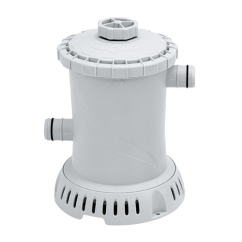
Other manuals for SUMMER WAVES ST1100

3

This manual suits for next models

1

Other Polygroup Swimming Pool Pump manuals

Polygroup SUMMER WAVES RX600 User manual

Polygroup

Polygroup SUMMER WAVES RX600 User manual

Polygroup SUMMER WAVES RP350 User manual

Polygroup

Polygroup SUMMER WAVES RP350 User manual

Polygroup SUMMER WAVES SKIMMERPLUS SFS400 User manual

Polygroup

Polygroup SUMMER WAVES SKIMMERPLUS SFS400 User manual

Polygroup SUMMER WAVES SKIMMERPLUS SFX330 User manual

Polygroup

Polygroup SUMMER WAVES SKIMMERPLUS SFX330 User manual

Polygroup SUMMER WAVES ST1100 User manual

Polygroup

Polygroup SUMMER WAVES ST1100 User manual

Polygroup SFX600 User manual

Polygroup

Polygroup SFX600 User manual

Polygroup SUMMER WAVES Series User manual

Polygroup

Polygroup SUMMER WAVES Series User manual

Polygroup SUMMER WAVES RP400 User manual

Polygroup

Polygroup SUMMER WAVES RP400 User manual

Popular Swimming Pool Pump manuals by other brands

Davey StarFlo DSF150CE Installation and operating instructions

Davey

Davey StarFlo DSF150CE Installation and operating instructions

Pentair STA-RITE SWIMMEY Series instruction manual

Pentair

Pentair STA-RITE SWIMMEY Series instruction manual

Polaris PB4-60 installation instructions

Polaris

Polaris PB4-60 installation instructions

Perle MP2-POOL-T Programming instructions

Perle

Perle MP2-POOL-T Programming instructions

Pentair Pool Products Pump Waterfall Operation and service manual

Pentair Pool Products

Pentair Pool Products Pump Waterfall Operation and service manual

Harmopool QBIC instruction manual

Harmopool

Harmopool QBIC instruction manual

CARVIN MAXI Series Operation & installation instructions

CARVIN

CARVIN MAXI Series Operation & installation instructions

Badu Tec BADU Resort Installation and operation manual

Badu Tec

Badu Tec BADU Resort Installation and operation manual

Intex Krystal Clear 638G owner's manual

Intex

Intex Krystal Clear 638G owner's manual

Pentair OPTIFLO 348195SR Installation and user guide

Pentair

Pentair OPTIFLO 348195SR Installation and user guide

Wayne WAPC250 Operating instructions & parts manual

Wayne

Wayne WAPC250 Operating instructions & parts manual

Hayward Pool SP2600X5 Installation and operating instructions

Hayward Pool

Hayward Pool SP2600X5 Installation and operating instructions

IML AMERICA SA Series Installation and maintenance manual

IML

IML AMERICA SA Series Installation and maintenance manual

Intex CS15220 owner's manual

Intex

Intex CS15220 owner's manual

atecpool ATECF11 Installation Guide and User Manaul

atecpool

atecpool ATECF11 Installation Guide and User Manaul

Hidrotermal HIDRO-HMT300 user manual

Hidrotermal

Hidrotermal HIDRO-HMT300 user manual

HY-CLOR 2 speed pool pump Installation and operation manual

HY-CLOR

HY-CLOR 2 speed pool pump Installation and operation manual

Astral Pool VICTORIA DUAL SPEED manual

Astral Pool

Astral Pool VICTORIA DUAL SPEED manual

manuals.online logo
manuals.online logoBrands
  • About & Mission
  • Contact us
  • Privacy Policy
  • Terms and Conditions

Copyright 2025 Manuals.Online. All Rights Reserved.