AquaMetrix SHARK TX User manual

SHA K
TX
& SHA K
TXP
MULTI-PA AMETE
T ANSMITTE USE ’S MANUAL
AquaMetrix Inc.
1245 Maple ill Ct., Unit 7
Newmarket, ON
Canada, L3Y 9E8
Tel: (800) 742-1413
(905) 954-0841
Fax: (905) 954-0415
www.aquametrix.com
N116-35 Rev 3 A57-24

Subject Page No.
Introduction 1
Section 1 - Specifications 2
Section 2 - Installation 3 - 5
Section 3 - Electrical Connections & Setup 6 - 11
Differential Probe connection & setup 7
Combination Probe connection & setup 8
Conductivity Cell (Contacting style) connection & setup 9
Paddle Wheel Flow Sensor connection & setup 10
4-20mA Isolated Output 11
Section 4 - Using the Transmitter in pH Mode 12
LCD Menu 13 - 28
Section 5 - Using the Transmitter in ORP Mode 29
LCD Menu 30 - 44
Section 6 - Using the Transmitter in Conductivity Mode 45
LCD Menu 46 - 62
Section 7 - Using the Transmitter in Flow Mode 63
LCD Menu 64 - 78
Appendix A - Probe Configuration Table 79
Return Policy & Warranty Plan 80
MULTI-PARAMETER TRANSMITTER USER’S MANUAL
Table of Contents

MULTI-PARAMETER TRANSMITTER USER’S MANUAL
Introduction
Introduction Page 1
The SHARKTX & SHARKTXP multi-parameter transmitter is a microprocessor based
transmitter capable of measuring one of the following parameters, pH, ORP, conductivi-
ty or flow.
When shipped from the factory, the Shark is not set to measure any one parameter.
When the Shark is powered up for the first time, it will display the meter selection
screen where the meter type must be selected. (refer to section 4.5 Meter Selection)
This meter selection screen will only be displayed when the Shark is powered up for the
first time.
After the user selects a meter type the Shark will remain set to that meter type until it is
changed with the meter selection menu function in the Utilities menu.
To return the Shark to its factory settings, the user must re-select the current meter type
from the meter selection menu function. This will override all set-points and return all
settings back to the factory settings.
The Shark Users menu has been divided into five main categories
- Calibration, used to calibrate the Shark with the selected sensor
- Utilities, used to manually control or override the outputs.
- Setup, used to configure the Sharks many options
- Diagnostics, used to troubleshoot problems with the Shark or sensor
- Outputs, used to configure the Shark’s 4 to 20mA output.
SHARKTX is packaged in a rugged NEMA 4X polycarbonate enclosure with a universal
mounting kit for surface, panel and pipe-mount applications. This enclosure is perfect for
stand-alone or panel-mount operation.
SHARKTXP enclosure is also polycarbonate with a NEMA 4X front panel. Panel mount,
and DIN rail mounting hardware are supplied.

MΩ/cm30 to 19.99 0.01
uS/cm3
0 to 2.000 0.01
0 to 20.00 0.1
0 to 200.0 0.1
0 to 5000 1.0
mS/cm30 to 20.00 10
0 to 200.0 50
Section I - Specifications Page 2
MULTI-PARAMETER TRANSMITTER USER’S MANUAL
Section I - Specifications
pH ORP Conductivity Flow
Display 2 x 16 alpha-numeric LCD display
Power Requirements 4 to 20mA, Loop Powered, 16 to 32 VDC
Flow: 0 to 9999 with
selectable
flow rate units
pH: 0.01 to 14.00 ORP: -1999 to +1999mV
Volume: 0 - 999 with Auto Range
Measuring Range (Dependent on sensor)
Flow rate units: Gallons (GP), Cubic
Temp: 0 to 100°C or Temp: 0 to 100°C or
Feet (CF), Liters (LP), Cubic Meters
32° to +212°F 32° to +212°F (
CM), custom by entering factor
related to Gallons
Time units: Seconds (S), Minutes (M)
Temp: 0 to 100°C or 32° to +212°F
Hours (H)
Automatic or Manual
Temperature Automatic or Manual Not required User selectable temperature Not required
Compensation 0 - 100°C (32° to +212°F)
compensation slope 0.0 to 10.0%/°C.
0 to 100°C (32° to +212°F)
Temperature Unit °C or °F Not required
Temperature Sensor User selectable: 300ΩNTC Thermistor, 3000ΩNTC Thermistor or Pt. 1000 RTD Not required
Auto-Calibration Manual Calibration Dry Calibration
Calibration Modes Manual Calibration Temperature Calibration Sample Calibration K factor Input
Temperature Calibration Temperature Calibration
Ambient Conditions Temperature: -20°C to +60°C or -4°F to +140°F Humidity: 0 to 90% RH (non-condensing)
Sensor to Transmitter Differential Sensor: 3000 ft 300 ft 2000 ft
Distance Combination Sensor: 10 ft
Analog Output 4 to 20mA
Isolated Output, Range expand 0 to 100% of full scale (min segment 10% of full scale), max. load 800Ω
Memory Back-up All user settings are retained indefinitely in memory (EEPROM)
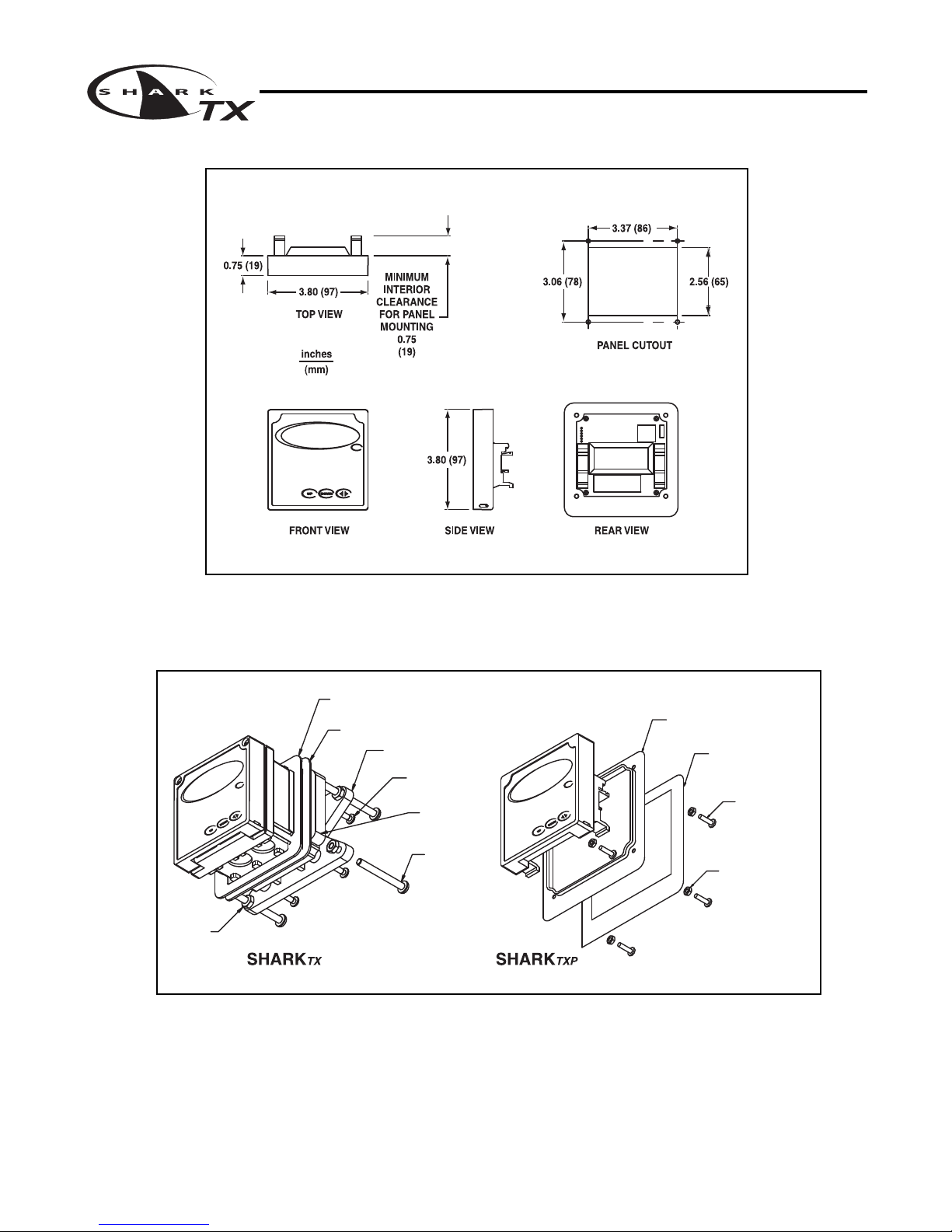
SHARKTX Enclosure: NEMA 4X, 1/4 DIN, polycarbonate enclosure with two 1/2”conduit holes
Mechanical SHARKTXP Enclosure: NEMA 4X front panel, 1/4 DIN, polycarbonate
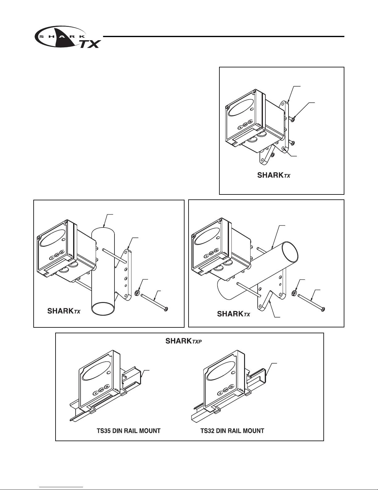
SHARKTX Mounting: Universal Mounting kit for surface, pipe and panel mount included
SHARKTXP Mounting: Panel and DIN rail mount included
Sensor Input Probe: -600 to +600mV Probe: -1999 to +1999mV Cell: 0 to 9999ΩPaddle: 0 to 2000Hz
Temp. Sensor: 0 to 9999ΩTemp. Sensor: 0 to 9999ΩTemp. Sensor: 0 to 9999Ω
Invalid Entries Invalid entries cannot be stored
Manual Test Mode Process value can be simulated with arrow keys to verify correct setup of output
Output Hold 4 to 20mA output is placed on hold when the transmitter is in Menu mode
Recall data from last
Recall data from last calibration, calibration mode, calibration, calibration buffer
Calibration Data 1st & 2nd accepted buffer value and probe mV output, accepted value, and cell Recall store K factor.
calibration temperature, calibration slope, and probe resistance, calibration
efficiency temperature
Auto Return User selectable auto return if the transmitter is left in menu mode for more than 10 min.
Display Damping User can select rate at which the transmitter updates display. Enables display damping of unstable process
Net Weight SHARKTX: 0.71 lbs (0.32 kg)
SHARKTXP: 0.25 lbs (0.12 kg)
Approvals ULC (pending)

MULTI-PARAMETER TRANSMITTER USER’S MANUAL
Section 2 - Installation
Section 2 - Installation Page 3
2.1 Unpacking
Save the shipping carton and packing material in case the instrument needs to be stored or
returned. Inspect the instrument and packing material for shipping damage and report any
problems immediately.
2.2 Location
Locate the transmitter close to the sensor. The list below gives typical maximum distances for
various sensors. Refer to the sensor specifications for exact information.
• Aquametrix Differential PH Probe 3000 ft (914 meters)
• Aquametrix Combination PH Probe 10 ft (3 meters)
• Aquametrix Conductivity Probe 300 ft (91 meters)
• Aquametrix Flow sensor 2000 ft (610 meters)
2.3 Mounting
Fig 2.1 SHARKTX Transmitter dimensions
Dwg# N106-128

Section 2 - Installation Page 4
MULTI-PARAMETER TRANSMITTER USER’S MANUAL
Section 2 - Installation
Panel Mount – The transmitters can be panel mounted to a panel using the hardware kit
provided. The panel cutout dimensions are shown in fig. 2.1 and 2.2.
EXTERNAL
PANEL GASKET
QTY.1
SCREW
4-40 X 3/4"
QTY.4
NUT
4-40
QTY.4
PANEL
(CUSTOMER SUPPLIED)
PANEL
(CUSTOMER SUPPLIED)
EXTERNAL PANEL
GASKET QTY.1
SCREW
1/4-20 X 2-1/2"
QTY.4
NUT
1/4-20
QTY.4
UNIVERSAL
MOUNTING
CLAMP QTY.2
SCREW
10-24 X 1/2"
QTY.4
UNIVERSAL MOUNTING
BRACKET
QTY.1
Figure 2.3 Panel Mount
Fig 2.2 SHARKTXP Transmitter dimensions
Dwg# N106-129
Dwg# N105-101 & N105-104

MULTI-PARAMETER TRANSMITTER USER’S MANUAL
Section 2 - Installation
Section 2 - Installation Page 5
MIN. PIPE DIA.
1" PIPE (NOMINAL)
MAX. PIPE DIA.
2" PIPE (NOMINAL)
NUT
10-24
QTY.4 SCREW
10-24 X 3-1/2"
QTY.4
UNIVERSAL MOUNTING
BRACKET
QTY.1
Figure 2.6 Horizontal Pipe Mount
Surface Mount – The SHARKTX can be surface
mounted using the hardware kit provided with the unit.
Pipe Mount – The SHARKTX can be mounted to a
horizontal or vertical pipe with:
• a minimum outside diameter of 1.30” (33mm) (for
example 1” CPVC pipe)
• and a maximum of 2.375” (60mm) (for example 2”
CPVC pipe)
DIN Rail Mount – The SHARKTXP can be DIN rail
mounted or panel mounted. See figure 2.3 & figure 2.7.
MIN. PIPE DIA.
1" PIPE (NOMINAL)
MAX. PIPE DIA.
2" PIPE (NOMINAL)
SCREW
10-24 X 3-1/2"
QTY.4
NUT
10-24
QTY.4
UNIVERSAL MOUNTING
BRACKET
QTY.1
Fig. 2.5 Vertical Pipe Mount
UNIVERSAL MOUNTING
BRACKET
QTY.1
SCREW
10-24 X 1/2"
QTY.4
HOLES Ø1/4"
FOR MOUNTING SCREWS
QTY.4
(CUSTOMER SUPPLIED)
Figure 2.4 Surface Mount
TS35 DIN RAIL MOUNT
(CUSTOMER SUPPLIED)
TS32 DIN RAIL MOUNT
(CUSTOMER SUPPLIED)
Figure 2.7 DIN Rail Mount
Dwg# N105-101 Dwg# N105-101
Dwg# N105-101
Dwg# N105-104

3.1 Conduit Connections
The S ARK
TX
has two 1/2” conduit holes at the bottom of the enclosure as shown on fig. 2.1. The
unit is shipped with these holes plugged with liquid tight conduit seals. These must be left in unused
holes to maintain the NEMA 4X integrity. Use approved conduit hubs to connect the conduit, connect
these to the conduit before connecting to the enclosure.
3.2 Power Connections
Section 3 - Electrical Connections and Setup Page 6
MULTI-PA AMETE T ANSMITTE USE ’S MANUAL
Section 3 - Electrical Connections and Setup
Figure 3.1 Connections
Dwg# N104-41

MULTI-PA AMETE T ANSMITTE USE ’S MANUAL
Section 3 - Electrical Connections and Setup
Section 3 - Electrical Connections and Setup Page 7
3.3 p and ORP Differential Probe connections and setup
The drawing shows the connections for the Aquametrix Differential (5 wire) probe. The cable
should be run in a conduit separate from AC power wires, and via a separate conduit hole.
Figure 3.2 Connections for Differential (5 wire) p or ORP probe
Once connected, step through the LCD menus to
select the probe in the order shown. The first two
steps may be skipped if the meter is already con-
figured for p or ORP and a Differential Probe.
When using a p probe, it is important to ensure
that the transmitter is reading the probe tempera-
ture correctly for accurate temperature compensa-
tion. The ORP probe does not require temperature
compensation, although the transmitter can dis-
play process temperature measured by the probe.
The factory temperature calibration is usually
accurate enough that no adjustments are neces-
sary.
Dwg# N104-42
CAUTION:
Always disconnect
the loop power
before wiring or
unwiring a sensor

Section 3 - Electrical Connections and Setup Page 8
MULTI-PARAMETER TRANSMITTER USER’S MANUAL
Secti n 3 - Electrical C nnecti ns and Setup
3.4 pH or ORP Com ination Pro e connections and setup
The drawing shows the connections for the Aquametrix Com ination pro e. The ca le should e run
in a conduit separate from AC power wires, and via a separate conduit hole. The ca le length should
not exceed 10 feet (3 meters).
Fig. 3.3 Connections for the 2 and 4 wire Com ination Pro e
Once connected, step through the LCD menus to select the pro e in the order shown. The first two steps
may e skipped if the meter is already configured for a Com ination Pro e. If a two wire pH pro e is
used, which has no temperature sensor, ensure that the Temp. Comp. Override is set to same temper-
ature as the uffer efore cali rating. If a two wire ORP pro e is used, you can lank the Temp display
with the T DISP OVERRIDE menu.
The 2 wire version has
no temperature sensor
and is connected via a
coaxial wire.
In a pH meter, the user
should set the T COMP
OVERRIDE menu to ON
(Section 4.10) and adjust
the temperature setting to
the actual pro e temper-
ature.
In an ORP meter, the
user should set the
T.DISP OVERRIDE to
ON (Section 5.9) to lank
the temperature reading
on the display.
The 4 wire version has
two additional wires for
the pro e internal tem-
perature sensor. Ensure
that the T COMP OVER-
RIDE r T.DISP OVER-
RIDE is OFF.
Dwg# N104-43
CAUTION:
Always disconnect
the loop power
efore wiring or
unwiring a sensor

MULTI-PA AMETE T ANSMITTE USE ’S MANUAL
Section 3 - Electrical Connections and Setup
Section 3 - Electrical Connections and Setup Page 9
3.5 Conductivity Cell (Contacting style) connections and setup
Figure 3.4 Connections for Conductivity Cells
Once connnected, step
through the LCD menus to
select the cell in the order
shown. The TEMP COMP
CURVE setup default is
1.8%/deg C. This is accept-
able for most process appli-
cations. If your process is
significantly different from
this, change the setting in
the TEMP COMP CURVE
menu.
The drawing shows the connections for the Aquametrix Conductivity Cells (Contacting style). The cable
should be run in a conduit seperate from the AC power wires, and via a seperate conduit hole. The cell
cable length should not exceed 300ft. (91 meters).
Dwg# N104-44
CAUTION:
Always disconnect
the loop power
before wiring or
unwiring a sensor

Section 3 - Electrical Connections and Setup Page 10
MULTI-PA AMETE T ANSMITTE USE ’S MANUAL
Section 3 - Electrical Connections and Setup
3.6 Paddle Wheel Flow Sensor connections and setup
Figure 3.5 Connections for Flow Sensor
Once connected, step through
the LCD menus to select the
sensor in the order shown. The
Sensor K factor (pulses per U.S.
Gallon) is usually printed on the
side of the sensor or on a label
attached to the sensor cable.
The drawing shows the connnections for a typical paddle wheel flow sensor. The cable to the
sensor should not exceed 2000’ (600 meters).
Dwg# N104-45
CAUTION:
Always disconnect
the loop power
before wiring or
unwiring a sensor

Section 3 - Electrical Connections and Setup Page 11
MULTI-PARAMETER TRANSMITTER USER’S MANUAL
Section 3 - Electrical Connections and Setup
3.10 MANUAL TEST MODE
(LCD MENU SECTIONS - pH: 4.4, ORP: 5.3, Conductivity: 6.4, Flow: 7.2)
The setup can be tested using Manual Test Mode to simulate process changes.
MANUAL TEST MODE is used to simulate a process reading in order to verify the correct
response of the output.
3.11 4-20 mA Isolated Output
(LCD MENU SECTIONS - pH: 4.15, ORP: 5.14, Conductivity: 6.16, Flow: 7.14)
The Transmitter has a single 4 to 20mA output, electrically isolated from the ground. The output
can source current into a resistive load. Maximum resistance depends on supply voltage.
Drawing on page 6 (Fig. 3.1)
The output is dedicated to track the process and has fully independent and fully adjustable 4 &
20 mA output setpoints. This will enable the operator to span the output over the desired range.
The output can be precisely trimmed through the LCD menu for precision applications.
The drawing on page 6 (Fig. 3.1) shows the connections for the output.
Wire Specification: 22 AWG 7/30, insulation 0.010”

MULTI-PARAMETER TRANSMITTER USER’S MANUAL
Section 4 - Using the Transmitter in pH Mode
Section 4 - Using the Transmitter in pH Mode Page 12
SIMPLE THREE-BUTTON INTERFACE
FOR FAST & EASY SETUP
(REFER TO SECTIONS 4.0 TO 4.15)
2 LINE, 16 CHARACTER
LCD DISPLAY
MAIN MENU INTERFACE
SCREEN
1/4" TURN SCREWS
(FOR SHARKTX ONLY)
UNIT LABEL
LABEL TO INDICATE UNIT OF
MEASURE SHARK IS
CONFIGURED FOR.

MULTI-PARAMETER TRANSMITTER USER’S MANUAL
pH - Menu Overview 4.0
pH - Menu Overview 4.0 Page 13
DOWN
DOWN
DOWN
DOWN
DOWN
DOWN
DOWN
DOWN
DOWN
DOWN
DOWN
DOWNDOWN
DOWNDOWN
DOWN
DOWN
DOWNDOWN
DOWN
DOWN
DOWN
DOWN
DOWN
DOWN
DOWN
DOWNDOWN
SELECT DEG C OR DEG F
ENABLE TIME OUT
PROBE WITHOUT TEMP. SENSOR
TEMPERATURE SETUP FOR
SETUP DISPLAY AND
OUTPUT RESPONSE TIME
SELECT TYPE OF
FROM MENU
DISPLAY
FIRMWAVE REVISION
SEC. 4.12
DISPLAY PREVIOUS
CALIBRATION DATA
SEC 4.13
DISPLAY UNCALIBRATED
PROBE DATA
SEC 4.14
SEC. 4.9
SEC 4.10
SEC 4.11
SEC. 4.6
SEC 4.7
SELECT TYPE OF
TEMP SENSOR
SEC 4.8
pH PROBE
RUN MODE
SEC. 4.3
UP
NOTE
PRESS THE AND KEYS
TOGETHER TO GO IMMEDIATELY BACK TO
RUN MODE
DOWN
SELECT TYPE
OF METER
SEC. 4.5
VERIFY OUTPUTS
SIMULATE PROCESS
SEC. 4.4
AUTO CALIBRATE
MANUAL CALIBRATE
SENSOR IN pH PROBE
CALIBRATE TEMP.
pH PROBE
SEC. 4.1
pH PROBE
SEC. 4.2
DIAGNOSTICS
EXIT
SENSOR INPUT
CALIBRATION DATA
FIRMWARE REV
EXIT
DISPLAY DAMPING
T.COMP OVERRIDE
EXIT
AUTO RETURN
TEMP UNIT
TEMP SENSOR
PROBE SELECT
7.15pH 25.0C
UTILITIES
SETUP
CALIBRATION
MANUAL TEST MODE
METER SELECTION
EXIT
EXIT
TEMP CALIBRATION
MANUAL CAL pH
AUTO CAL pH
DOWN
DOWN
DOWN
4-20 mA OUTPUT
SETUP
SEC 4.15
EXIT
4-20mA
OUTPUT

pH - Calibration Menu - Manual Calibrate 4.1 Page 14
MULTI-PARAMETER TRANSMITTER USER’S MANUAL
pH - Calibration Menu - Manual Calibrate 4.1
DOWN
DOWN
DOWN
UP DOWN
DOWN
DOWN
UP DOWN
DOWN
DOWN
DOWN
DOWN
DOWN
DOWN
UP DOWN
DOWN
UP DOWN
DOWN
Please wait for the controller to complete
the measurement
After 5 seconds, the controller will
compute the slope of the calibration, the
estimated probe efficiency and the probe
temperature.
Then press to store the value and
complete the Manual Calibration
Then press to store the value and move
to BUFFER2
Use the and keys to adjust
the reading until it agrees with the actual
buffer pH value
When complete, the controller will report
the measured value
The controller will read the pH value,
averaging a number of results to get a
stable calibration value.
Place the probe in the second buffer.
Be sure to clean and rinse the Probe first with
D.I. water and then insert it in the 4.00 buffer.
Press
Use the and keys to adjust
the reading until it agrees with the actual
buffer pH value
When complete, the controller will report
the measured value
Please wait for the controller to complete
the measurement
The controller will read the pH value,
averaging a number of results to get a
stable calibration value.
Place the probe in the first buffer solution, be
sure to clean and rinse the Probe first with D.I.
water and then insert it in the 7.00 buffer.
Press
If the calibration is OK, use the key
to move the cursor over the Y text and
press the down key.
If the calibration did not appear to be
correct, press the key
which will return back to the Manual
Cal menu.
RUN MODE
UP
NOTE
PRESS THE AND KEYS
TOGETHER TO GO IMMEDIATELY BACK TO
RUN MODE
DOWN
Press to store the calibration
data and return back to the Manual
Cal menu so the user can select
another function.
Then press to move the
cursor to the RH position
Then press to move the
cursor to the RH position
STORE? Y N STORE? Y N
IF BUFFER1 READYCALIBRATION MANUAL CAL pH
MANUAL CAL pH
MANUAL CAL pH
BUFFER2 4.00 >
SLOPE 61.22MV/pH
EFF 95% 24.8C
BUFFER1 7.00 >
MANUAL CAL pH
BUFFER2 4.4 0 >
MANUAL CAL pH
BUFFER2 4.0 0 >
BUFFER2 WAIT...
RUNNING MANU CAL
IF BUFFER2 READY
PRESS 'DOWN'
MANUAL CAL pH
MANUAL CAL pH
BUFFER1 7.0 0 >
RUNNING MANU CAL
BUFFER1 WAIT...
PRESS 'DOWN'
BUFFER1 7.3 5 >
MANUAL CAL pH
7.15pH 25.0C
MANUAL CAL pH
This example shows a MANUAL
calibration with buffers of 7pH & 4pH.
When performing a manual
calibration, any two known buffer
solutions can be used.

MULTI-PARAMETER TRANSMITTER USER’S MANUAL
pH - Calibration Menu - Auto Calibrate 4.2
pH - Calibration Menu - Auto Calibrate 4.2 Page 15
DOWN
DOWN DOWN
DOWN
DOWN
DOWN
DOWN
DOWN
DOWN DOWN
DOWN
DOWN
If an erros occurs, the controller will indicate a
"BUFFER ERROR" alarm. This could be caused by
-using a defective buffer
-incorrect probe wiring
- defective probe
Press to return to the Auto cal menu, try to
correct the problem and calibrate again, or go to the
diagnotics menus to test the probe
see Section 4.16
If an erros occurs, the controller will indicate a
"BUFFER ERROR" alarm. This could be caused by
-using the same buffer twice
- using a defective buffer
-incorrect probe wiring
- defective probe
Press to return to the Auto cal menu, try to
correct the problem and calibrate again, or go to the
diagnotics menus to test the probe
If the calibration did not appear to
be correct, press the key
which will return back to the Auto cal
menu.
UP
NOTE
PRESS THE AND KEYS
TOGETHER TO GO IMMEDIATELY BACK TO
RUN MODE
DOWN
This will store the calibration
data and return back to the
Auto cal setup so the user
can select another function.
If the calibration is OK, use the key to
move the cursor over the Y text and press the
down key.
After 5 seconds, the controller will
compute the slope of the calibration, the
estimated probe efficiency and the probe
temperature.
When complete, the controller will report the
measured value
When complete, the controller will report
the measured value
Press the key to move to Buffer 2
Please wait for the controller to complete
the measurement
The controller will read the pH value,
averaging a number of results to get a
stable calibration value.
Place the probe in the second buffer
solution.Be sure to clean and rinse the
Probe first with D.I. water and then insert
it in the 4.00 buffer.
Press the key
Please wait for the controller to complete
the measurement
The controller will read the pH value,
averaging a number of results to get a
stable calibration value.
Place the probe in the first buffer solution,
be sure to clean and rinse the Probe first
with D.I. water and then insert it in the 7.00
buffer.
Press
RUN MODE
AUTO CAL pH
STORE? Y N STORE? Y N
AUTO CAL pH
AUTO CAL pH
EFF 95% 24.8C
SLOPE 61.22MV/pH
BUFFER2 4.00 >
AUTO CAL pH
AUTO CAL pH
BUFFER ERROR
CONTINUE >
RUNNING AUTO CAL
BUFFER2 WAIT...
BUFFER1 7.00 >
PRESS 'DOWN'
IF BUFFER2 READY
BUFFER ERROR
CONTINUE >
PRESS 'DOWN'
IF BUFFER1 READY
RUNNING AUTO CAL
BUFFER1 WAIT...
CALIBRATION
7.15pH 25.0C
MANUAL CAL pH
This example shows an AUTO
calibration with buffers of 7pH & 4pH.
When performing an auto calibration,
any two standard buffers of 4.00, 7.00
or 10.00 pH can be used. The buffers
will be automatically recognized if the
probe measures them within +/- 1 pH
of their nominal value.

pH - Calibration Menu - Temperature Calibration 4.3 Page 16
MULTI-PARAMETER TRANSMITTER USER’S MANUAL
pH - Calibration Menu - Temperature Calibration 4.3
DOWN
DOWN DOWN
DOWNUP
DOWN
DOWN
DOWN
UP
DOWN
DOWN
DOWN
DOWN
DOWN
If the Temperature Compensation Override is set to ON
(see section 4.11), the Shark cannot calibrate the
temperature sensor. This display will appear to alert the
user to the condition.
If the calibration does not appear to
be correct, press the key
which will return back to the Temp
Calibration menu.
UP
NOTE
PRESS THE AND KEYS
TOGETHER TO GO IMMEDIATELY BACK TO
RUN MODE
DOWN
This will store the calibration data
and return back to the Temp
Calibration setup so the user can
select another function.
Use the and to adjust
the reading until it agrees with the
known temperature of the probe
Press the key to accept the
reading and move to the store function
"T FACTOR SHIFTED" will be
displayed for 5 seconds to indicate that
the temperature sensor has been
calibrated.
The Shark will then move to the store
function.
The controller displays the current probe
temperature.
If this incorrect, the controller can be
adjusted to compensate.
Press the key once
which will move the cursor
back to the RH side of
temperature display.
Press the key once which will move
the cursor over the least sign. digit of the
temperature display.
RUN MODE
AUTO CAL pH
STORE? Y N
TEMP CALIBRATION
STORE? Y N
TEMP CALIBRATION
TEMP CALIBRATION
25.0C >
T FACTOR SHIFTED
25. 0 C >
TEMP CALIBRATION
TEMP CALIBRATION
TEMP CALIBRATION
TEMP CALIBRATION
22. 4 C >
22.4C >
TEMP CALIBRATION
TEMP O/R ON >
7.15pH 25.0C
CALIBRATION MANUAL CAL pH

MULTI-PARAMETER TRANSMITTER USER’S MANUAL
pH - Utilities Menu - Manual Test Mode 4.4
pH - Utilities Menu - Manual Test Mode 4.4 Page 17
DOWN
DOWN
DOWN
UP DOWN
DOWN
UP DOWN
Manual Test Mode is used to simulate a process reading
in order to verify the correct response of the output.
When in the Manual Test Mode, the output IS no longer
placed on hold as it is when in the rest of the menu.
NOTE:
When the user exits the Manual Test Mode, the 4-20mA
output will remain in the Test Mode state until the operator
enters the run mode. The output will then revert back to
the previous On-line state.
The 4-20 mA output will track
the change in process value
RUN MODE
UP
NOTE
PRESS THE AND KEYS
TOGETHER TO GO IMMEDIATELY BACK TO
RUN MODE
DOWN
Press the key once to
move the cursor to the RH side
of the display
The 4 to 20 mA output will follow the process
value change.
Press the key to return to the
MANUAL TEST MODE menu
Use the and keys to change
the simulated process value.
Press the key once which will
move the cursor over the least digit of the
simulated process value.
TEST 7.0 0 >
TEST 7.00 >
7.15pH 25.0C
CALIBRATION
UTILITIES
19.0mA
19.0mA
TEST 13.1 5 >
TEST 13.15 >
MANUAL TEST MODE
12.0mA
12.0mA
19.0mA
TEST 13.1 5 >
DOWN

pH - Utilities Menu - Meter Selection 4.5 Page 18
MULTI-PARAMETER TRANSMITTER USER’S MANUAL
pH - Utilities Menu - Meter Selection 4.5
DOWNDOWN
DOWN
DOWN
DOWN
DOWN
DOWN
DOWN
DOWN
DOWN
DOWN
DOWN
DOWN DOWN
DOWN
If you do not wish to initialize to this
type of meter after all, then press
key to return back to the Meter
Selection menu
Then press
The controller will initialize itself for a
specific meter
If you do wish to initialize to this
type of meter, press the
key to highlight the Y character
UP
NOTE
PRESS THE AND KEYS
TOGETHER TO GO IMMEDIATELY BACK TO
RUN MODE
DOWN
Press the key to Exit and
return to the Utilities menu
RUN MODE
Press the key to initialize the
controller as a Flow meter
Press the key to initialize the
controller as a Conductivity meter
The Meter Selection menu is used to select the meter type that the
controller is configured for, either pH, ORP, Conductivity or FLow.
Once selected, the controller will initialize itself for the selected meter's
functionality and move to run mode.
Press the key to initialize the
controller as an ORP meter
Press the key to initialize the
controller as a pH meter.
INITIALIZE? Y N
INITIALIZE? Y N
INITIALIZE? Y N
INITIALIZE? Y N
INITIALIZE? Y N
PH
PH
E XIT
MANUAL TEST MODE
7.15pH 25.0C
UTILITIES
CALIBRATION
METER SELECTION
C ONDUCTIVITY
FLOW
EXIT
F LOW
CONDUCTIVITY
O RP
CONDUCTIVITY
FLOW
ORP
P H
ORP
PH
To reset the controller back to all
the factory default values, reselect
the current meter type
This manual suits for next models
1
Table of contents