Aquametro Oil & Marine CONTOIL VZF II Service manual

Mounting and operating instructions
CONTOIL®
VZF II / VZFA II, DN 15 –50
Table of Contents
1Safety.............................................................................................................................2
1.1 Intended Use ............................................................................................................................................................ 2
1.2 Notes on safety rules and symbols.................................................................................................................. 2
1.3 Safety rules and precautions .............................................................................................................................. 3
1.4About the operating manual.............................................................................................................................. 3
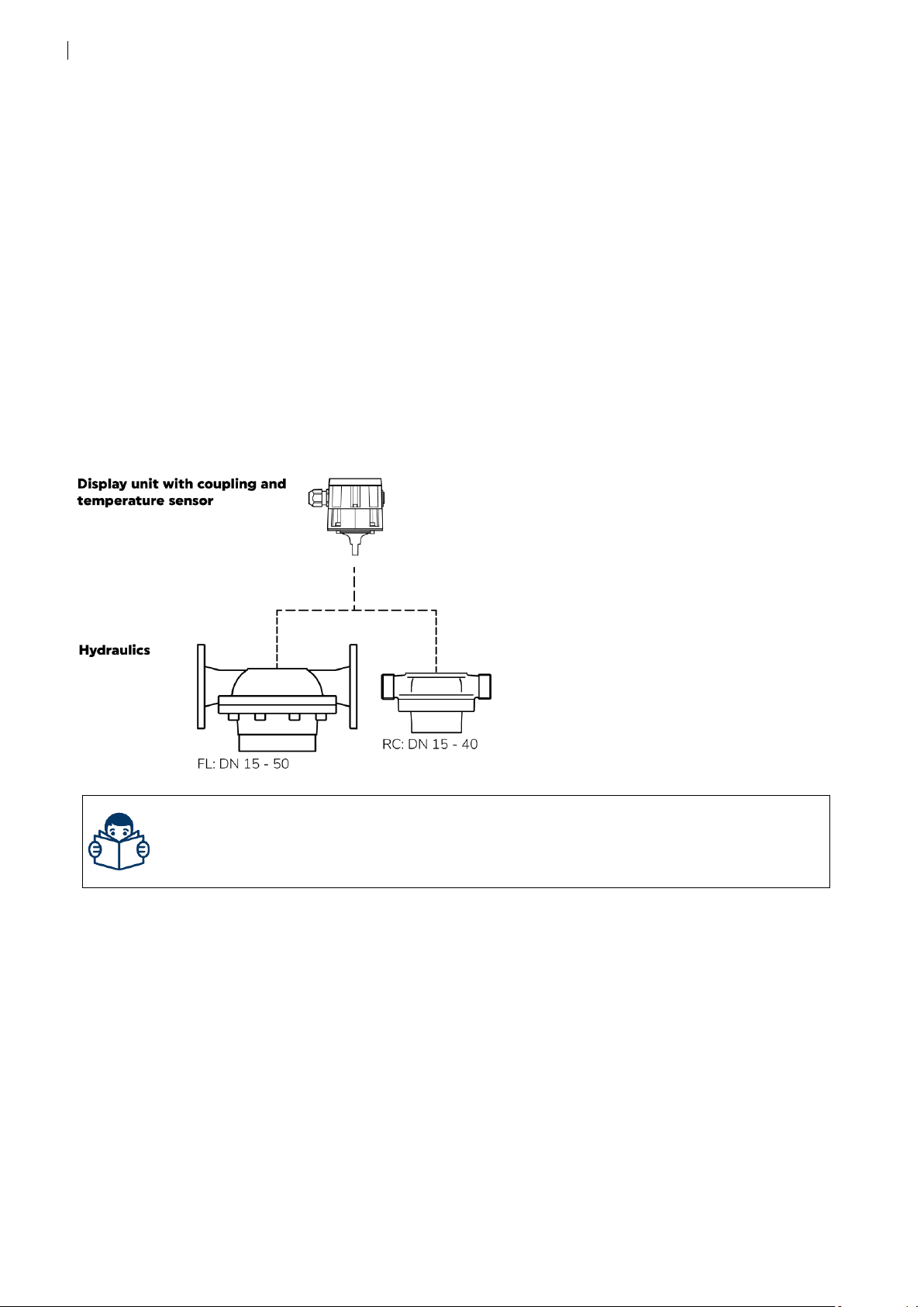
2Product description .....................................................................................................4
2.1 Flow meter configuration .................................................................................................................................... 4
3Scope of delivery an accessories................................................................................5
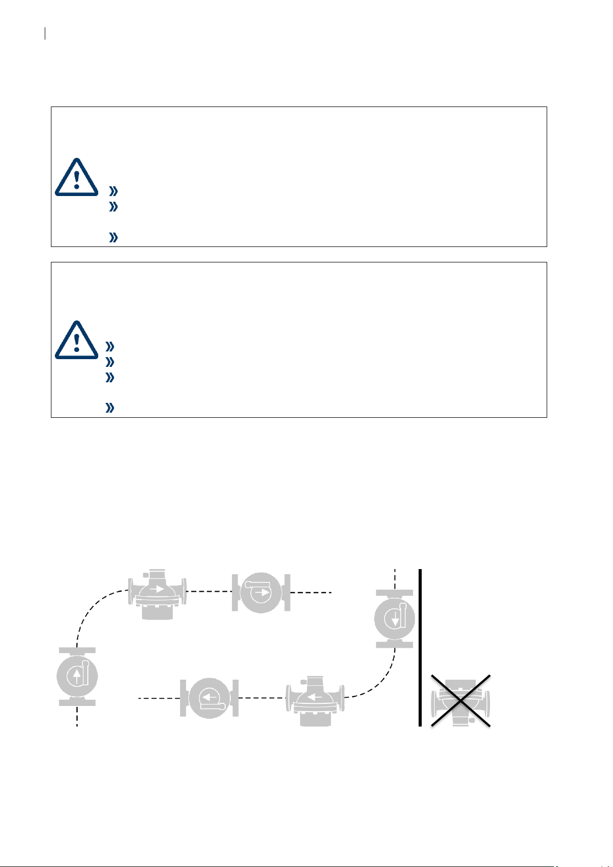
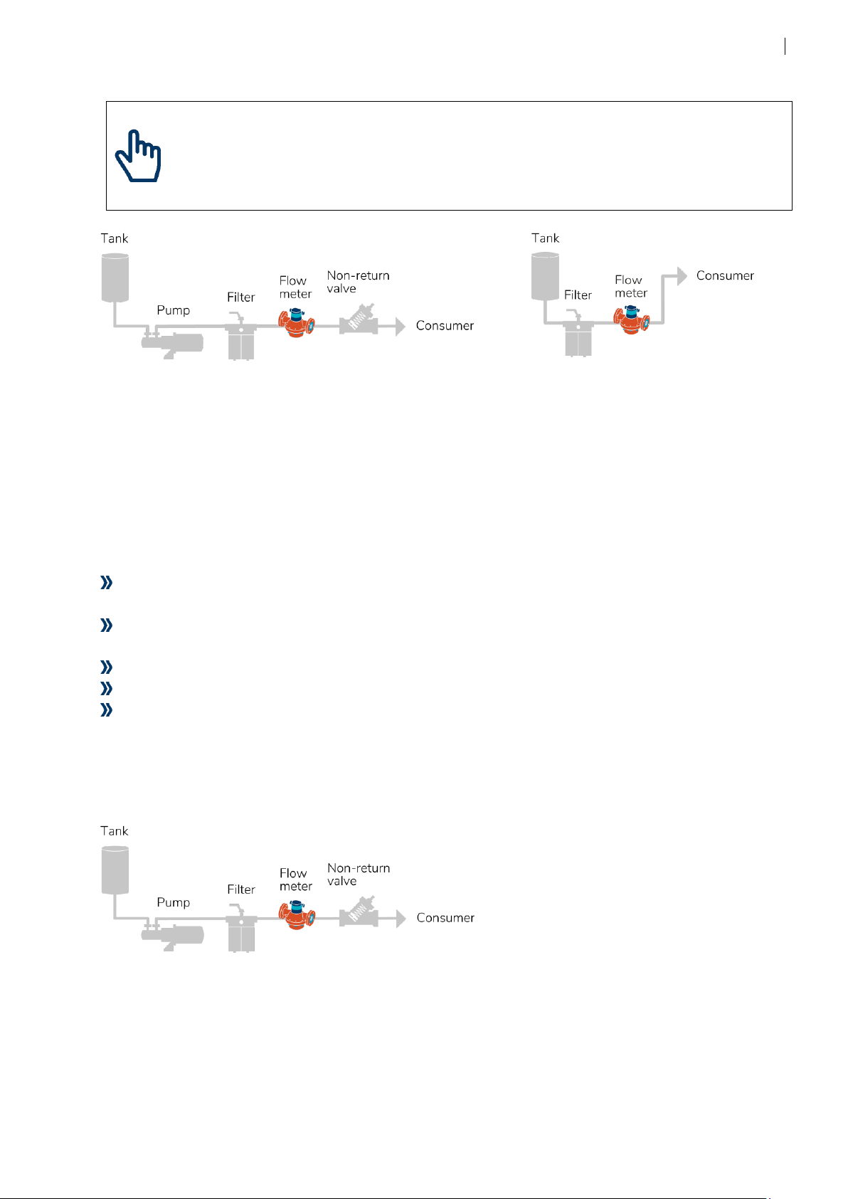
4Mounting ......................................................................................................................6
4.1 Mechanical installation.......................................................................................................................................12
4.2 Electrical Installation............................................................................................................................................14
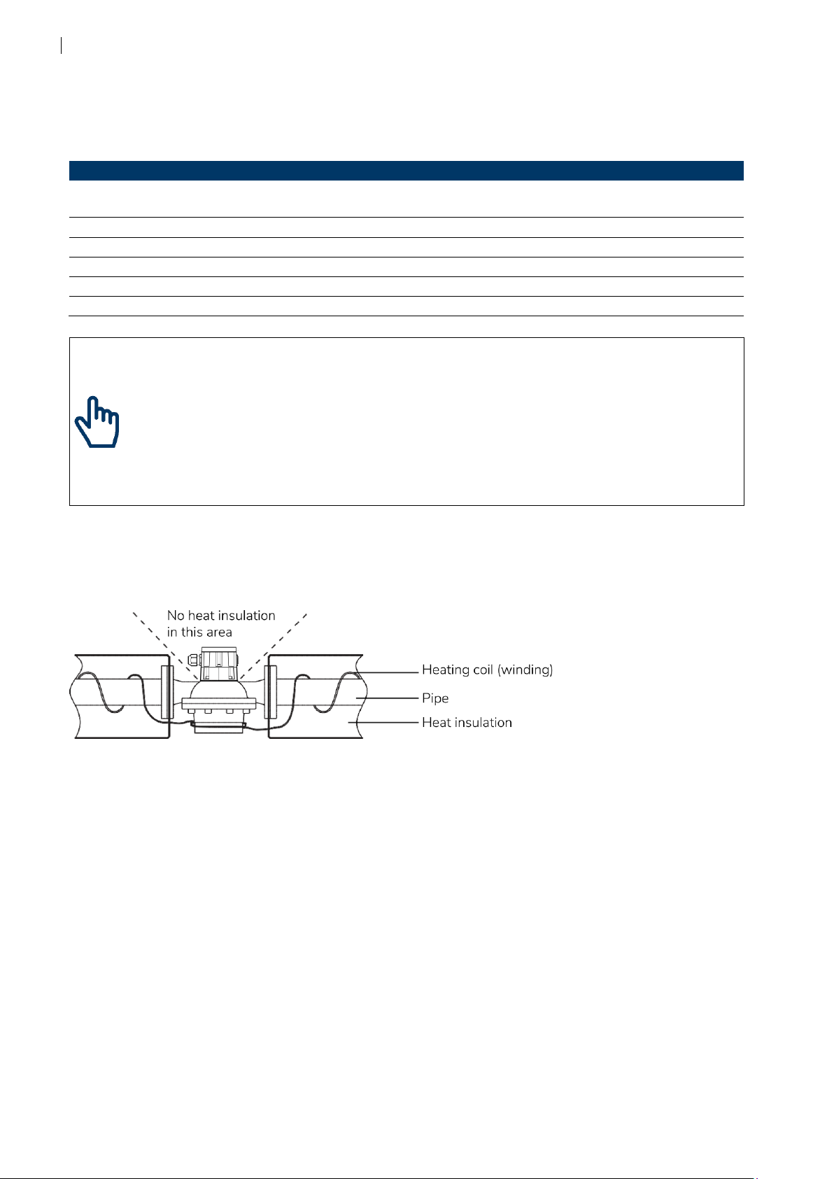
4.3 Engineering notes.................................................................................................................................................15
5Handling and operation............................................................................................16
5.1 Commissioning......................................................................................................................................................17
5.2 Display and operation.........................................................................................................................................17
5.3 Parameterizing.......................................................................................................................................................18
5.4 Main Menu..............................................................................................................................................................18
5.5 Setup menu structure..........................................................................................................................................20
5.6 Output assignment settings .............................................................................................................................22
5.7 Description of menu items................................................................................................................................24
6Maintenance and Repair ...........................................................................................27
6.1 Calibration ...............................................................................................................................................................27
6.2 Service maintenance............................................................................................................................................27
6.3 Maintenance...........................................................................................................................................................29
6.4 Spare parts ..............................................................................................................................................................30
7Troubleshooting.........................................................................................................31
7.1 Error messages VZF II / VZFA II .......................................................................................................................32
7.2 Alarm messages VZF II / VZFA II.....................................................................................................................33
8Decommissioning, Dismantling and Disposal ........................................................34
8.1 Decommissioning.................................................................................................................................................34
8.2 Dismantling.............................................................................................................................................................34
8.3 Return of materials...............................................................................................................................................35
8.4 Disposal....................................................................................................................................................................35
9Technical data ............................................................................................................36
9.1 Hardware characteristics....................................................................................................................................36
9.2 Parameterizing the VZF II / VZFA II outputs...............................................................................................38
10 Appendix.....................................................................................................................43
10.1 Dimensional drawings.........................................................................................................................................43
10.2 Default settings VZF II / VZFA II ......................................................................................................................44
11 Certificates..................................................................................................................47

2
1Safety
1.1 Intended Use
The device CONTOIL®fuel oil meter is designed and solely intended for for the flow
measurement of Diesel oil to Heavy Fuel Oil according to ISO 8217-2010.
Improper or non-intended use of the device may compromise operational reliability of the device.
The manufacturer accepts no liability for any resulting personal injury or material damage.
1.2 Notes on safety rules and symbols
The devices are designed to meet the latest safety requirements. They were tested and delivered
in a condition that ensures safe operation. Improper or non-intended use of the devices can,
however, be dangerous. Therefore, pay particular attention to the safety instructions within this
manual, which are always shown by the following symbols:
WARNING
WARNING indicates a hazardous situation which, if not avoided, could result in
death or serious injury.
CAUTION
CAUTION indicates a hazardous situation which, if not avoided, could result in
minor or moderate injury.
NOTICE
NOTICE indicates a hazardous situation which, if not avoided, could result in
property damage.
NOTE
NOTE indicates helpful tips and recommendations, as well as information for
efficient and trouble-free operation.
See technical brochure or
mounting and operating manual
QR code link to our download website

3
1.3 Safety rules and precautions
The manufacturer accepts no responsibility if the following safety rules and precautions are
disregarded:
Any modifications of the device implemented without the prior written consent of the
manufacturer will result in the immediate termination of product liability and warranty.
Installation, operation, maintenance and decommissioning of this device must be carried out
by trained, qualified specialists, authorised by the manufacturer, operator or owner of the
facility. The specialist must have read and understood this entire installation and operating
manual and must follow the instructions contained herein.
Check the mains voltage and the information on the type plate before installing the device.
Check all connections, settings and technical specifications of any peripheral devices.
Open housing or parts of housing containing electric or electronic components only when the
electric power is turned off.
Do not touch any electronic components (ESD sensitivity).
Never exceed the specified classifications for mechanical load (e. g. pressure, temperature,
ingress protection (IP) etc.).
Release the pressure in the pipe system and reduce the temperature of the medium to a safe
level for humans when carrying out any work involving the system’s mechanical components.
None of the information contained in this manual or in any other documents shall release
planners, engineers, installers and operators from their own careful and comprehensive
assessment of the respective system configuration in terms of functional capability and
operational safety.
The local labour and safety laws and regulations must be adhered to.
1.4 About the operating manual
The manufacturer reserves the right to make changes to technical data without prior notice. The
latest information and versions of this operating manual can be requested from your local dealer.
WARNING
The manufacturer assumes no liability if the instructions and procedures described
in this manual are not followed!
NOTICE
This installation manual is intended for qualified personnel and therefore does not
include basic working steps. Before operating the equipment or system, this
installation and operating manual must be completely read and understood.
Please retain this manual for future reference!

4
2Product description
Thank you for purchasing this high-quality Product.
2.1 Flow meter configuration
The CONTOIL®flow meters consist of a hydraulic part, a coupling with temperature sensor
included and an electronic display unit.
The hydraulic part determines the nominal size of the flow meter.
The flow meters are calibrated before they leave the factory. Nevertheless, for optimal results of
differential measurement, flow meters of VZFA II with either a pairing or a special linearized
calibration should be used.
Electronic display unit VZF II / VZFA II
Local electronic display unit with 2 pulse output and 1 passive analog current loop.
For details, see the dimensional drawings on page 43.

5
3Scope of delivery an accessories
The scope of delivery is described on the delivery note. Please check all components and parts
delivered promptly after receipt of goods. Transport damages shall be reported immediately on
receipt of the goods.
1 Flow meter with electronic display unit
1 Mounting and operating instruction

6
4Mounting
CAUTION
The surfaces of the device and the medium may be hot.
Risk of burns!
Carry out work only on cooled systems.
Work may only be performed by authorized specialists in accordance with the
applicable regulations.
Use appropriate protective equipment.
WARNING
The pipe and the device may be under pressure.
Risk of severe injury!
Carry out work only on non-pressurized systems.
When working on the device watch out for leaking medium.
Work may only be performed by authorized specialists in accordance with the
applicable regulations.
Use appropriate protective equipment, particularly safety goggles.
Flow meter installation
Easy access for reading the flow meter and controlling the ancillary equipment is important.
Provided that the arrow on the housing is in the direction of flow, the flow meter can be
installed in any position without any special modifications.
The electronic display unit is rotateable in 90° steps to the installed position.
Exception: upside down installation.
Flow conditioners are unnecessary.
incorrect
correct

7
NOTE
The layout of piping must ensure that the flow meter is filled with liquid at all
times and that no inclusions of air, foam or gas may occur.
Aquametro Oil & Marine recommends to install bypass valves.
The quantities from all consumers must be registered by the flow meter.
Correct layout of flow meter and accessories
If the flow meter is used for viscosities higher than 5 mPas, or if it is mounted on the suction side
of a pump, the pressure loss and the flow rate that can still be attained should be determined
with the help of the pressure loss curves provided in CONTOIL®Technical Information.
In addition, the pressure loss due to installed filters must be taken into consideration.
Select the flow meter and ancillaries according to the working conditions listed below:
Flow meters must be selected according to the maximum flow rate and not according to the
pipe diameter. If necessary, adjust the pipeline.
Flow rate (maximum expected application flow rate = maximum-continuous flow rate of flow
meter Qcont)
Material compatibility with medium
Operating pressure and temperature
Ambient temperature
Non-Return-Valves
In order to avoid backflow and draining, Non-Return-Valves must be mounted after the flow
meter. Backflow and draining can cause faulty measurements and may damage the flow meter.
Pressure shocks during operation with the flow meter must be avoided.

8
Dirt filter, Safety filter
Filters should be fitted to prevent any damage to the flow meter from impurities in the oil.
Maximum mesh width for filters
Nominal size
Flow meter type
VZO
VZOA
DN 15
0.250 mm
0.100 mm
DN 20
0.400 mm
0.100 mm
DN 25
0.400 mm
0.250 mm
DN 40
0.600 mm
0.250 mm
DN 50
0.600 mm
0.250 mm
NOTICE
The filter mounted in the flow meter inlet is only a safety filter and can not act as
a dirt filter.
Risk of malfunction or damage.
If the medium contains dirt always have a dirt filter installed upstream of the flow
meter.
Heat insulation
The display unit shall not be insulated. This could cause its permitted temperature range to be
exceeded.
The permitted temperature ranges for the flow meter must be observed!

9

10
Special requirements - differential measurements
For differential measurements, one flow meter is installed in the supply line pipe and one in
the return line pipe. The flow difference between these meters determines the consumption.
If ordered with the "differential measurement" option, VZFA II flow meters are calibrated in
accordance with the indicated supply and return flow volumes. The flow meters are labeled
“SUPPLY” (0) and “RETURN” (1). Make sure that these flow meters are installed in the correct
pipeline, i.e. the supply flow meter shall be installed in the supply line pipe and the return flow
meter shall be installed in the return line pipe.
Special requirements - ships
On ships, attention is required to ensure that the engine can continue to operate at full power
even if there is heavy filter contamination or if the flow meter is damaged. A pressure switch can
be used to switch over to the bypass and to draw attention for servicing. The engine then
continues to operate but without consumption measurements.
NOTICE
Ship classification societies require the installation of bypass pipes.
The relevant regulations must be followed.

11
Installation of the flow meter on the suction side of a pump
If the flow meter is installed on the suction side of a pump, consideration must be given to avoid
air-intake or foam.
Installation of the flow meter on the pressure side of a pump
Special requirements - filling and dosing units
For filling and dosing, the valve must be fitted between flow meter and discharge.
The shorter the pipe section between valve and discharge, the higher the accuracy.
Avoid water hammer if fast closing valve is installed.
Flushing of pipes
If the pipes are to be flushed at a later stage, stop valves shall be provided on both sides of the
flow meter.
NOTICE
Accumulation of debris will occure in front of the stop-valve during flushing.
To eliminate this, replace the flow meter with a spool piece.
Flushing Measuring

12
4.1 Mechanical installation
WARNING
Leakage or rupture due to connections being made using force.
Risk of severe injury!
Risk of substantial property damage!
Never attempt to overcome misalignments (lateral, angular, longitudinal, torsional)
using force.
Make sure the pipings are flexible enough, if not: use compensators.
Consider the effects of thermal contraction and expansion.
WARNING
Leakage or rupture due to misuse of the mounting material.
Risk of severe injury!
Risk of substantial property damage!
Regarding mechanical strength, with bolts, screws and nuts, use the prescribed
dimensions.
Use the full number of bolts, screws and nuts.
Observe the prescribed thread lubrication (grease or dry!).
Tighten the bolts and nuts in the proper sequence to the specified torque.
If using flanged connections, the correct number of connector elements must be fitted and they
must be tightened with the correct torque in accordance with the screw manufacturer’s
instructions. Comply with the permissible operating data as defined on the type plate. Make sure
that no hazardous fumes can build up in the piping and in the flow meter during commissioning,
decommissioning and dismantling. The flow meter must at all times be completely filled with
liquid during operation. Check the flow meter periodically for tightness of the connections and for
proper functioning. If work is to be done on the installation, before each intervention: release the
pressure in the installation if hazardous liquids are used, wear protective clothing and safety
goggles, place a collecting tray underneath the installation.
Preparing for installation
Check flow meters and installation material.
Compare the data of the flow meter name plate with the expected maximum conditions of the
installation. They may not exceed the flow meter specifications:
Continuous flow rate (Qcont l/h)
Maximum operating pressure (PN bar)
Maximum temperature (°C)
Appropriate connections( threaded, or flanged) and seals (gaskets)
Fasteners for the flow meter
Resistance to liquid to be metered and temperature

13
CAUTION
Unauthorized start-up while mounting
Risk of injury!
Make sure that unauthorized start-up is not possible while mounting.
Comply with the appicable working regulations during all work on the system.
NOTE
When existing systems are altered:
Take the flow meter out of operation in order to flush the system clean of debris.
Flushing information on page 11.
Trial operation
Start trial operation (without flow meter); open the stop valves slowly when doing this.
Carry out a pressure test in the plant.
Check for leaks and tightness of all bolts.
Flush the pipework until clean (flow meter out of pipeline).
Release the pressure and stop the system again.
This trial operation ensures that the pipework is tight and clean and that there are no foreign
bodies in the pipe that could damage the flowmeter.
Installing the meter in the pipe
Remove the protection plugs or caps from the flow meter (inlet and outlet).
Insert the flow meter into the pipeline in the prescribed position and flow direction. The arrow on
the flow meter should correspond with the direction of flow. Install mating flanges parallel and
without tension in the pipe.
NOTICE
Mechanical connection of flow meter into the pipe systems.
Risk of leakage!
Always use appropriate sealing material as per connection type.
Meter with
flanged ends
Meter with
threaded ends
For pipes made of copper or thin-walled steel pipes, the flow meter requires additional fastening.
Use appropriate fasteners.
incorrect

14
4.2 Electrical Installation
NOTICE
Electrical connection to the supply voltage and/or connections to other systems.
Risk of malfunction or damage!
Review of technical data, chapter 9, on page 36.
Electrical connection - Display unit options VZF II, VZFA II
Sensor area! (Sensor dome)
No cables, wires or other installation material
must be present in this area. This can lead to
incorrect measurements and damage to the
meter.
Solid state relay
RON ≤100 Ohm, RefOFF ≥10M Ohm
Umax ≤48 VAC/VDC, Imax ≤50 mA
NOTE
Wire size for terminal 1–6 is: 0.75...1.5 mm2/ 20...16 AWG.
Cable connection
1 / 2 Power supply / output current loop (passive)
3 / 4 Output 1 (passive)
5 / 6 Output 2 (passive)
7 / 8 Reserve
9 Temperature sensor Pt1000

15
Cable gland
Strain relief: Version A according to EN 62444
Thread: M25x1.5
Clamping range: 10 - 17 mm
Key width: 29 mm
Mounting of electronic display unit
NOTE
The display can be rotated +/-270° in 90° steps during installation to improve
readability.
NOTICE
Electrical connection to Pt1000 temperature sensor.
Risk of malfunction or damage!
Ensure not to pinch cable while mounting electronic display unit onto coupling.
Guide cable around sensor dome
Electronic display unit shall not be rotated more than 270° in same
direction
NOTE
Tighten bolts of electronic display housing with 2Nm of torque to the coupling.
Factory setting of outputs
Output 1: Out.1 - Volume pulses: 50 ms, 1 l/pulse
(exception: DN15 is set to 0.1 l/pulse)
Output 2: Out.2 - Volume pulse: 50 ms, 1 l/pulse
(exception: DN15 is set to 0.1 l/pulse)
Analog: disabled
4.3 Engineering notes
Parameterizing ancillary devices
Some ancillary units require programming of pulse values or frequency (see the relevant
operating instructions). Pulse values of the VZO(A) flow meters can be taken of the type plate.
The maximum frequency is calculated with the following formula:
max. flow rate in liters/hour
pulse value in liters x 3600 = frequency in Hz

16
5Handling and operation
NOTE
Modification of operation settings may result in faulty or wrong measuring results.
Multiple output functions are available, any of these functions can be used simultaneously.
2 potential-free digital outputs (Out.1 + Out.2), each freely programmable The passive current
loop is also used to power the flow meter at the same time.
Default settings:
Volume pulses; for external totalizer or monitoring systems.
Flow / Frequency; output 0...200Hz corresponding to flow rate.
Limiting switch; Switching function with programmable high and low flow rate (NO / NC).
Status switch; control functions for Errors, Alarms and Supply Voltage (NO / NC).
Analog current loop 4...20mA corresponding to actual flow rate or actual temperature of the
medium
Compensation to Norm-Volume:
Compensation to norm-volume can be turned on, this means that the volumetric expansion of
the medium is calculated using actual temperature to its normalized volume (15°C).
The following outputs will change from volume only to compensated norm-volume.
Therefore, output values will have the following functions:
Die folgenden Ausgänge wechseln von Volumen- zu Normvolumen-Signalen:
Volume pulses; for external totalizer or monitoring systems (50 % Duty cycle).
Flow / Frequency; output 0...200 Hz corresponding to flow rate.
Analog current loop 4...20 mA corresponding to actual flow rate or actual temperature of the
medium.
Mass flow calculation:
Calculation to mass flow can be turned on, this means that the normalized volume of the medium
based on base density (15°C) and actual temperature is calculated to mass / mass flow.
Therefore, the following outputs are added and can be set accordingly:
Mass pulses; for external totalizer or monitoring systems.
Mass Flow / Frequency; output 0...20 0Hz corresponding to mass flow rate.
Analog current loop 4...20 mA corresponding to actual mass flow rate.

17
5.1 Commissioning
Startup and commissioning of mechanical part of flow meter, without programming any
electronic counter (VZF II and VZFA II). Open valves slowly, fill pipework gradually. Vent the instal-
lation well.
Startup and commissioning of mechanical part of flow meter (VZO, VZOA). Open valves slowly, fill
pipework gradually. Vent the installation well.
Water hammer must be avoided in order not to damage the flow meter. Inclusions of air cause
measuring errors in all types of flow meter and can damage them during operation.
Check the tightness of the connections watch for leakages. Check if the flow rate of the
installation correspond to the specification of the flow meter.
Function check with electronic display: read the instantaneous flow value.
Should the established flow rate be greater than the specification of the flow meter (Qcont), ei-
ther a flow control valve (throttle) must be inserted behind the flow sensor or a larger size flow
meter must be used.
5.2 Display and operation
The display shows 8-digits with a decimal point or text messages using letters. Units of
measurement and additional items of information are shown with symbols.
The references to these are shown in square brackets, e.g. [o1VoLum].
Use Step key to scroll the menu and to change field values.
Use Enter key to enter submenus and to edit / confirm field entries.
Enter key
Step key
units
actual value
flow bar
options to
actual display

18
The display data and parameters are split into two menu groups:
Main Menu: displays measured data, accesses other menus, tests display segments and
displays error or alarm messages (if present).
Setup Menu: displays parameter settings for the display, output signals, additional
information about the flow meter and operating status.
When entering the access code, adjustment of parameters are possible.
5.3 Parameterizing
In order to adjust the parameters, scroll to the [SEtUP] item from the Main Menu and press the
Enter key .
No code is required to view parameters.
To adjust any parameter in the Seutp menu, the device must be unlocked ( ) with the user
code. Press both keys ( + ) simultaneously for 4 seconds until [CodE0000] is displayed.
Press Enter again and the first right digit will start flashing, which means, the unit is ready for the
entry of the first digit of the user code 1111.
Enter the first digit by using the Step key. Press the Enter key to accept the value (in our case 1)
and to move to the second right digit. Continue this way to enter all code digits.
At the end of the procedure a will be displayed. The flow meter is now in the edit mode and
parameters can be changed.
If no key is pressed within 1 minute, the device returns to the “home” display but the edit mode is
still active (15 minute timeout). Any entries that have not been completed by
pressing the Enter key are rejected.
Parameterizing the flow meter data
In order to guarantee accurate measurement, the electronic module of the flow meter
requires adjustment. During factory calibration, the data for nominal size and the exact measuring
chamber volume are entered for this purpose. These parameters cannot usually be changed
again.
If the display shows [UNCAL] the flow meter is not calibrated.
If the electronic counter has to be replaced, please mention the serial number of the defective
counter in your communication. Spare parts are set to the appropriate hardware size.
Reset of subtotalizers
To reset all subtotalizers, go to subtotalizer volume (*), press and hold both buttons for 4s until
the counter are reset.
5.4 Main Menu
The Main Menu displays most important measured data and accesses the setup menu.
The standard “Home” display of the Main Menu is the volume total [TOT], when Mass
compensation is turned on the “Home” display is mass total [TOT].
Quich return to “home”: quickly press both key simultaneously.

19
Use the Step key to scroll through all the menu items, as follows:
Mass tot
Mass Subtot
Mass Flow
Totalizer
Subtotal*
Flow rate
Temperature
Tot d Vc
Subtot d Vc
Tot H Vc
Subtot H Vc
Setup
Display Test
Tot L Vc
Subtot L Vc
Visible when mass calculation is turned on:
- Totalizer Mass
- Subtotalizer Mass
- Mass flow (actual)
Main Totalizers and displays
- Totalizer Volume
- Subtotalizer Voume*
- Flow rate Volume or Norm-Volume
- Medium Temperature
* details for resetting all subtotalizers are on the previous
page
Visible when Norm-Volume compensation is turned on:
Fuel oil Totalizers
- Totalizer distillate fuel (d) volume compensated
- Subtotalizer distillate fuel (d) volume compensated
- Totalizer Heavy fuel (H) volume compensated
- Subtotalizer Heavy fuel (H) volume compensated
or
Lube oil Totalizers
- Totalizer lube oil (L) volume compensated
- Subtotalizer lube oil (L) volume compensated
Setup Menu
- Enter to view and adjust parameters
Display Test
- Test of all display segments

20
5.5 Setup menu structure
Setup Menu: shows settings for parameters, units and output signals.
Unit vol
Unit ti
Unit °t
Unit m
dn xx
Vc x.xx
Trip res
LFC xx.xx
Comp off
Mass off
°t Limit
dH __kg/m3
o2 xx
Oil Fuel
dd __kg/m3
o1 xx
Sim off
noErrors
noAlarms
Used rng
Cal Dat
FW 4.xx.xx
CS ABCD
Serial nr
Defaults
Piston
o1 Volume o1 Flow o1 Mass o1 mFlo o1 Limit
AnA xx
o2 Volume o2 Flow o2 Mass o2 mFlo o2 Temp
AnA Flow AnA Temp AnA mFloAnA Off
CompOn
L,m3,G
h,min,s
°C,°F
kg,t,lb
yes / no
Qstart per dn
Simulation
Error codes
Alarm codes
0 Tot hours 2 ≤ Qmax1 ≤ Qcont 3 ≥ Qmax 4 last flow
U code
Cal Dat
Serial nr
15,20,25,40,50
perdn Oil Lube
dL __kg/m3
cancel LoAd CuStFW dEf SAvE CuSt
timing L1r
Ucod on Ucod off
This manual suits for next models
1
Table of contents
Other Aquametro Oil & Marine Measuring Instrument manuals

Aquametro Oil & Marine
Aquametro Oil & Marine CONTOIL DN15 Service manual

Aquametro Oil & Marine
Aquametro Oil & Marine CONTOIL VZF II DN 15 Guide

Aquametro Oil & Marine
Aquametro Oil & Marine Viscomaster User manual

Aquametro Oil & Marine
Aquametro Oil & Marine CONTOIL VZD2 Service manual

Aquametro Oil & Marine
Aquametro Oil & Marine CONTOIL DFM Series Service manual

Aquametro Oil & Marine
Aquametro Oil & Marine DOMINO ARD Series Quick start guide

Aquametro Oil & Marine
Aquametro Oil & Marine CONTOIL VZP 4 Service manual