Aquaporin ZERO Technical manual

WARNING:
This equipment requires regular maintenance to ensure the treated water’s
potability; use it in accordance with the instructions in this user guide.
INSTALLATION 6
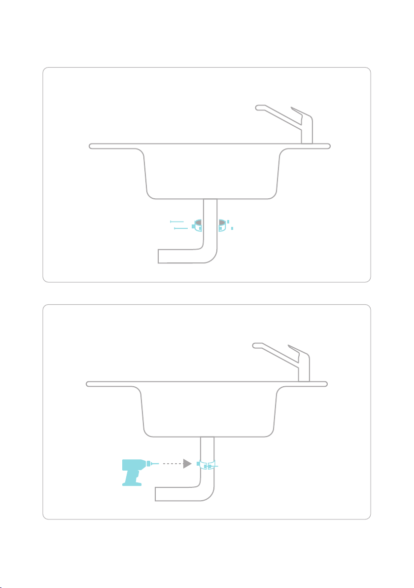
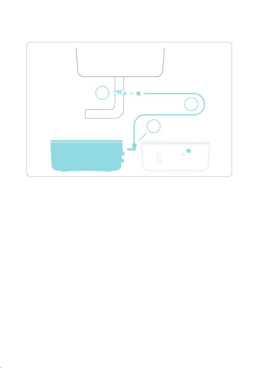
DRAIN CIRCUIT INSTALLATION 7
INLET CIRCUIT INSTALLATION 10
FAUCET INSTALLATION 14
OUTLET CIRCUIT INSTALLATION 16
TAP CIRCUIT FUNCTIONS 18
USE 19
PRE- AND POST-FILTER REPLACEMENT 20
RO FILTER REPLACEMENT 23

3
ZERO | USE AND INSTALLATION GUIDE
DIMENSIONS
15 cm
5.9 in
36 cm
14.17 in
36 cm
14.17 in

4
ZERO | USE AND INSTALLATION GUIDE
G
Pipe
8X6 mm
2 m
6.56 ft
9300733
M
Teflon Tape
/ Plumber’s
Tape
1 piece
H
Pipe ¼”
1 m
3.28 ft
9300522
A
T-fitting
F/F/M
1 piece
9400334
C
Straight M
adapter
3/8”
1 piece
9300258
B
Mini ball
valve M/F
1 piece
9400300
I
Stem
elbow ¼”
1 piece
9300728
F
Straight
female
connector
2 pieces
9300734
L
Gooseneck
faucet kit
1 piece
XO0001BN
D
Drain
clamp
kit
1 piece
1100137
J
Straight
female
adapter
1 piece
9300651
E
Stem
elbow
8 mm
2 pieces
9300735
K
O-ring
3021
1 piece
1100223
COMPONENT LIST

5
ZERO | USE AND INSTALLATION GUIDE
INSTALLATION SCHEME
drain
drain
mix
in
in
out
out
Before installation,
cover with Teon Tape /
Plumber’s Tape.

6
ZERO | USE AND INSTALLATION GUIDE
INSTALLATION
Before installation, remove the yellow IN and OUT plugs as well
as the DRAIN plug. Keep the plugs as they will be reused if the
device is relocated.
1
2
Drain plug extraction
1. Keep the collet
pressed down
2. Pull out the plug

7
ZERO | USE AND INSTALLATION GUIDE
Drain
clamp kit
1 piece
Pipe ¼”
1 piece
Stem
elbow ¼”
1 piece
D
HI
Gasket
Drain clamp kit assembly
DRAIN CIRCUIT
INSTALLATION

8
ZERO | USE AND INSTALLATION GUIDE
1/3
2/3
Drill ø 6 mm / 15/64”
DRAIN CIRCUIT INSTALLATION

9
ZERO | USE AND INSTALLATION GUIDE
3/3
D
H
I
DRAIN CIRCUIT INSTALLATION
drain

10
ZERO | USE AND INSTALLATION GUIDE
T-fitting
F/F/M
1 piece
Mini ball
valve M/F
1 piece
Straight
female
connector
1 piece
Pipe
8X6 mm
Cut length
to fit
Stem elbow
8 mm
1 piece
BCA F
G E
INLET CIRCUIT
INSTALLATION
Straight
M adapter
3/8”
1 piece
Teflon Tape
/ Plumber’s
Tape
1 piece
M

11
ZERO | USE AND INSTALLATION GUIDE
INLET CIRCUIT INSTALLATION
Before installation,
ensure that the cold
water valve is turned
off/closed
CLOSE
PLEASE NOTE!
Before installation,
cover with Teon Tape /
Plumber’s Tape.
M

12
ZERO | USE AND INSTALLATION GUIDE
1/4
2/4
A
B C
Cold water pipe
INLET CIRCUIT INSTALLATION
PLEASE NOTE!
Before installation,
cover with Teon Tape /
Plumber’s Tape.
PLEASE NOTE!
Before installation,
cover with Teon Tape /
Plumber’s Tape.
M
M

13
ZERO | USE AND INSTALLATION GUIDE
3/4
4/4
G
E
F
in
INLET CIRCUIT INSTALLATION

14
ZERO | USE AND INSTALLATION GUIDE
Fixing nut
1 piece
Toothed
washer
1 piece
Plastic
washer
1 piece
Rubber
gasket
1 piece
Spacer
with
o-ring
1+1 pieces
54321
Faucet
1 piece
For the faucet operation instructions, see page 18.
L
FAUCET
INSTALLATION

15
ZERO | USE AND INSTALLATION GUIDE
L
1
5
4
3
2
FAUCET INSTALLATION
Drill ø 12 mm / 15/32”
Drill a hole adjacent to
your regular faucet.
1/2
2/2

16
ZERO | USE AND INSTALLATION GUIDE
O-ring
3021
1 piece
Straight
female
adapter
1 piece
Pipe
8X6 mm
Use the rest
or cut to fit
Stem
elbow
8 mm
1 piece
Straight
female
connector
1 piece
KJ G E F
OUTLET CIRCUIT
INSTALLATION

17
ZERO | USE AND INSTALLATION GUIDE
out
K J G E
F
OUTLET CIRCUIT INSTALLATION
1/2
2/2

18
ZERO | USE AND INSTALLATION GUIDE
BLUE LED ashes when
the battery is inserted.
No ashing
for about 2 minutes.
RED and BLUE LED’s will ash
simultaneously for 10 seconds to
conrm the reset procedure.
1
1 32
TAP CIRCUIT FUNCTIONS
START/RESET THE CIRCUIT
Close the faucet tap, insert the battery into the circuit which will be indicated by BLUE
LED ashing, then insert the circuit into the faucet tap within 30 seconds. Now wait
about 2 minutes until the BLUE and RED LEDs both ash simultaneously for about
10 seconds. This indicates that the circuit has successfully started.
LED light sequence for successful start/reset.
ATTENTION: DO NOT MOVE THE FAUCET TAP KNOB BEFORE
THE SEQUENCE IS COMPLETED
If the reset / restart is successful, the BLUE LED ashes while your water ows from
the faucet. If the reset / restart is unsuccessful, the RED LED ashes.
If the RED LED counting circuit ashes, it indicates that the pre- and post-lters’
lifetime have almost been reached. Water can still be used but you must initiate the
process of changing the lters soon.
When the RED LED remains on, it is time to replace the pre- and post-lters – the
RED LED will be lit until the battery is exhausted. See section Pre- and post-lter
replacement for guidance. After replacing the pre- and post-lters, insert a new battery
to reset the count.
If you replace the battery before the RED LED remains on, the count will not be reset.
The reset will only happen when replacing the battery while the RED LED is on. In case
of early lter replacement, a technician is required to reset the count.
If the faucet tap is in normal operation a BLUE LED will ash during dispensing.
See the lter exchange guide on aquaporin.com/zero for more information.
2
3
4
5
7
6

19
ZERO | USE AND INSTALLATION GUIDE
USE
IF YOU HEAR A NOISE DURING FIRST USE,
PLEASE FOLLOW THIS PROCEDURE:
• put ZERO in the vertical position in order to let
the air ow out of the system
• complete at least 3 cycles of lling and emptying the tank
to condition the system
• put ZERO in a horizontal position
N.B.
The noise should disappear after some cycles and/or after some hours.
Depending on pressure there can be a sound of the tank being lled.

20
ZERO | USE AND INSTALLATION GUIDE
PRE- AND POST-FILTER REPLACEMENT
Before replacing the pre- and post-lters, turn the
cold water valve off and turn the faucet on until the
water ow stops.
CLOSE OPEN
PRE- AND POST-FILTER
REPLACEMENT
Other manuals for ZERO
2
Table of contents
Other Aquaporin Household Appliance manuals