Aquatec KC 150 User manual

Technical Manual
for installation, operation and maintenance of
Compact KC 150 - 190 - 240
Version 58 - 04.2021
Download latest manual at:
www.aquatec-watermaker.de/downloads_E.html
In case of doubt, the German ori
g
inal manual applies.
AQUATEC- Water maker,
Manufacture and distribution b
y
North-Marine Handels GmbH
Papenre
y
e 61, D 22453 Hambur
g
.
Contac
t
sup
@
aquatec-watermaker.de, Tel: +49
(
0
)
40-36850306
Web www.aquatec-watermaker.de
All contents of this manual, in particular texts, photographs and graphics are subject to German
copyright law. Copyright held by North Marine Handels GmbH. Duplication, editing, distribution and any
kind of use outside the limits of copyright law require the written approval of the author.

2
Thank you to choose an AQUATEC Watermaker for the provisioning of fresh water on your boat.
AQUATEC equipment is made from high-quality components exclusively and has proven its reliability
on long cruising-yachts. We are convinced that our product will serve you for many years without
interferences.
This instruction includes important safety information and instructions for commissioning,
operation and maintenance of the Aquatec Watermaker components. It is essential therefore, that the
responsible specialist refers to it before starting any work on the machinery as well as prior to
commissioning. Furthermore, this instruction must always be available on site.
To ensure total satisfaction, please read this user manual carefully. Warranty will be void if the installation does
not meet this requirement. Disregarding the warnings / instructions in the User Guide and incorrect installation
can lead to serious health damage or possibly the loss of the vessel.
The following symbols and their meaning must be observed throughout the manual. Please follow the
instructions and take appropriate measures.
EXPLANATION OF SYMBOLS
Warning!
Immediate danger that
can lead to serious injury
to persons or damage to
the machine or the loss of
the vessel.
Warning!
Warnings regarding electric
power equipment. Non-
observance of safety
instructions could lead to
danger of life or limb:
Attention!
Indicates an
instruction that
requires
special
attention.
Please note the following information.
Wa
r
nin
g
!
Damage to pumps and system parts due to dry running or insufficient water
supply are not covered by warranty.
Wa
r
nin
g
!
Aquatec Watermaker are designed for permanent installation on ships.
Operation of the system is only permitted with clean seawater.
Warning!
Never operate your Aquatec Watermaker unsupervised and leave the
operation only to trained persons.
Please note: If there are any leaks, the boat can fill up with water and sink,
thereb
y
endan
g
erin
g
the life of the people on board.
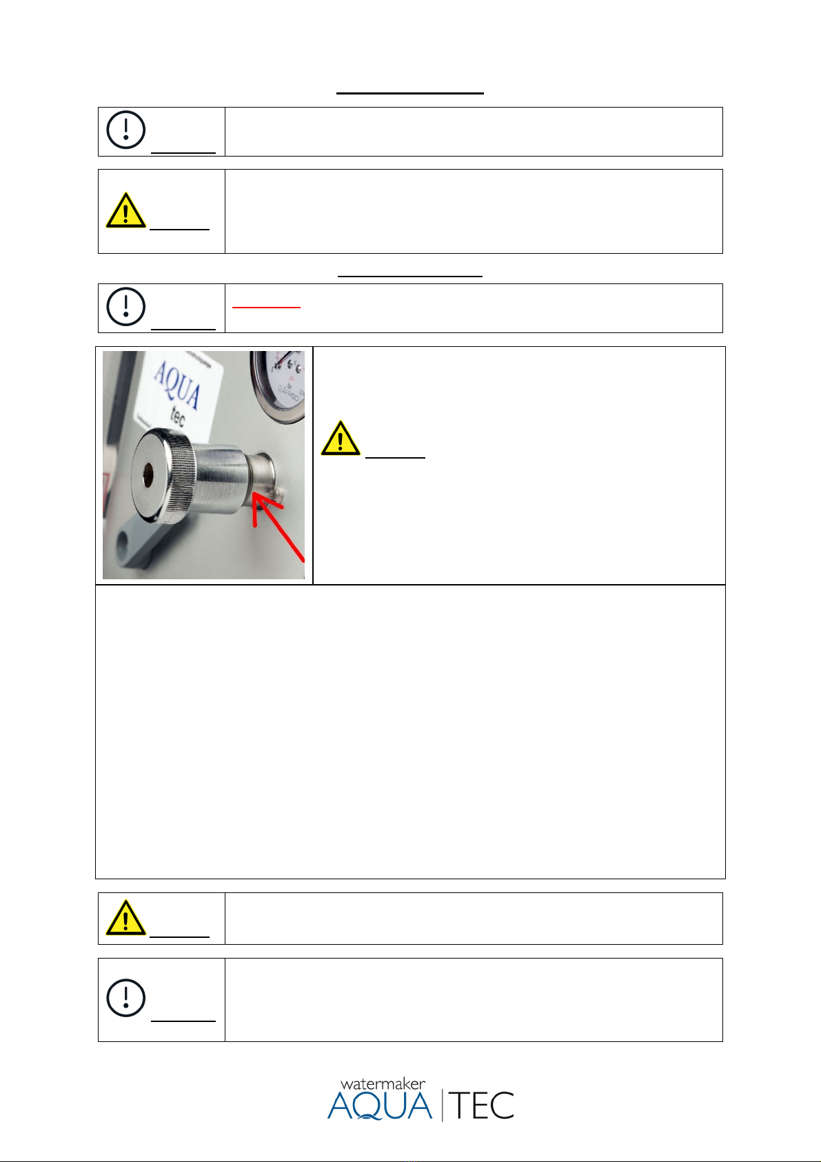
Warning!
The maximum working pressure of 55 bar (800 psi) must not be exceeded.
When exceeding the specified product water quantity (seawater with lower salt
content, brackish water
)
, the workin
g
pressure must be reduced.
Warning!
Install the high-pressure pump on a stable substrate
.
Install the high-pressure
pump in a dry area which allows an exchange of air necessary for cooling the
motor-pump unit.
The pumps may not be operated if explosive or flammable Materials are present.
Please note: The motors and pumps develop high temperatures during
operation. Touchin
g
it can cause burns.
Warning!
The installation of the hoses to the components of the system must be carried
out in compliance with the bending radii without stress and vibration (risk of
breaka
g
e
)
.
Attention!
Like any piece of mechanical equipment, the system will require inspection and
service from time to time. For easy access to enable a simple regular monitoring
and proper maintenance do not place the components in inaccessible areas.
It should be easily accessible roundly to make service and inspection work as
comfortable as possible.
Attention!
The already assembled membranes can be stored for approx. 5 months in the
sealed pressure tube, preferably cool, but preferably not above 20 ° ambient
temperature. However, we recommend installing and using the Watermaker as
soon as possible.

3
Table of contents
2 Warnings / Hints
4 Introduction reverse osmosis
5 Overview
6 - 7 Operatin
g
instructions
8 - 9 Shutdown / fresh water flush.
10 - 11 Long term preservation (mothballing), antifreeze
12 Membrane cleanin
g
13 - 15 Installation
g
uide
16 - 17 Electrical connection
18 Important: Inspection and maintenance
19 Change of membranes
20
–
21 Troubleshootin
g
22 - 23 Clampin
g
torques / Spare parts
24 - 27 Specification / dimensions
26 Scope of deliver
y
28 Connection dia
g
ram membranes
Recommendation for using your Aquatec reverse osmosis system.
Daily use is preferable to a one-time weekly use.
The system produces water with a neutral taste and very good quality.
Important: The drinking water must be bottled from the test outlet of the system during operation,
ideally after filling the on-board water tank. Only fill the required amount until the next operation of the
plant. Clean the drinking water bottle regularly.
If the product water from the on-board water tank is used as drinking water, follow-up-treatment is
recommended. No further treatment is usually necessary as service water.

4
Introduction
The principle of reverse osmosis (RO)
In natural sciences and technology, osmosis is perceived as the directed migration of molecules through
a semi permeable membrane. The chemical and physical structure of the membrane determines which
molecules are able to pass and which are not. For this reason, it is called semi-permeable, which means
as much as halfway or partial permeability.
RO Membrane
If one mixes different liquids, like in this case water with different salinities, they aim to equalize their
concentration. That way, the seawater would be thinned out and the drinking water would be enriched
with salts. The effect would be a less concentrated, homogeneous dissolution. Pouring sea- and fresh
water in equal amounts into a container where both liquids are separated by an adequate semi-
permeable membrane, there would be one side with seawater that is highly loaded with salts, on the
other side more or less “clean” water without or with little dissolved components.
The natural tendency of both liquids to equalize their salinity leads to the migration of water molecules
from the fresh water side towards the seawater side. As a result, the volume of water on the fresh water
side decreases while it increases on the seawater side. This process of osmosis takes place until the
pressure on the seawater side is in accordance with the osmotic pressure. Then it stops. In this case,
the osmotic pressure is around 30 bar.
The described process however is reversible by exposing the liquid on the seawater side to mechanical
pressure. At a pressure of 30 bar, the osmotic process cannot take place or would rather be reversed.
When pressure is increased beyond 30 bar, for instance 60 bar, water molecules from the seawater side
migrate to the fresh water side. All other components of the seawater dissolution are not able to pass
the membrane. As a result, the dissolution on the seawater side remains highly-concentrated while there
is a gain of fresh water on the other side of the membrane. This process is referred to as reverse osmosis
(R.O.)
The seawater is delivered to the pressure pipe’s entry side of a RO-system by a high-pressure pump.
The osmotic membrane is located in the pressure pipe and is merely permeable for the vehicle “water
“(solvent) and detaining the soluted substances. When the pressure difference is more than leveling out
the osmotic head, the water molecules are able to pass the membrane that works like a filter, while the
“unpurified” molecules are detained. In opposite to a classic membrane-filter, osmosis membranes do
not have continuous pores. In fact, the ions and molecules are migrating through the membrane by
diffusing through the membrane material. Inside of the membrane, the permeate-tube is located which
transports the fresh water through one of the two end caps of the pressure pipe towards the fresh water
tank. The excess seawater, now referred to as concentrate (brine), is drained off overboard through the
outlet of the pressure pipe by a pressure control valve.

5
Overview
1 6 9 11
10 3 7 8 2 5 4
1 Membranes 2 up to 4 pc. dependin
g
on the plan
t
2 three-wa
y
valve switchover test outlet / fresh water tank
3 Valve fresh water flush
4 Sediment filter (20 / 5 Micron) pre-filter sea water
5 Pressure re
g
ulation valve
6 Flow meter, shows liter/h. product water quantit
y
7 Switch feed pump
8 Switch hi
g
h pressuer pump
9 Gau
g
e feed pressure
10 Charcoal filter for fresh water flush
11 Gau
g
e workin
g
pressure

6
Operating instructions
Attention!
Do not operate your water maker with unpurified seawater (oil, chlorine or other
chemicals).
Warning!
The R.O. membranes are conserved with a dissolution that, when ingested, can
cause irritations of the gastrointestinal tract. For that reason, the product water
must not be consumed within the first 30 minutes of operating time, beforehand
it has to be drained over the test-outlet. This applies accordingly after temporary
shutdown or cleanin
g
of the membranes with the cleanin
g
chemicals.
Placing into operation
Attention!
Important: Check oil level and condition of the oil of high-pressure pump daily.
If condensation occurs (whitish discoloration of oil) change oil immediately.
1) Open the seawater intake valve (no.10).
2) The pressure control valve (no.5) in the control panel has to be
fully opened by turning counter clockwise.
Warning! Never start your Aquatec with closed pressure
control valve!
Starting with a closed valve destroys the pressure reading and
possibly essential parts of the equipment.
An open pressure control valve can be seen when the first two
threads of the valve body becoming visible by turning the
pressure control wheel.(see picture left)
3) Turn three-way valve (no. 4) according to the flow diagram to position fresh water production. Turn
three-way valve (no. 2) to position test-outlet.
4) Switch on the feed pump. The gauge (no.9, “pressure feed water”) must show positive pressure.
De-aerate the pre-filter system if necessary and control the drain water. To prefill the system, a
short fresh water flush via the onboard pressure water pump can be useful.
5) Switch on the high-pressure pump.
6) Increase the pressure at the pressure control valve (no.5) by slowly turning it clockwise to about 30
bars. Let the system work for about 30 seconds. There should not be any air pockets visible in the
system.
7) Increase the pressure stepwise up to the maximum working pressure (55 bar, 800 psi). Test the
product water by tasting from the test outlet (at daily operation, the product water should be salt-
free after about 60 seconds). By shifting the three-way valve no. 2, the product water is fed into the
fresh water tank.
8
)
Inspect the whole s
y
stem for leaka
g
es.
Warning!
Never turn the pressure regulation knob completely out while the system is
running. The pressure pushes out the parts inside, which can result in injury and
loss.
Attention!
If the system is operated in brackish water, seawater with a lower salt content or
higher water temperature the fresh water production must not exceed the
displayed value! In this case, regulate the pressure under continuous
observation of the produced amount of water until the normal level of fresh water
production is reached.
(
e.
g
. Baltic Sea about 35 bar or 490 psi
)

7
Flow diagram water production
1 Valve for circulation 7 Onboard pressure water pump
2 three-wa
y
valve product water 8 Feed pump
3 Valve fresh water flush 9 Gau
g
e feed pressure
4 three-wa
y
valve 10 Sea cock
5 Pressure re
g
ulation valve 11 Gau
g
e workin
g
pressure
6 Flow meter product water 15 Hi
g
h pressure pump
Attention!
The drinking water production changes according to the salinity, the
temperature of the seawater and the age of the R.O. membrane. The data
regarding the fresh water production apply to a salinity of 35 grams/liter at a
temperature of 25ºCelsius (77°Fahrenheit) at the new membrane.
A discrepancy up to +/- 10% also in the power consumption, especially in the
first 50 hours of operation, are usual.
At seawater temperatures below 25 ° C, the product water quantity is reduced by the following values.
Data (approx.) In %.
Water temperature 15° C - 20%
Water temperature 5° C - 35%

8
Switch off the system, fresh water flush
1) Open the pressure control valve until the plant runs without pressure.
2) Run the Aquatec several minutes to remove the concentrated salt from the membranes.
3) Turn three-way valve (no. 2) to position test-outlet.
4) Switch off the high-pressure pump first and then the feed pump.
5) Close the sea water intake valve.
6) Open valve (no. 3). The fresh water pressure pump of the boat should turn on now flush the system.
Duration of flushing time see “flushing time”.
7
)
Close valve
(
no. 3
)
to finish the fresh water flush.
Description fresh water flush
The fresh water rinse is activated by opening valve (no.3). For this, the seacock must be closed. When
that valve is open, fresh water could drain to the sea.
At least 10-15 liters of fresh water is required per membrane A charcoal filter removes any existing
chlorine inside the fresh water tank which destroys the membrane.
Attention!
The carbon filter ensures a chlorine separation up to 4 litres/minute. If necessary,
the performance of the on-board pressurized water system must be reduced to
avoid damaging the membranes by prevent chlorine. This note only applies
when chlorine is used in the drinking water tank.
Membrane and HP pump reduce the flushin
g
rate b
y
their internal resistance.
Flushing time:
The time needed for the fresh water rinse depends on the board-side performance of the fresh water
pump and the condition of the membranes and therefore cannot be stated on factory side.
Please find out the required amount of flushing water by discharging the rinsing water into a bucket
once after a normal operation (take off the hose at the thru-hull fitting) and check the salinity
constantly by tasting. During the process, stop the time to find out the time requirement of future
flushes. By collecting it in a bucket, you also find out the needed amount of flushing water.
Hint:
If there is no chlorine present in the fresh water tank, running the feed pump and HP-pump can
accelerate the fresh water flushing. Thanks to the well-known pump performance of the HP-pump, the
necessary flushing time can be precisely adjusted. Note: the onboard fresh water pump must provide
sufficient flow. Performance of AC 65- 110 / 6 liter/minute, AC 75- 135 / 11 liter/minute, AC 150- 240 /
14 liter/minute.
Attention!
Fresh water flushing of the Aquatec is recommended after each operation. It
reduced biological growth in the membrane and preserves the life span and the
reliability of the entire system.
After each operation, the Aquatec should be rinsed with fresh water. After fresh
water flushing, the system may remain unused for 7-14 days. This process can
be repeated as desired to avoid the use of chemicals.
Attention!
Prior to a longer period of shutdown (without flushing), the Aquatec has to be
preserved with the chemical no. 3 (Biocide). For instructions, see “Long term
preservation
(
mothballin
g)
of the plant”.

9
Flow diagram fresh water flush.
Note! Flushing working pressure 0 bar!!!
1 Valve for circulation 7 Onboard pressure water pump
2 three-wa
y
valve product water 8 Feed pump
3 Valve fresh water flush 9 Gau
g
e feed pressure
4 three-wa
y
valve 10 Sea cock
5 Pressure re
g
ulation valve 11 Gau
g
e workin
g
pressure
6 Flow meter product water 15 Hi
g
h pressure pump

10
Long term preservation (mothballing) of the plant (Page 1 of 2)
Description:
Prior to a longer period of shutdown, the Aquatec has to be preserved with chemical no. 3 (Biocide).
After mothballing, the plant can be shut down for 6 months, depending on the environmental conditions.
Attention!
Before preservation and longer downtime. The oil of the high-pressure pump
must be changed in order to remove any possibly existing condensation water
from the oil. This prevents corrosion of the bearings and surface of the
crankshaft
Warning!
The conservation chemical no. 3 is a Biocide. Please consider the hazard notes
on the canisters. Working with chemicals, please wear protective glasses,
breathin
g
protection and rubber
g
loves for
y
our own safet
y
.
Note!
If there is the risk of frost, the entire pressure pipe with internal membrane in
the pipe should be dismounted (after necessary preservation) and be stored
frost-proof with closed hose connections. Can the membrane not be removed
alternatively 20%- 50% glycerin in food quality can be added as an antifreeze
to the biocide at preservation. The plant has to be drained (filter housings,
pumps, hoses
)
. Remove filter cartrid
g
es.
Instruction for mothballing.
Wa
r
nin
g
!
Make sure that you follow the following instructions carefully so that no
cleaning chemical gets into your fresh water tank.
Note! Working pressure 0 bar!!!
1) Close the sea water intake valve.
2) The pressure control valve must be open. Turn the product water three-way valve (no. 2) to
position test-outlet to avoid that chemicals get into the drinking water tank.
3) Rinse the system with fresh water as described in “Fresh water flushing”.
4) Turn the three-way valve (no. 4) according to the flow diagram “Long term preservation
(mothballing) of the plant”. Open valve (no.1).
5) Dissolve the stated amount of biocide (no. 3) completely in 10 litres of water and pour it into the
tank for conservation. (To avoid negative pressure, do not close the cap tightly) As a result of the
water already in the system, (each pre-filter= 1 litre, each membrane= 1.5 litres) together with
these 10 litres, the result will now be the maximum permitted concentration of 0.5% by weight.
A level teaspoon corresponds to 5 grams Biocide (Natriummetabisulfit).
6) Switch on the feed pump and the high-pressure pump. Let the Biocide circulate through the
system for about 2-3 minutes. Perform possibly exiting the test outlet liquid back into the
preservative tank.
7) The Biocide in the tank can be discharged overboard after turning the three-way valve (no. 4). It
should be noted that the s
y
stem
g
ets no air. Switch pumps off.
KC 150 max. 75 gr. Amount of biocide KC 240 max. 90 gr.
KC 190 max. 82 gr.
Attention! For preservation times of approx. 2 months, half of the chemical is sufficient.

11
Long term preservation (mothballing) of the plant. (Page 2 of 2)
Hint:
In order to avoid possible deposits in the pumps, it is advantageous after preserving the membranes to
remove the high-pressure hose at the outlet of the HP pump and to wash out the system with fresh
water again, this time without the connected membrane.
A standard 1/2” hose can be used for this purpose, which should be fitted onto the HP threaded
connector of the high-pressure pump to drain the water out into a bucket. Then drain the all the water
from the pump, which is important if there is a risk of frost, if possible it is also preferable to blow
pressurized air through it in the direction of flow, for this purpose remove the sea water intake hose from
the HP pump.
Leakage of the preservative liquid from the pressure pipes is harmless. It is important that membranes
with the preservative liquid are well moistened and cannot dry out.
Warning!
At every recommissioning after cleaning or mothballing, divert the product water
over the test-outlet for the first 30 minutes to rinse the chemical completely out
of the s
y
stem.
Flow diagram long term preservation (mothballing) and cleaning
Note! Working pressure 0 bar!!!

12
Membrane cleaning.
Description:
When the fresh water production decreases more than 15 %, the membrane should be cleaned
chemically.
Warning!
Cleaning chemical no. 1 is alkaline and cleaning chemical no. 2 is an acid.
Please consider the hazard notes on the canisters. Working with chemicals,
please wear protective glasses, breathing protection and rubber gloves for your
own safet
y
. Do must not mix different chemicals.
Instruction for cleaning of membranes.
Wa
r
nin
g
!
Make sure that you follow the following instructions carefully so that no cleaning
chemical gets into your fresh water tank.
Note! Working pressure 0 bar!!!
1) Close the sea water intake valve.
2) The pressure control valve must be open. Turn the product water three-way valve (no. 2) to
position test-outlet to avoid that chemicals get into the drinking water tank.
3) Rinse the system with fresh water as described in “Fresh water flushing”.
4) Turn the three-way valve (no. 4) according to the flow diagram “Long term preservation
(mothballing) of the plant”. Open valve (no.1).
5) Blend about 10 liters warm chlorine-free fresh water, temperature app. 25° Celsius (77°
Fahrenheit), with chemical no. 1 (Alkaline), according to the instructions on the package and pour
it into the tank for conservation. (To avoid negative pressure, do not close the cap tightly) Since
there are about 1,5 litre of water already in each membrane and 1 litre of water in each filter,
please add the according amount of chemical to the water that has to be blended in every
membrane and filter.
6) Switch on the feed pump and the high-pressure pump. The unit is run for about 5 minutes to
circulate the solution through the membrane. Temperature of the solution must not exceed more
than 45° Celsius. Then allowed to rest for an hour, and then run again for 5 minutes. Perform
possibly exiting the test outlet liquid back into the preservative tank.
7) The chemical in the tank can be discharged overboard after turning the three-way valve (no. 4).
It should be noted that the system gets no air. Switch pumps off.
8) After this, the system is put back into service, unpressurized, and run for 15 minutes or so to
clear out the cleaning solution, before being returned to regular service. Once again, the initial
product water will need to be discharged for 30 minutes over the test outlet.
9
)
If there is no chan
g
e in freshwater output, repeat the procedure 1 to 7 with chemical no. 2
(
Acid
)
.
Attention!
Prior to a longer period of shutdown, the Aquatec has to be preserved with
Biocide after cleaning and flushing.
Warning!
At every recommissioning after cleaning or mothballing, divert the product water
over the test-outlet for the first 30 minutes to rinse the chemical completely out
of the s
y
stem.

13
Installation guide page 1
Attention!
The already assembled membranes can be stored for approx. 5 months in the
sealed pressure tube, preferably cool, but preferably not above 20 ° ambient
temperature. However, we recommend installing and using the Watermaker as
soon as possible.
Warning!
Hose connections below the water line should secured with 2 hose clamps.
All hose clamps must check time to time and tighten if need.
During assembly of the hose nozzles and fittings, few windings of Teflon-tape
have to be wrapped around the screw thread against screw direction as tightly
as possible. The fittin
g
s ma
y
not be screwed too ti
g
htl
y
in the filters or valves.
Thru-hull fitting, Strainer and feed pump
Install a thru-hull fitting and sea-cock, preferably deep under water line. The best place is about mid-
ships behind the keel. Install strainer and feed pump close as possibly to the sea-cock.
Attention!
To avoid mechanical stress, do not mount the strainer directly to the sea-cock.
The thru-hull fitting, coarse filter and the feed pump have to be located in an area
that will always be under the waterline when the boat is used under normal
running conditions.
In order to avoid accumulation of air, if possible, install hoses moved upward
from the thru-hull fitting to the filters and up to the high-pressure pump.
From the sea-cock outlet to the feed pump inlet, the installation must be
horizontal or better rising. In order to stay as deep as possible below the
waterline, a 90 ° hose nozzle at the sea-cock outlet can be helpful.
Attention!
Avoid connecting to an existing inlet e.g. Main machine air conditioning.
Common operation is usually not possible because the existing hose cross-
sections prevents sufficient inflow.
Attention!
The feed pump must be flooded before turn on, otherwise the bearings will be
destroyed by drought. The system has to be fully de-aerated by means of the
feed pump. To allow any air to escape, switch the pump on and off few times
and open-air release valve at pre-filter. The system can also be vented by a
short fresh water flush.
Mounting position of the feed pump
OK OK not permitted
Warning! Do not connect the feed pump directly
to a filter housing, tap or similar (risk of breakage).
Only connect to other components with the enclosed
hose nozzles and hose.
Permissible system pressure fresh water flush:
Feed pump MD 40, 115 or 230V, 2 bar.
Feed pump B-C20/A, 400 or 440V, 3 bar.
(If necessary, use pressure reducer.)
The following installation position must be observed in
order to make it difficult to set deposits and to allow the
escape of air.
Attention!
Depending on the used thru-hull fitting, hull shape and speed, the inflow of
seawater can be hampered or even be impossible. Damages to the plant due to
insufficient or missing seawater inflow will not be covered by the warranty or
g
uarantee.
Filter housing
For a good sealing of the filter housing, please lubricate the O-rings in the filter bowls with acid-free
silicone grease.
Connection of the seawater inflow
Connect the feed pump with a hose 3/4“=19 mm inner diameter to the access (A3) of the plant.

14
Installation guide page 2
Connection concentrate (brine)
Connect the access (A4) of the plant to a thru-hull fitting on-board with a hose 1/2“=13 mm inner
diameter.
Wa
r
nin
g
!
This on-board outlet must be above the waterline and must not be lockable.
The material for the thru-hull must not be made of acetal.
Product water
Connect the product water-connection (A1) with the drinking water tank on-board. Connect the product
water-connection (A2) with the test outlet on-board.
Hose 1/2“= 13 mm inner diameter.
Wa
r
nin
g
!
Never block the product water line (valve etc.). This damages the membrane
and leads to bursting of the product water line.
Advice:
A good place for the test-outlet is the sink or basin, where it can be installed by an additional water outlet
without cut off cock.
At this position, an easy control of the product water is possibly, furthermore you can bottle your drinking
water here directly. This ensures that the quality of the drinking water will be best, since it does not have
to follow a detour over the drinking water tank on-board.
Hose connection
Nr.
A
nschlussbeschreibun
g
Hose inside diameter
A
1 On-board water tank 1/2" = 13 mm
A
2Test outlet and fillin
g
of trinkin
g
bottles 1/2" = 13 mm
A
3Feed, commin
g
from feed pump 3/4" = 19 mm
A
4Concentrate
(
Brine
)
Drain overboard 1/2" = 13 mm
A
5Onboard pressure water s
y
stem 1/2" = 13 mm
A
1
A
2
A
3
A
4
A
5

15
Installation guide page 3
Attention!
If the product water inlet is installed below the tank waterline chlorinated water
(that possibly entered the tank at the last shore water fill up) might flow back
from the tanks into the membranes. As chlorine destroys the R.O. membranes,
a return flow from the tank has to be avoided. A return from the water tank is not
possible if the 3-way valve no. 2 in the control panel is switched to the test outlet
position.
A
non-return valve must not be used.
Fresh water flush:
Connect your pressurized water system on-board with the charcoal filter of the plant with the
connection (A5). Hose 1/2“=13 mm inner diameter.
Warning!
In order to avoid damaging the feed pump during fresh water flushing via the
onboard pressurized water system, observe the permissible system pressure.
Feed pump MD 40, 115 or 230V, 2 bar.
Feed pump B-C20/A, 400 or 440V, 3 bar.
A
pressure reducer ma
y
need to be installed in front of the flushin
g
connection.
Tank for membrane conservation and cleaning
The tank has to be mounted above the feed pump to ensure the
flow to the plant. If this is not possible, an additional feed pump
has to be installed.
The tank can be fastened to any plane surface with the help of
the enclosed webbing and the plastic long eyelets.
If necessary, the tank can be provisionally connected and
stored separately if necessary.
For pressure equalization, you find a 2 mm hole in the center of
the tank cover.
An oblique mounting from the tank allows complete emptying
(1) Flow to valve no. 1
(2) coming from pressure valve
(3) over board
(4) Three- way- valve no. 4
(5) 13 mm hose connection.
(6) Webbing tank mount.
(7) Shown short hose No. 7 must
be installed to avoid air-bubbles
during circulation.

16
Electrical circuit diagram
Wa
r
nin
g
!
Danger for life! It is obligatory that an electrician has to make the connection.
Incorrect connection is dangerous to life.
Warning!
Danger for life! For all work on electrical components, the entire system must
be switched off and a message must be left on the shutdown device.
Connection cables, fuses and possibly necessary on-board main power switch of the distribution on
board to the system are not included in the scope of delivery and have to be supplied on-board.
The connection cable of the plant has a length of 1 meter.
Required cable cross-sections up to 10-meter cable length, longer wires have to be enlarged:
From board’s main distribution to junction box:
230 Volt 50 Hz: 3 G 2.5 mm² (AWG 13) / 115 Volt 60 Hz: 3 G, 4 mm² (AWG 11)
400 Volt 50 Hz: 3 G 1.5 mm² (AWG 15)
Supply line from junction box to the feed pump: 3 G x 1 mm² (AWG 17)
Fuse:
Single phase 230 Volt 50 Hz, 16 amps
Single phase 115 Volt 60 Hz, 32 amps
3 phase 400/440 Volt 50/60 Hz, 10 amps
Single phase 230 Volt 50 Hz or 115 Volt 60 Hz.

17
Electrical circuit diagram
3 phase 400 / 440 Volt 50/60 Hz.
AC motor connections diagrams
Single phase 115 or 230V 50/ 60 Hz. Run capacitor
only (BK) without start capacitor. Direction of rotation
CLOCKWISE as seen on the drive-end
.
Single phase 115 or 230V 50/ 60 Hz. Run capacitor
(BK) and start capacitor (Ak). Direction of rotation
CLOCKWISE as seen on the drive-end
Three-phase 400V 50Hz (standard) or 440V 60 Hz.
3 wire WYE connections. Direction of rotation
CLOCKWISE as seen on the drive-end.
Three-phase 230V 50Hz or 208V 60 Hz (option).
3 wire DELTA connections. Direction of rotation
CLOCKWISE as seen on the drive-end.
The electric motor protective earth (PE) connection is located at the bottom of the electric motor
connection box (Phillips screw).

18
Inspection and maintenance
Attention!
Important: Check oil level and condition of the oil of high-pressure pump daily.
If condensation occurs (whitish discoloration of oil,
due to
continuous operation,
warm environment
)
chan
g
e oil immediatel
y
.
In operation, regularly check all hose connections and hp pump for leaks.
Instructions for changing the oil
of high-pressure pump:
The oil can be drained via the drain plug
at the rear of the crankcase. The drain
plug (wrench size 17 mm) is sealed with
a reusable O-ring (10.82 x 1.78 NBR 70).
Alternatively, the oil can be extracted
through the oil dipstick opening using a
suction pump.
Dipstick full
screwed into
crankcase
Öl level
middle of
crankcase
Filter Maintenance Time interval
Coarse filter Cleaning as required
Prefilter Replacement of filter elements as required
Charcoal filter Replacement of filter element every 3 months
High-pressure
pump
up to 25°C engine oil SAE 10-40
over 25°C and continuous duty:
gear oil SAE 80W-90
quantity 0,36 litre = mid sight glass
initial oil change after 50 hours, then
Every 300 operating hours at the latest
or once a year. Eearlier when the oil
gets a white color by condensation
water.
Pressure regulation valve
Service pressure regulation valve.
Maintenance is limited to cleaning and
silicone grease lubrication after 12- 24
months.
The O-ring (5), (7,5x2 NBR 70), has only to
be changed in case of leakage.
To take the pressure pin out of the valve
body, unscrew the adjusting knob (1). Then
take off the spring (2) with pressure disk (3).
Now you see the pressure (4) pin with a M3
tapped hole, pull it out by screwing in a M3
screw.
Note: Seal the ¼ “connection thread for
pressure gauges and HP connection with
Loctite 2701.
5 4 3 2 1

19
Replacement of membrane
Warning!
The membrane is preserved with a chemical. During unpacking and inserting,
please wear protective gloves for your own safety. On contact with the
preservative liquid, the affected skin areas have to be rinsed thoroughly with
water.
Attention!
To avoid that the new membrane dries out, it may only be removed from the
plastic packaging just before commissioning the plant. The manufacturer's
label on the membrane must not be removed.
Before installing a new membrane, the accompanying rubber V-cup
seal must be mounted on the side of the planned sea water entry.
(Depending on the manufacturer, the ring could already be mounted.)
In doing so, the open side of the V-ring must point toward the sea
water entry side.
For easy installation, all sealing rings and membrane connectors
should be greased with a light coating of glycerine or Vaseline.
Note!
The product water connection can be located on any side of the pressure tube
and is independent of the flow direction seawater.
Demounting the membrane:
For demounting the membranes, screw off the screws M6x20 at both ends of the AQUATEC pressure
vessel. (Screw tightening torque for the holding clips 3 Nm). Then take off the stainless-steel holding
clamps. Push the end caps in a little before pulling them out to loosen the possibly stuck O-rings.
Thereafter, pull the end caps out of the pressure pipe with a slight pull at the stainless steel-fittings of
the pressure hoses and slightly sidewise movements.
The membrane has to be shoved out of the pressure pipe in flow direction of sea water, because the
dihedral rubber V-ring of the membrane prevents lateral movements against the flow direction.
According to this, during assembly, the membrane has to be shoved into the pressure pipe in flow
direction. When mounted, necessarily watch the O-rings to avoid damage. Before installation of the
membranes, first fit the end cap on the side of the concentrate in order to thereupon shove the
membrane against this cap.
Seawater Concentrate (brine)
Product water
10 98
7
6
5
4
3
21
Pressure vessel
Membrane
1) O-ring
2) O-ring
3) End cap
4) Pressure ring
5) Retaining clip, A 1x
6) Retaining clip, B 2x
7) Product water
8) High pressure fitting
9) Secure clip
10
)
Screws M6 2x
Rubber V- cup seal, the open side must point toward the sea water entry side.
Product water

20
Troubleshooting
Wa
r
nin
g
!
Noisy operation, vibrations, unsteady pressure.
Prolonged operation with the above error leads to failure of other components.
Nois
y
operation, vibrations, unstead
y
pressure.
Air in system
Intake clogged
Prefilter dirty
Feed pump defective
Valve defective or soiled
Pressure re
g
ulation valve dirt
y
To bleed air from the system a fresh water flush
via the on-board pressurized water system is often
optimal for removing existing air from the system.
Clean intake
Clean or replace filter
Replace feed pump
Open valve caps and check valves, replace valves
Clean valve
Production falls
Less voltage
Membrane defective or dirt
y
Check voltage direct at motor connections
Clean or replace membrane
Motor does not turn.
Motor drones
No voltage, fuse defective
Motor protection switch activated due to overload
Motor protection switch activated, no overload
Open pressure-valve, motor capacitor defective
Check voltage, replace fuse
Reduce pressure
A
d
j
ust or replace motor protection switch
Motor protection switch located inside connection box
Oil leaka
g
e between pump head and crankcase
Crankcase
g
asket rin
g
s defective Replace
g
asket rin
g
s
Water leaka
g
e between pump head and crankcase
Plunger(s) defective / o-rings plunger defective
HP / LP seals defective
Replace plunger(s)/ replace o-rings
Replace seals
Water in pump case
Hi
g
h humidit
y
(
mostl
y)
, wron
g
oil. Reduce oil chan
g
e interval, use ri
g
ht oil
None or large fluctuations in pressure, simultaneously loud
noise and a strongly vibrating high pressure hose are
indications of usually a disturbed inlet with air in the system,
also a defective or only dirty valve of the high-pressure pump
is possible.
The fault is in one of the 6 valves in the pump head. Which
of the 6 valves is causing a problem is not visible from the
outside. To repair the error, unscrew the 6 hexagonal 22 mm
or 19 mm screws to take out the valves. Since the smallest,
barely visible piece of dirt can lead to this problem, it is often
the case that no visible dirt can be seen. Often, dismantling
and reassembling the valve is enough to resolve the failure.
Occasionally, the valve must be replaced even though no
fault can be seen. This error may also occur after prolonged
downtime.
Before the valves are removed, it sometimes helps to
operate the system at lower pressure for several minutes to
remove the dirt.
Note: Possibly, the pressure control valve can also be dirty.
Note!
Grease the thread of the valve screws with metal-free anti seize paste for
stainless to prevent seizure.
serial number
Valve screw
O-ring
Valve bod
y
Valve spring
Valve
p
late
Valve seat
O-
r
in
g
Other manuals for KC 150
1
This manual suits for next models
5
Table of contents
Popular Water Dispenser manuals by other brands

Elkay
Elkay LK4595 FTN Series owner's manual

Culligan
Culligan IC-100 use and care manual

Viessmann
Viessmann Vitovalor PA2 Installation instructions for contractors

Escowa
Escowa UNDERCOUNTER Installation, user and maintenance manual

Toro
Toro Aqua-Clear ACS-218-12VDCL Important safety instructions

Pentair
Pentair Riva Viridion user guide

Everpure
Everpure Water Filter and Cartridge QL2-OW200L Specification sheet

Pentair
Pentair Fleck 6700XTR Service manual

Pelican
Pelican PC600 owner's manual

Halsey Taylor
Halsey Taylor HVRBLFR Series owner's manual

Alphacool
Alphacool Apex RAM X4 manual

True blue power
True blue power TB-30 Installation and operation manual