manuals.online logo
Brands
  1. Home
  2. •
  3. Brands
  4. •
  5. Master Water Conditioning
  6. •
  7. Water Dispenser
  8. •
  9. Master Water Conditioning MCA Series User manual

Master Water Conditioning MCA Series User manual

This manual suits for next models

4

Other Master Water Conditioning Water Dispenser manuals

Master Water Conditioning MP-MCA-30T User manual

Master Water Conditioning

Master Water Conditioning MP-MCA-30T User manual

Master Water Conditioning MP-MCA-45T User guide

Master Water Conditioning

Master Water Conditioning MP-MCA-45T User guide

Master Water Conditioning MP-MBA-15T User manual

Master Water Conditioning

Master Water Conditioning MP-MBA-15T User manual

Popular Water Dispenser manuals by other brands

IBC Water AST0715MP-960 Installation & operating instructions

IBC Water

IBC Water AST0715MP-960 Installation & operating instructions

Lancaster Water Treatment X FACTOR LX15 Series Installation, operating and service manual

Lancaster Water Treatment

Lancaster Water Treatment X FACTOR LX15 Series Installation, operating and service manual

Elkay EMABF8 Series Installation & use manual

Elkay

Elkay EMABF8 Series Installation & use manual

Oasis Osmosis Home installation manual

Oasis

Oasis Osmosis Home installation manual

Monarch Water ULTIMATE MINI AQUA HE install guide

Monarch Water

Monarch Water ULTIMATE MINI AQUA HE install guide

Haier HLM-109B instruction manual

Haier

Haier HLM-109B instruction manual

GE GXOF18G Owner's manual and installation instructions

GE

GE GXOF18G Owner's manual and installation instructions

Kenmore 625.385560 UltraFilter 650 owner's manual

Kenmore

Kenmore 625.385560 UltraFilter 650 owner's manual

Aries Hydra DI Operation & maintenance manual

Aries

Aries Hydra DI Operation & maintenance manual

Avanti WD31EC instruction manual

Avanti

Avanti WD31EC instruction manual

GE GNCF02H owner's manual

GE

GE GNCF02H owner's manual

Avanti WD360 instruction manual

Avanti

Avanti WD360 instruction manual

ProFlo PFB Series Installation & operation manual

ProFlo

ProFlo PFB Series Installation & operation manual

Frakco Travelsoft RV 2400HD Operation instructions

Frakco

Frakco Travelsoft RV 2400HD Operation instructions

Aqua Essentials Borg & Overström B4 user guide

Aqua Essentials

Aqua Essentials Borg & Overström B4 user guide

KENT 11063 Instruction handbook

KENT

KENT 11063 Instruction handbook

Calmat Plus user manual

Calmat

Calmat Plus user manual

Igloo MWC529 instruction manual

Igloo

Igloo MWC529 instruction manual

manuals.online logo
manuals.online logoBrands
  • About & Mission
  • Contact us
  • Privacy Policy
  • Terms and Conditions

Copyright 2025 Manuals.Online. All Rights Reserved.

MCATime Clock Series
Residential Softeners
February 2011 Version
MASTER
Water Conditioning Corp.
Installation and Operation Manual
Table of Contents
Page
No.
Topic Description
1
Model # and Packaging
Packaging Information
Component Packaging
Description
Packaging Description
2
Softening System
System Positioning
MCA Control Valve
Attaching Valve to Tank
3
MCA Control Valve
Attaching Valve, cont’d
Service & Drain Piping
Drain Piping
4
Service & Drain Piping,
General Installation Layout
Drain Piping
5
System Schematic
Piping Layout
6
Electrical Supply
Electrical Requirements
Brine Tank / Brine Tubing
Brine tank w/shut off
7
Filling Softener with Water
Details for Filling Softener Tank with
Water
8
MCA Control Valve Timer
Setting the MCA Timer
9
Final Check
Final Installation Check
Manual Regeneration
Instructions for Manual Regeneration
10
Bypass
Bypass Operation
11
Troubleshooting
Problem/ Cause / Solution
12
Troubleshooting
Problem/ Cause / Solution
13
Troubleshooting
Problem/ Cause / Solution
14
Troubleshooting
Problem/ Cause / Solution
15
Troubleshooting
Problem/ Cause / Solution
16
Error Code Troubleshooting
Problem/ Cause / Solution
17
Valve Parts List
Part Numbers List
18
Valve Parts List
Part Numbers List
19
Valve Parts List
Part Numbers List
20
Valve Parts List
Part Numbers List
21
Valve Parts List
Part Numbers List
22
Warranty
Warranty
1
Installation and Operating Instructions for
MCA CONTROL
Top Mount Water Softener
Model #:
_______ MCA-30T 1.0 CF Water Softener
_______ MCA-45T 1.5 CF Water Softener
_______ MCA-60T 2 CF Water Softener
_______ MCA-75T 2.5 CF Water Softener
Shipping Carton Description / unit:
# of
cartons
Contents Description
1
Mineral tank
Distributor pipe installed
1
Brine tank
464 shutoff valve assembly. *NOTE:
MCA valve is shipped in brine tank.
1
MCA control
valve
MCA timer and backwash flow control
and bypass with 1” copper or pvc
connection
C-800
Pre-loaded @ factory
NOTE: THIS SOFTENER IS NOT INTENDED TO BE USED FOR TREATING WATER THAT
IS MICROBIOLOGICALLY UNSAFE OR OF UNKNOWN QUALITY WITHOUT
ADEQUATE DISINFECTION WHETHER BEFORE OR AFTER THE SYSTEM.
2
Water Softener Positioning:
1. Place water softener in desired position, far enough from walls and
other obstructions to allow for servicing the unit.
2. Place the water softener within reasonable access to a grounded
115V/60 HZ circuit and a legal drain line connection.
MCA Control Valve:
1. When facing the front of the MCA timer, the inlet connection is
located on the right and the outlet connection is on the left. The
control valve's inlet and outlet connections are either 1” copper or
PVC equipped with split ring and nut.
Front View Top View
2. Turn the control valve upside down and ensure that the control valve
distributor o’ring is in place. Use silicone lubricant on the o'ring.
**DO NOT USE PETROLEUM!**
**USE ONLY SILICONE **
3. Place the control valve onto the distributor pipe and into the tank
opening.
4. Thread the control valve hand tight . Do not overtighten.
5. Locate the bypass valve assembly that is packaged with the
control valve. The bypass valve has two red handles that
indicate flow direction, two threaded connections for the tail
piece kit and two o’ring seal connections with nuts for the control
Control Valve
3
valve. Align the insert connection ends with o’ring seals and
nuts to the inlet and outlet connections of the control valve.
Hand tighten the nuts. DO NOT OVERTIGHTEN THE NUT!
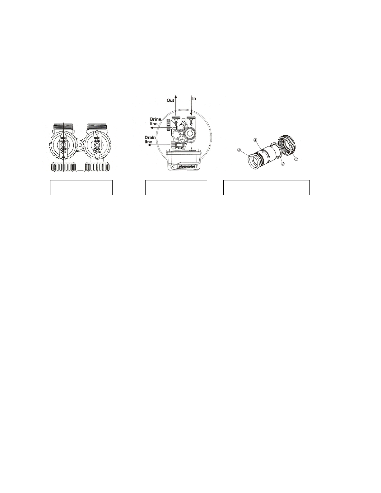
6. Locate the tail piece kit that is packaged with the control valve.
The standard tail piece kit is 1” copper with optional 1” PVC or ¾”
copper kits available as a special order. Each tail piece,
o’ring, split ring and nut is presassembled at the factory. Align a
tail piece assembly to the bypass valve threaded inlet and insert
until the nut can be tightened. Hand tighten the nut because
excessive tightening will damage the assembly. REPEAT THE
PROCEDURE FOR THE OUTLET CONNECTION.
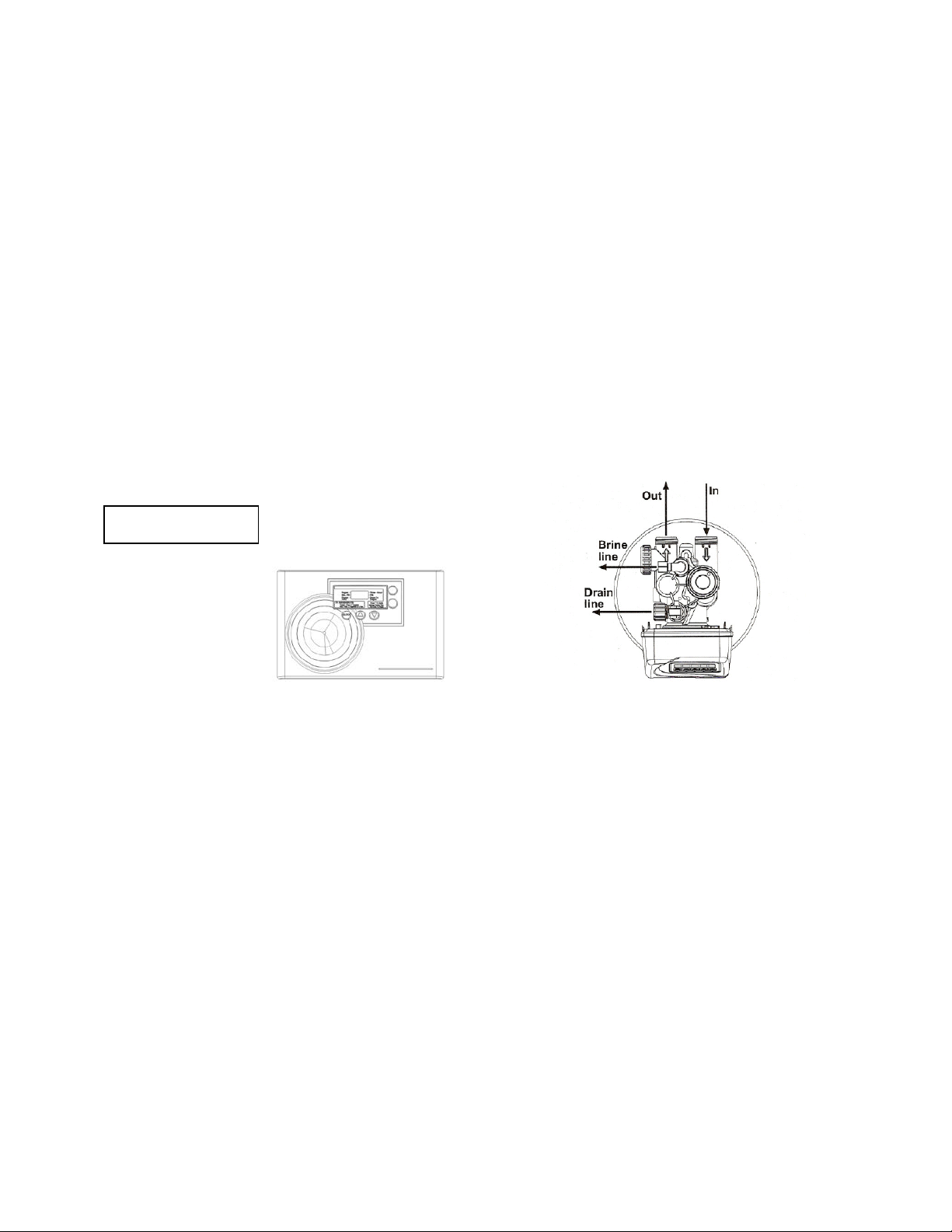
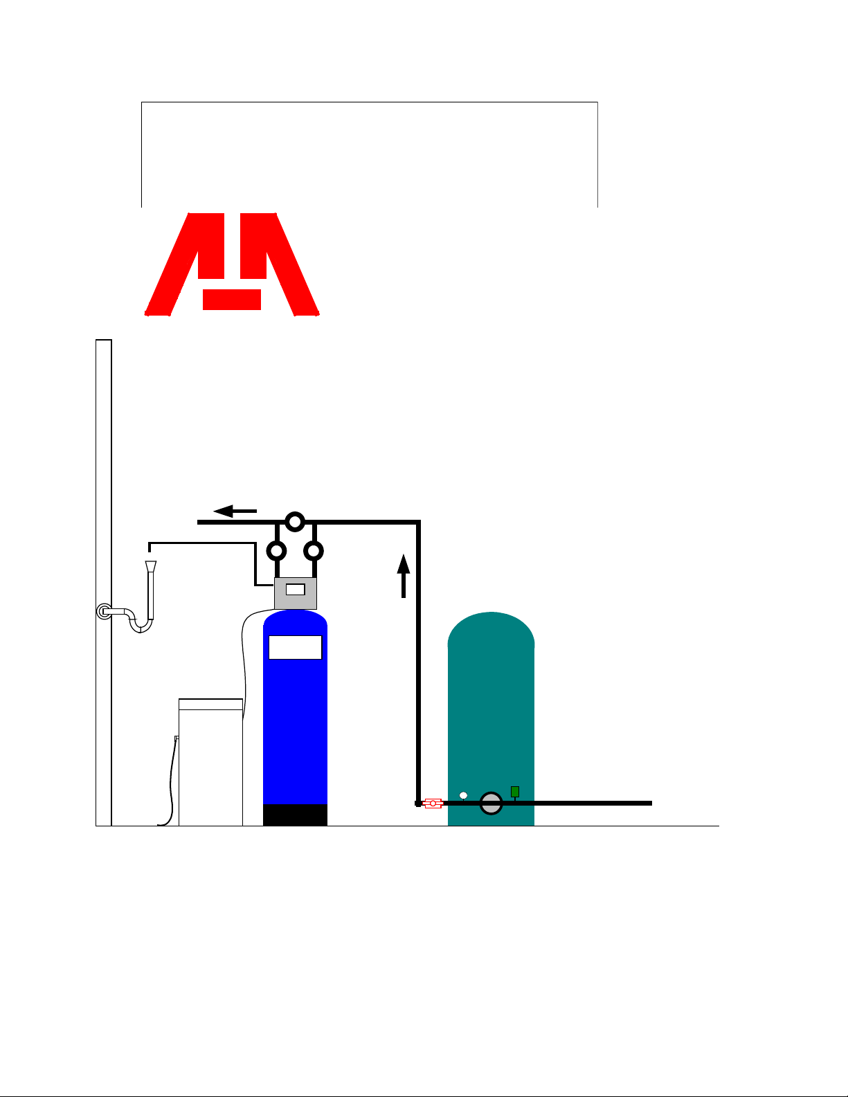
Service and Drain Piping:
1. Pipe water softener into the service lines .The inlet and outlet
connections of the control valve are 1” copper or PVC and are
located on the back of the valve body. As you face the timer the inlet
is on the right and the outlet is on the left. Always follow local
plumbing codes when installing our water treatment equipment.
2. If sweat fittings are used, be sure soldering is done in such a manner
as not to allow heat to reach the control valve or bypass. (If
Schedule 80 PVC is used make sure to follow the proper primer and
solvent instructions.)
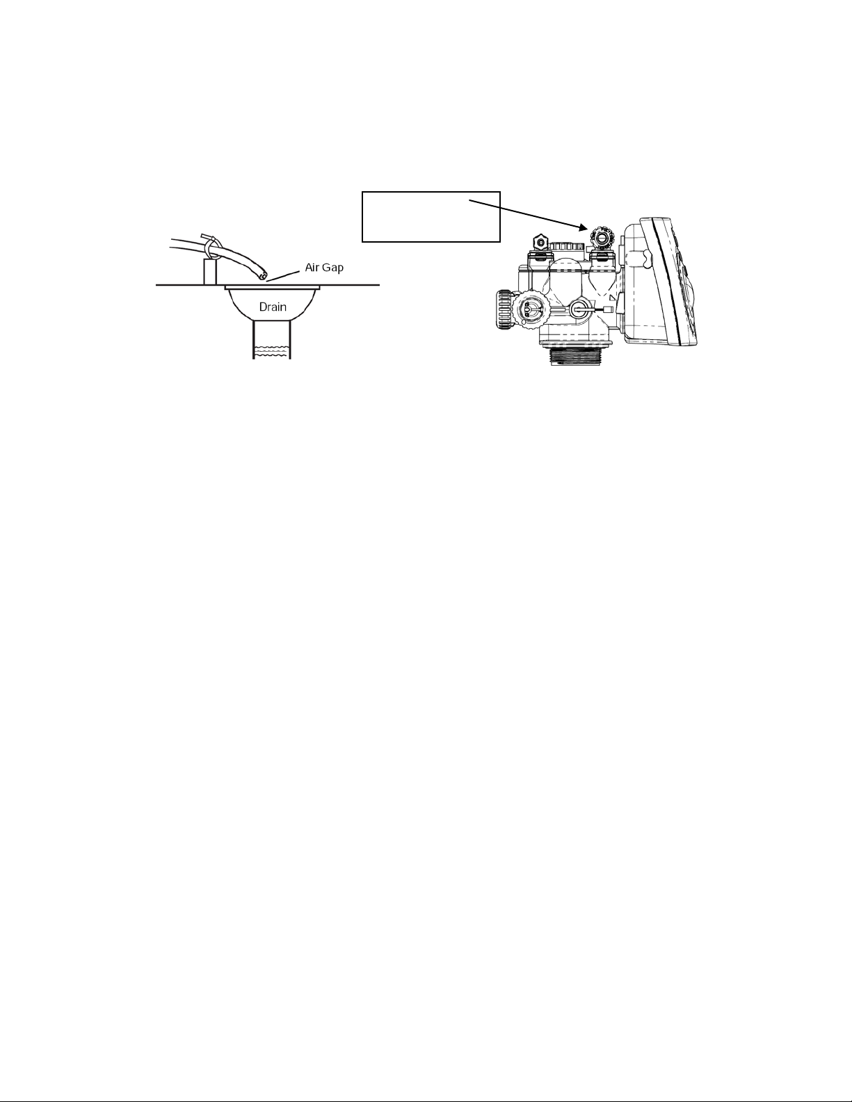
3. The drain line connection is 5/8 OD or ¾” npt and is located on the
top left of the valve as you face the timer. It is recommended you
Control Valve
Bypass Valve
Tail piece assembly
4
install a ¾” union on the drain line for servicing if not using 5/8 OD.
The drain line must be of adequate size to allow for full regeneration
flow.
•The control valve drain connection is 5/8 OD or 3/4"
npt.
•Never decrease the drain piping size to below drain
connection size.
•Maximum drain line length is 30 feet with proper slope
maintained the entire length.
•Maximum drain line height is 6 feet above the control
valve.
•The drain line must be piped to an open air gap (See
Figure above)
•Always follow local plumbing codes.
UNDER NO CIRCUMSTANCES SHOULD THERE BE A DIRECT
CONNECTION WITH SANITARY SEWAGE FACILITIES.
DRAIN LINE
CONNECTION
5
MASTER
Water Conditioning Corp.
Well Tank
NOTE: All Master Water Conditioners must be
installed after the well tank or water meter if its
public water supply.
Master Water
Conditioner
Brine tank
Air Gap Drain
Overflow
fitting to
floor drain
gravity
Untreated
TYPICAL PIPING LAYOUT FOR
MCA SERIES SOFTENER
Treated
6
Electrical Requirements:
Always follow all local electrical codes when installing our water
treatment equipment.
1. Provide an 115v/60Hz properly grounded dedicated electrical
Outlet. (It’s very important that the polarity be correct)
Avoid using outlets that are switch controlled.
2. Maximum amperage required is 5 amps.
3. Make sure the electrical service provides power 24 hours per day.
We recommend installing a surge protector to protect unit from
power surges, which are not covered by warranty.
Brine Tank:
1. The brine tank should be located directly beside the water softener
mineral tank.
2. Connect the 3/8" poly tubing to the 3/8” black elbow compression
fitting located on the top left side of the MCA control valve. Hand-
tighten.
See Figure Below.
The brine tank is equipped with a shutoff valve, the float height
was preset at the factory.
BRINE REFILL
CONNECTION
7
Filling Water Softener with Water:
1. Connect the MCA control valve transformer into the electrical outlet
provided.
2. Press and hold the Up and Down arrows simultaneously for three
seconds until the drive motor starts. When the drive motor stops, the
display will read “C1” backwash position.
3. Open the inlet ball valve a ¼ turn of its full open position to allow
water to enter the water softener mineral tank slowly. The water is
going to enter the tank from the bottom of the distributor pipe and
leave the tank from the top. This will slowly purge all the air from the
tank.
IF WATER ENTERS THE TANK TOO FAST, ALL THE CATION
RESIN WILL BE FLUSHED TO DRAIN DURING START UP.
4. When only water is running to the drain, open the inlet and outlet ball
valves fully.
5. Press the Up button to advance the control valve to the brine/rinse
position. The display will read “C2”.
6. Once the drive motor stops, press the Up button to advance the
control valve to the fast rinse position. The display will read “C4”.
The fast rinse position will rinse the softener tank.
7. The control valve will automatically advance to the brine refill position
where the brine tank will fill with the proper amount of water. The
display will read “C5”.
NOTE: THE TIMER WILL AUTOMATICALLY ADVANCE TO THE
SERVICE POSITION AND THE DISPLAY WILL READ TIME OF DAY.
8
MCA Control Valve Timer Settings:
Note: The control valve is set at the factory. You only need to set the
time of day and regeneration time if required, which is preset at 2 am.
Time of Day Setting
1) Press and hold the CLOCK button. The screen will display “Set
Time” and the hour will be blinking.
2) Press the UP or DOWN arrows to adjust the hour —check for
correct am or pm mode.
3) Press the CLOCK button.
4) Press the UP or DOWN arrows to adjust the minutes.
5) Press the CLOCK button.
Time of Regeneration Setting (the factory default is 2 AM)
Simultaneously press the CLOCK and the UP arrow for 3 seconds:
The screen will display “Set Time Regen” and the hour will be
blinking.
1) Use the UP or DOWN arrows to adjust hour.
2) Press the CLOCK button.
3) Press the UP or DOWN arrows to adjust the minutes.
4) Press the CLOCK button.
Regeneration Frequency Setting (the factory default is every 7 days)
The screen will display “Set Regen Day” and the days of
regeneration frequency will be blinking.
1) To change the number, use the UP or DOWN arrows.
2) Press the CLOCK button.
3) Set up is complete and the screen will now show the time.