10
Long term preservation (mothballing) of the plant (Page 1 of 2)
Description:
Prior to a longer period of shutdown, the Aquatec has to be preserved with chemical no. 3 (Biocide). After
mothballing, the plant can be shut down for 6 months, depending on the environmental conditions.
Attention!
Before preservation and longer downtime. The oil of the high-pressure pump must be
changed in order to remove any possibly existing condensation water from the oil. This
prevents corrosion of the bearin
s and surface of the crankshaft
Warning!
The conservation chemical no. 3 is a Biocide. Please consider the hazard notes on the
canisters. Working with chemicals, please wear protective glasses, breathing
protection and rubber
loves for
our own safet
.
Note!
If there any risk of frost, the entire pressure pipe with internal membrane in the pipe
should be dismounted (after preservation) and be stored frost-proof with closed hose
connections. The liquid present in the pressure pipe can be drained. Can the
membrane not be removed alternatively 20%- 50% glycerin in food quality can be
added as an antifreeze to the biocide at preservation (glycol is not permitted as
antifreeze). The plant has to be drained (filter housings, pumps, hoses). Remove filter
cartrid
es.
Instruction for mothballing.
Wa
nin
!
Make sure that you follow the following instructions carefully so that no cleaning
chemical gets into your fresh water tank.
Note!
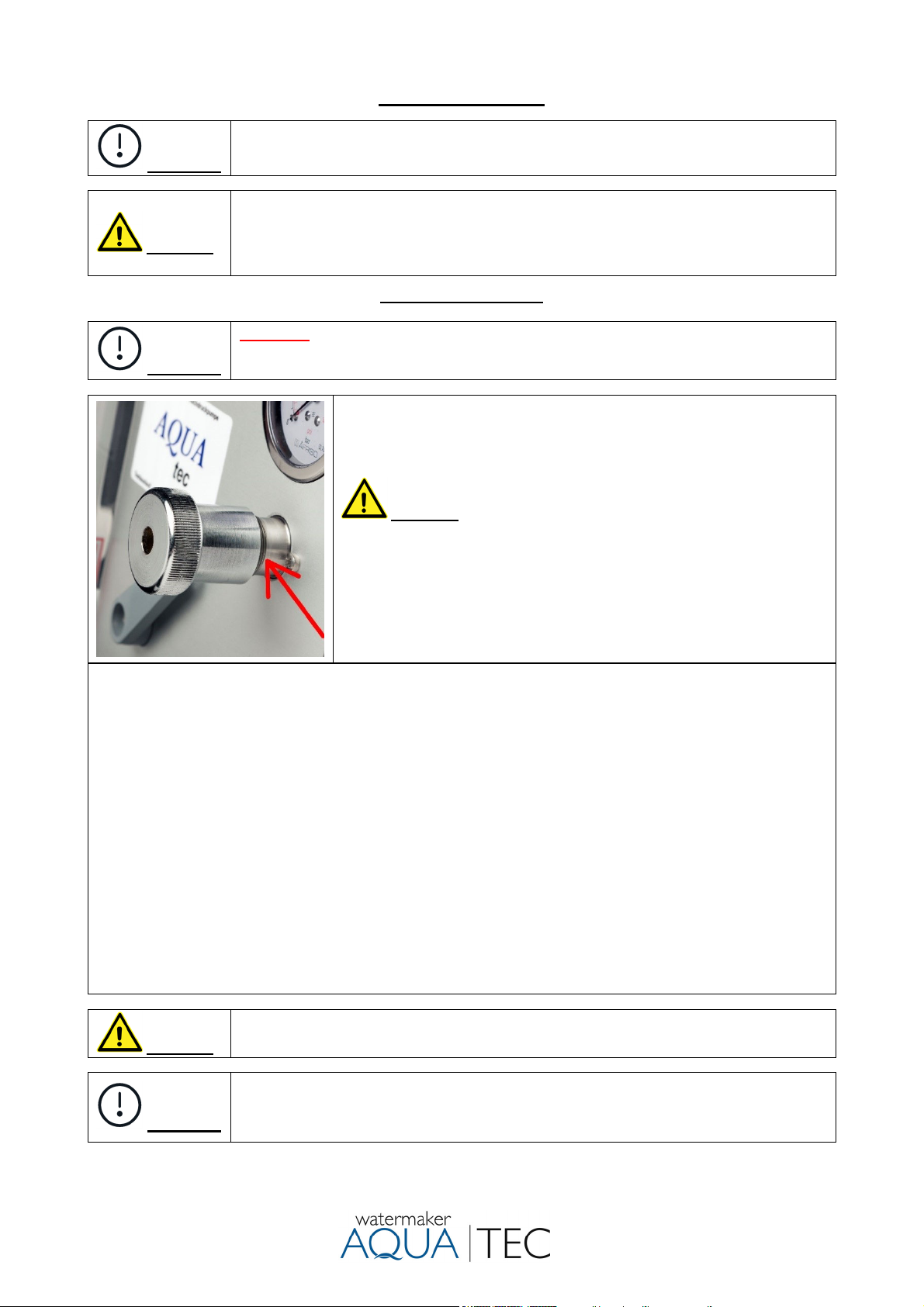
HP- Pump always pressureless!!! (Pressure control valve (5) open).
The only application with working pressure is the production of product water.
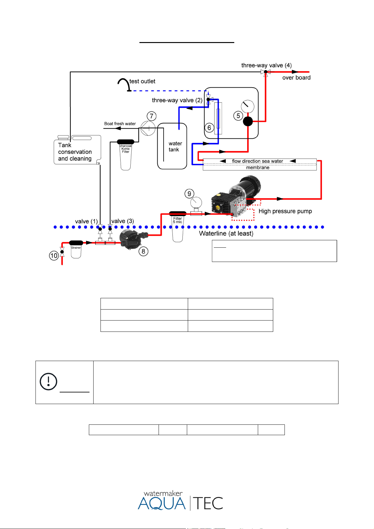
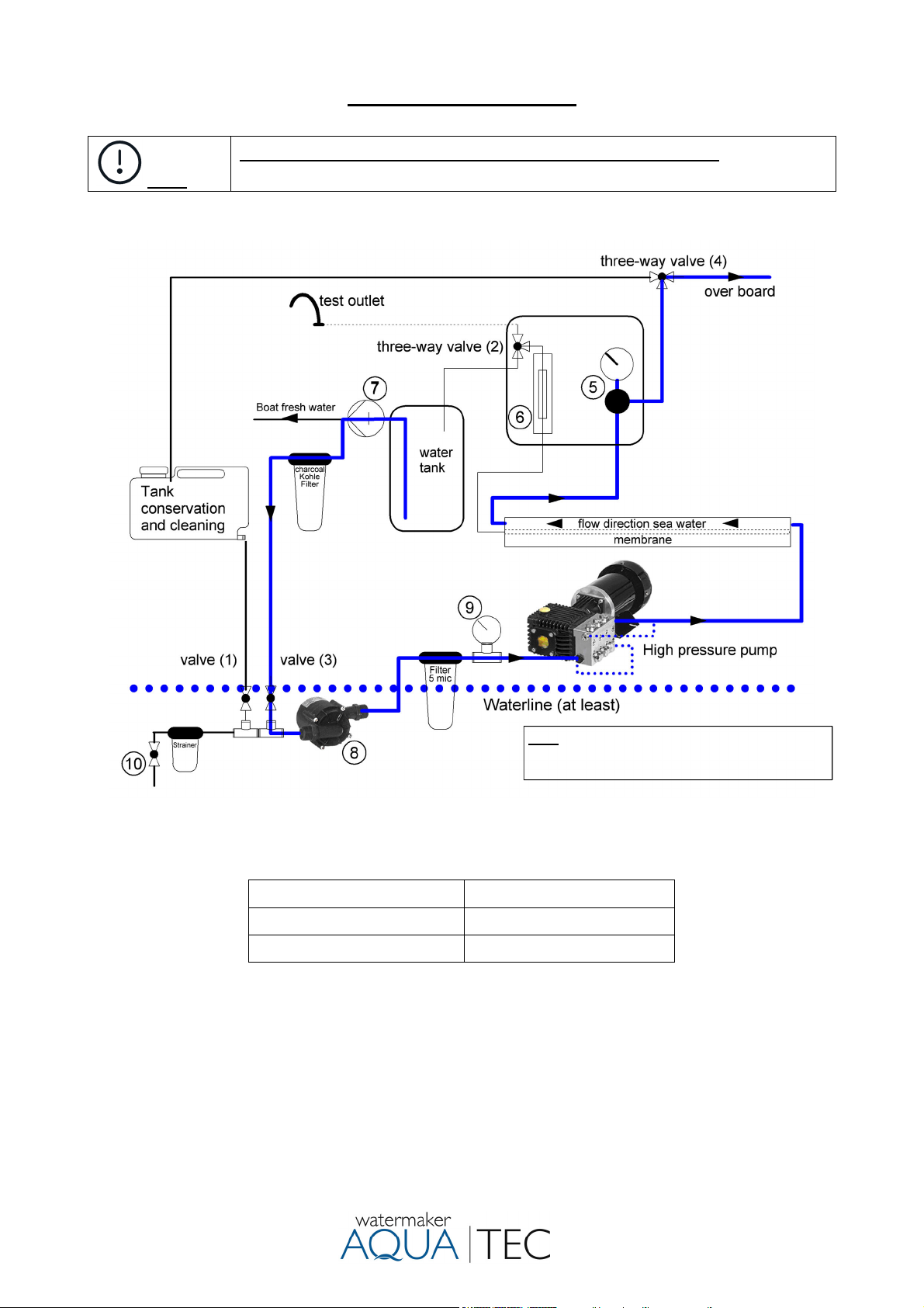
1) Close the sea water intake valve.
2) The pressure control valve must be open. Turn the product water three-way valve (no. 2) to position test-
outlet to avoid that chemicals get into the drinking water tank.
3) Rinse the system with fresh water as described in “Fresh water flushing”.
4) Turn the three-way valve (no. 4) according to the flow diagram “Long term preservation (mothballing) of
the plant”. Open valve (no.1).
5) Dissolve the stated amount of biocide (no. 3) completely in 10 litres of water and pour it into the tank for
conservation. (To avoid negative pressure, do not close the cap tightly) As a result of the water already
in the system, (each pre-filter= 1 litre, each membrane= 1.5 litres) together with these 10 litres, the result
will now be the maximum permitted concentration of 0.5% by weight. A level teaspoon corresponds
to 5 grams Biocide (Natriummetabisulfit).
6) Switch on the feed pump and the high-pressure pump. Let the Biocide circulate through the system for
about 2-3 minutes. Perform possibly exiting the test outlet liquid back into the preservative tank.
7) The Biocide in the tank can be discharged overboard after turning the three-way valve (no. 4). It should
be noted that the s
stem
ets no air. Switch pumps off.
Amount of biocide DD 500 max. 37 gr. Biocide
Note!
For preservation times of approx. 2 months, half of the chemical is sufficient.