Page - 4
Planning for Condensation
The heat pump can produce a large amount of condensation. The amount of water depends on air
temperature and humidity.
lInstall the heat pump with enough height to allow for water drainage.
lPlan for water drainage as needed.
Mounting Pad Requirements
lThe heat pump's base must be installed on a flat and level surface that completely supports the entire base.
lBuild the heat pump pad out of concrete or other code-approved material.
lConfirm the pad can support the weight of the heat pump.
lElevate the pad enough to allow for drainage.
lMake sure the pad is flat and level.
lHave the pad support the entire heat pump base in all directions.
lDo not install the heat pump on soil or grass.
lDo not allow the heat pump base to touch the building's foundation.
lDo not place the heat pump directly on a concrete floor. This can cause noise to be transmitted to an occupied
space. If necessary install vibration dampers between the heat pump base and floor.
lEquipment pad must meet all requirements of authorities having code-related jurisdiction.
Anchoring to Pad
lFollow all applicable local, state, and national requirements regarding wind load anchoring.
lThe shipping brackets used to secure the heat pump to the pallet are approved mounting (hurricane) brackets.
They should be used to anchor the heat pump to the pad.
lIf needed, contact Aquatherm to obtain anchoring kit information. Please have the heat pump model number and
serial number when requesting support.
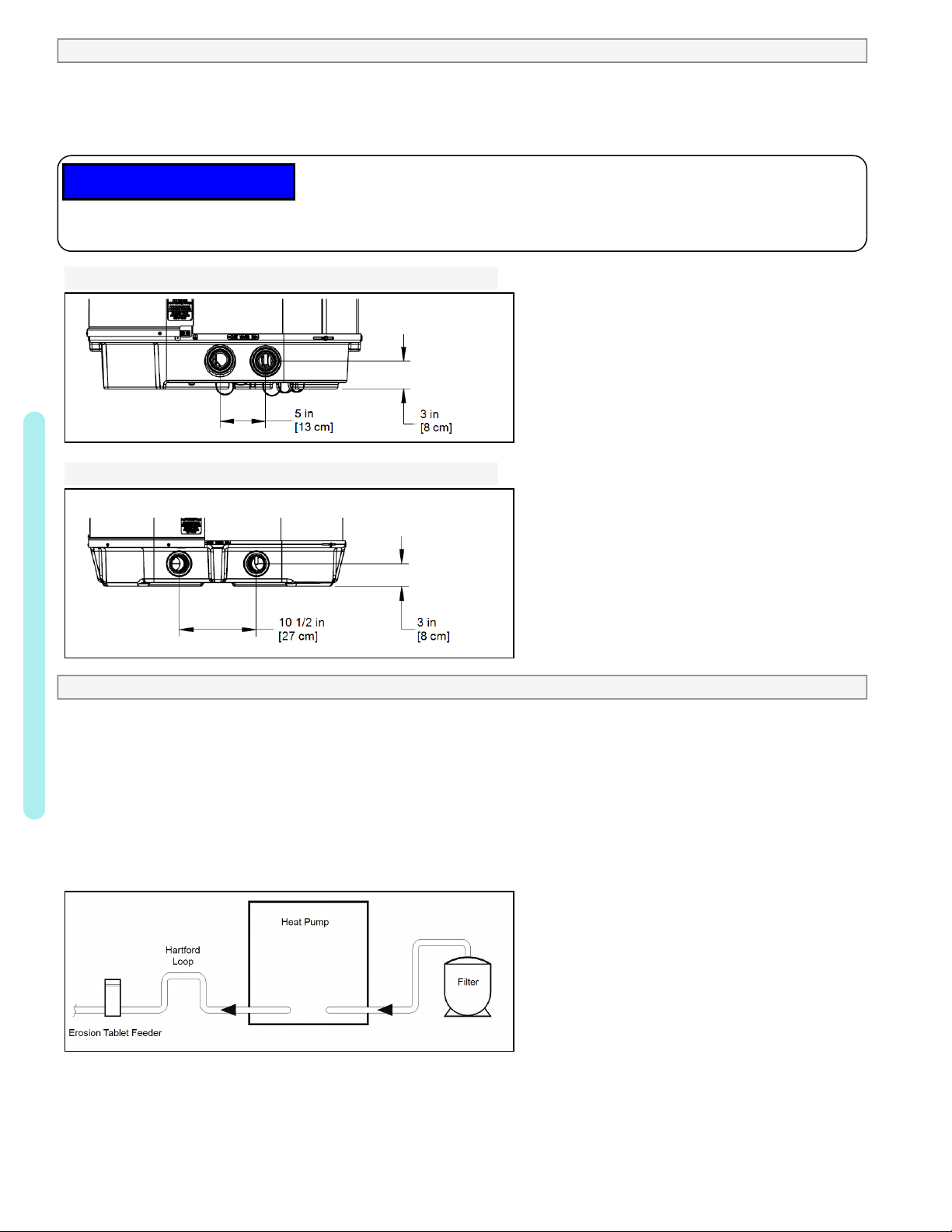
1.2 Plumbing
1.2.a Plumbing Requirements
lThe heat pump must receive water flow under worst-case conditions such as a fouled water filter.
lFailure to provide clean filtered water to the heat pump can void the product warranty.
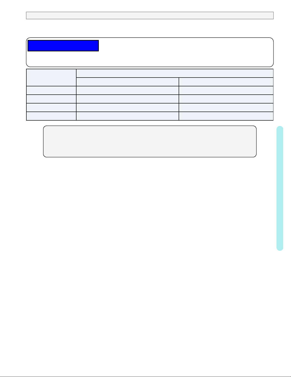
lWater flow exceeding maximum flow rates will negatively affect the total pool filtration performance and may
damage the heat pump. This will not be covered under the equipment warranty. See "Water Flow Rates" on
page6.
lInstall a bypass valve whenever water-flow may exceed the maximum rating.
lFor additional guidance testing water flow rates, please contact Aquatherm.
lA safety-enhancing "Over Temperature Alarm"kit is strongly recommended for all spa applications.
lFollow the basic plumbing diagrams as provided in the appendix of this manual. See "Appendix" on page12.
1.2.b Maintaining Ability to Winterize
Do not use glue on the threaded portion of the equipment’s unions. A glued-in-place union will prevent the
equipment from being properly winterized.
1 - Installation