Aquatic Access IGAT-180 AD User manual

In
Aquatic Access Inc.
Pool Lift Model IGAT-180 AD
Installation Guide
Instruction Manual
AquaticAccess.com
1921 Production Drive, Louisville, Kentucky 40299-2110 USA
800.325.5438 502.425.5817 Fax: 502.425.9607


Contact:
Aquatic Access Inc.
1921 Production Drive
Louisville, KY USA 40299-2110
Toll Free 800.325.5438 Phone 502.425.5817
Table of Contents
Installation. . . . . . . . . . . . . . . . . . . . . . . . . . . . . . . . . . . . . . . . . . . . . . . . . . .
Socket Placement . . . . . . . . . . . . . . . . . . . . . . . . . . . . . . . . . . . . . . . . . . .
Socket Installation . . . . . . . . . . . . . . . . . . . . . . . . . . . . . . . . . . . . . . . . . .
Lift Assembly . . . . . . . . . . . . . . . . . . . . . . . . . . . . . . . . . . . . . . . . . . . . . .
Water Connections . . . . . . . . . . . . . . . . . . . . . . . . . . . . . . . . . . . . . . . . . .
Water Pressure Chart . . . . . . . . . . . . . . . . . . . . . . . . . . . . . . . . . . . . . . .
Safety Procedures . . . . . . . . . . . . . . . . . . . . . . . . . . . . . . . . . . . . . . . . . . .
Sample Label to Indicate Location of Numbers Only . . . . . . . . . . . . .
Service and Maintenance . . . . . . . . . . . . . . . . . . . . . . . . . . . . . . . . . . . . . . .
Inspection of Lift . . . . . . . . . . . . . . . . . . . . . . . . . . . . . . . . . . . . . . . . . . . .
Disassemby of Lift and Replacement of Piston Seal . . . . . . . . . . . . . . .
Replacement of Piston and/or Top Guide . . . . . . . . . . . . . . . . . . . . . . . .
Replacement of Rub Block . . . . . . . . . . . . . . . . . . . . . . . . . . . . . . . . . . . .
Replacement of Seat Shell . . . . . . . . . . . . . . . . . . . . . . . . . . . . . . . . . . . .
Replacement of Valve Assembly . . . . . . . . . . . . . . . . . . . . . . . . . . . . . . . .
Replacement of Valve Stem . . . . . . . . . . . . . . . . . . . . . . . . . . . . . . . . . . .
Transporting the Lift . . . . . . . . . . . . . . . . . . . . . . . . . . . . . . . . . . . . . . . .
Troubleshooting . . . . . . . . . . . . . . . . . . . . . . . . . . . . . . . . . . . . . . . . . . . . . .
Addendum: Technical Specications .. . . . . . . . . . . . . . . . . . . . . . . . . . . . .
1
1
1
2
2
3
4
5
6
6
7
8
8
9
10
11
11
12
13
Visit Us Online at www.AquaticAccess.com

1
POOL LIFT MODEL IGAT-180 ABOVE-DECK
The customer and installer are responsible for ensuring the strength of the mounting for the pool
lift and for determining if grounding the unit is necessary. Installation directions must be followed
to meet advertised lifting capacities.
INSTALLATION
SOCKET PLACEMENT
The socket location is mutually agreed upon
by the customer or installer and Aquatic
Access.
Usually, the customer provides Aquatic
Access with a drawing showing the
measurements and conguration of the
deck, coping, gutter, and pool wall. This
allows our engineers to determine the best
location for the socket. A distance of
42" – 48" from the deck to pool oor is ideal
for installation.
The lift should normally be located at least 36" away from pool
corners and ladders that could interfere with the turn of the seat. The
socket should also not be placed directly on an expansion joint, but
at least 4" away from it. If unsure about the measurements,
congurations or structural integrity, have a local contractor verify
them.
If you have received the socket in advance of the lift without
instructions as to how far away from the pool edge to install the
socket, or if any questions remain, consult with the engineers at
Aquatic Access before installing the socket.
SOCKET INSTALLATION
Some states and localities require grounding of any metal object within ve feet of the pool edge,
but this is sometimes difcult in retrot versus new installations. Each socket has a grounding
lug on the bottom to connect to a grounding rod. Electrolysis (staining of the stainless steel) may
result if the lift is not properly grounded. Consult your local building codes for grounding
information.

The socket is located in the seat box and is attached under the seat.
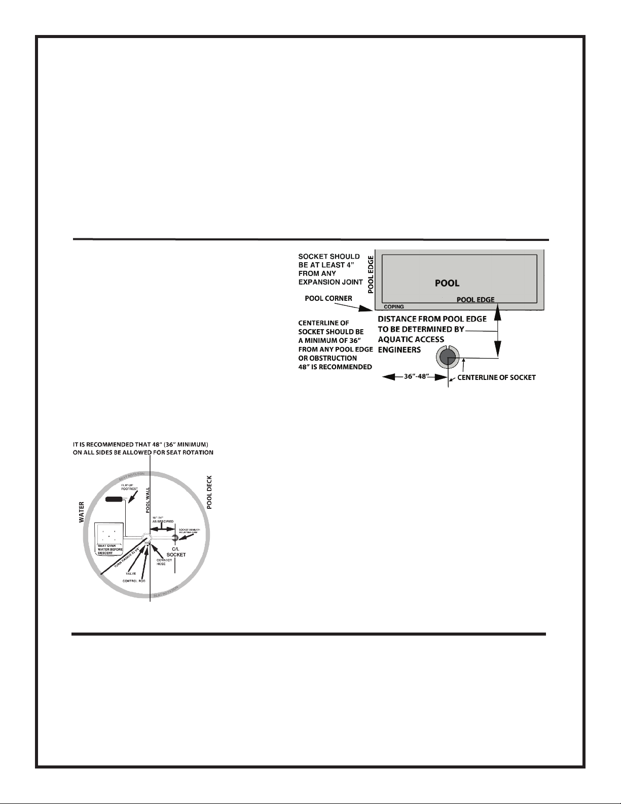
A 5" carbide core drill makes an excellent clean hole in solid concrete. The centerline of the
socket hole should be _____" from the pool wall or ______" from the edge of the deck. Drill
the hole at least 12"deep. Some customers have found it useful to insert a piece of pipe that is at
least 24" long full depth into the socket. Tape the top end of the socket to the pipe to prevent any
liquid cement from entering the top of the socket. This assures a clean socket interior when the
pipe is removed after the cement is hard. Pour a small amount of anchor cement into the bottom
of the hole. After placing the socket into the hole so that its top edge is ush with the surface of
the deck and the notch in the top of the socket is facing the pool, pour the anchor cement around
the socket. A spirit level should be held along the extension pipe to assure that the socket is
vertically plumb while the cement sets (about 15 minutes). Allow the cement to cure overnight
before proceeding.
LIFT ASSEMBLY
1. Insert lift into socket.
2. Attach seat assembly to cylinder assembly with the bolt provided. Adjust seat height by
choice of hole on piston rod frame. Tighten lock nut securely, making sure bolt has penetrated
nylon insert of lock nut. Two bolt threads should be visible past the nylon insert.
3. On the IGAT-180AD, which normally includes a footrest, rst unscrew the T-bolt under the
side of the seat, and then insert the top of the footrest tube into the holder. Slide in to desired
length and turn T-bolt handle clockwise to tighten.
4. If the optional headrest has been ordered, follow the same procedure as footrest to install the
headrest in the headrest bracket on the seat back.
5. Seat belts are installed by sliding the belts through the upper and/or lower slots cut into the
side edges of the seat.
WATER CONNECTIONS
The pool lift is operated by city/household water pressure, with no electricity needed. Our
system is designed for most efcient operation at 60-PSI static pressure or 55 PSI operating
(open ow) pressure to lift 350 lbs. Note that the pressure requirement for a faucet or hose
connection is approximately 10% higher to achieve the rated load.
If your static water pressure measurement is greater than 70 PSI, a reducer must be used between
the water sources and the lift or damage to the lift may result. Purchase a reducer at your local
plumbing supply store. Aquatic Access Inc. is not liable or responsible for damage caused by
excessive water pressure.
2

Most installations will operate
from a garden hose connected
to a convenient faucet.
However, on new deck
construction, a recessed water
connection with a shut-off
valve may be plumbed in and a
short appliance hose can serve
as a connection.
If a recessed water source is
installed, when you are
facing the pool, and the lift is
between you and the water, the
recessed water source should
be placed to the RIGHT side
of the socket.
Height requirements for a
standard IGAT-180 AD
installation are illustrated on
the right.
Weight Lifted at Open Flow Water Pressure
(Add approximately 10% for static water pressure)
Lifting capacity was tested at lift connection on a baseline unit with operating water pressure
while lifting (open ow pressure) and under ideal mounting conditions pursuant to installation
instructions. Static water pressure measurement will be approximately 10% higher.
3
PSI Bars Pounds Kilograms
28-30 PSI 1.93-2.06 Bars 150 68
41-45 PSI 2.83-3.10 Bars 250 113
55-65 PSI 3.79-4.48 Bars 350 159

Installation variable may also require a higher water pressure than listed. These may be the result
of the cylinder not being installed and maintained in a vertical position.
In true low water pressure situations, electric pumps are available to provide sufcient water
pressure for up to a 350 lb. lifting capacity.
SAFETY PROCEDURES
Your IGAT model swimming pool lift is not a toy, but a tool that enables a physically impaired
individual to access water activities. It is designed with safety as a primary concern, but normal
prudence is expected to be exercised by the user of our lift. With proper care and usage, your
IGAT swimming pool lift will serve many years. Here are a few tips for safe usage of your lift.
1. Never allow more than one person on the lift at a time.
2. Keep ngers, towels and loose clothing away from moving parts.
3. Do not hang towels or robes on lift at any time.
4. Do not allow people to climb on or hang from lift.
5. Do not allow playing or rough–housing on or around the lift.
6. Do not jump or dive from lift.
7. Turn water supply OFF when the lift is to be left unused for eight hours or longer.
8. Be certain swimmer is settled in the seat before operating lift.
9. Do not exceed weight and pressure limits.
10. Do not use lift during an electrical storm or high wind.
11. Always drain water from cylinder before exposing lift to temperatures below freezing.
12. Never use any sort of oil or petroleum-based product on the inside of the cylinder; it will
damage the piston and seal.
SAFETY TIP: Even when lift is operated by the seat occupant, we recommend
that another person be nearby in case of emergency.
4

5

SERVICE AND MAINTENANCE
INSPECTION OF LIFT
The lift should be inspected each day
before use. Check for hose damage,
loose connections, any corrosion or
damage to any parts of the lift
routinely before using the lift with
a swimmer.
Perform a more thorough inspection
of the lift every three months if the
unit is in use all year round:
1. Examine bolts for corrosion, or
wear. Check for wear on lanyard and
pull-pin as well as other parts.
Inspect unit more frequently if unit
is in highly corrosive atmosphere or
has high use such as at a public pool
or therapy center.
2. Check screws and hose clamps
periodically to make sure they are
tight. Replace any parts that are cor-
roded.
3. If the stainless has become
discolored from chlorine and other
chemicals in the pool, clean the lift
only with a soft cloth or Scotchbrite®
pad. After cleaning and rinsing apply
car wax and buff to help maintain a
bright appearance. Never use steel
wool to clean the lift. Prolonged
exposure to the elements may result
in some discoloration and crazing of
non-metallic components.
4. When the lift is installed in a wood deck check deck for signs of decay. Replace worn or
damaged decking as necessary. It is the responsibility of the owner to check the deck for
structural integrity.
6

DISASSEMBLY OF LIFT AND REPLACEMENT OF PISTON SEAL
1. Remove seat assembly from lift and disconnect water supply. Drain water from Lift.
2. Remove lift from socket.
3. Remove four bolts at top of lift.
4. Pull the piston rod assembly completely
out of cylinder. Be careful not to damage
seal.
5. Remove O-ring and then seal from
bottom of piston. Clean seal and inspect
for signs of cuts, abrasions or tears.
Replace seal if damaged. If original seal is
good reinstall on piston and then replace
O-ring. Make sure O-Ring is seated rmly
in groove.
6. Inspect cylinder for signs of dirt or debris. Formula 409® can be used to clean the inside of
the cylinder and seal. Wrap a soft bath towel around a broom handle and push it through the unit,
taking care not to scratch the inside of the cylinder wall. Rinse out the cylinder with clean water.
It is easier to seat the seal when the inside surface of the cylinder is damp with either Formula
409® or water. Never use any oil or petroleum-based product inside the cylinder, as it will
damage the piston and seal.
7. Carefully slide piston rod assembly back into cylinder. Take care not to damage seal while
replacing piston rod assembly into cylinder.
8. Push piston rod assembly in until piston rests on the bottom of the lift.
9. Align holes in top cylinder bushing with holes at top of main cylinder. Install bolts and attach
pull-pin, but do not tighten bolts completely yet. (See illustration)
10. Install lift into socket. Connect water supply. Purge air as normal.
11. When lift reaches top position tighten four bolts securely. Do not over tighten bolts to avoid
stripping the threads in the plastic.
12. Attach seat assembly.
7

REPLACEMENT OF THE PISTON AND/OR THE TOP GUIDE
1. Follow directions for Disassembly of Lift and Replacement of Piston Seal, steps 1-3.
2. Remove piston from end of piston rod using a rubber or plastic mallet. Go to step 5 of this
section if you are only replacing the piston and not replacing the top guide.
3. Remove old top cylinder bushing and replace with new top cylinder bushing. Note that the
threaded holes in the top bushing are off center. The holes need to be positioned so that they are
towards the top of the lift. (See illustration)
4. Install spacer on piston rod. Clean spacer if it is dirty.
5. Install piston on end of piston rod using a rubber or plastic mallet. Hit bottom of piston until
piston is rmly seated. Piston should be able to rotate freely after being attached. (See detail in
illustration
6. Go to step 6 of Disassembly of Lift and Replacement of Piston Seal and continue through step
11.
REPLACEMENT OF RUB BLOCK
1. Follow directions for Disassembly of Lift and Replacing Piston Seal.
2. Insert a small block of wood or plastic between piston rod and piston frame to spread apart.
(See illustration)
3. Remove rub block. Install new rub block. (See illustration for orientation of rub block.)
4. Go to step 6 of Disassembly of Lift and Replacement of Piston Seal and continue through step
11.
8

Orientation of Rub Block for (A) IGAT-180 Above Deck and IGAT-180/135 Above Deck, (B)
IGAT-180 Above Deck Opposite Turn and IGAT 180/135 Opposite Turn, (C) IGAT-90 Above
Deck, and (D) IGAT-90 Above Deck Opposite Turn.
REPLACEMENT OF SEAT SHELL
1. Remove footrest and head rest from chair
if applicable and remove chair from lift.
2. To replace seat shell unscrew nuts which
attach to seat frame and arms to shell.
3. Attach seat frame to new seat shell and
tighten bolts.
4. Attach arms to new seat. Replace nuts and
bolts. Lower hole(s) on seat will have to be
drilled by customer using a 1/4" drill bit.
5. Attach seat to lift and install footrest and head rest.
9
Detail Showing Rub Block between the Piston Rod and the Piston Frame

REPLACEMENT OF VALVE ASSEMBLY
1. Disconnect water supply.
2. Remove hoses from the valve assembly and unscrew brass nut that secures the valve bracket.
(See illustration)
3. Install new valve by reversing process above.
REMINDER
Remember to mail in your warranty card to Aquatic Access Inc.
Make a note of the serial number and date of purchase below. This information will be needed
should you wish to contact Aquatic Access. You will nd the serial number on the label on the
cylinder portion of your lift.
Serial Number ________________________________________________________
Purchased from ________________________________________________________
Date of Purchase _______________________________________________________
Notes:
10

REPLACEMENT OF VALVE STEM
1. Disconnect the water supply.
2.Unscrew the brass nut that secures the valve to the valve bracket so that the valve drops down
where it can be accessed. Set the nut aside for reassembly. Hold the valve so the tab that mates
with the control rod
3. Apply lithium grease (provided with the replacement valve stem) to the end of the new valve
stem and replace stem in the valve assembly, matching alignment of the tab. Make certain that
the square shaft is completely seated in the square hole. Reinsert the valve assembly into the
valve bracket and secure with the brass nut.
4. Reconnect the water supply.
TRANSPORTING THE LIFT
1. Lower the seat on your unit to the down position.
2. Turn control knob to OFF.
3. Turn off the water and disconnect the water line from the unit.
4. Lift the unit out of the socket and carry away.
5. Place socket cover over the socket in the deck.
11

TROUBLESHOOTING
Symptom Cause Remedy
Seat bounces on descent Air in the cylinder Purge air out by running the
lift up and down two or three
times. See operating label.
Air in Cylinder Every Day Air entering hose or cylinder if
seat is left in the down position
and the water is shut off.
Purge air out by running the
lift up and down two or three
times. See operating label
Lift rises slower than normal Low Water Pressure
(Heavier than usual swimmer on
lift; defective hose, dirt in valve
could also cause)
Lift kept under pressure.
None. Fluctuations in city water
pressure are not unusual.
(Replace defective part or clean
valve)
Turn off water each night.
Waters squirts from top of
cylinder
Large amounts of water are
getting past the seal.
Often this corrects itself. If not,
then clean or replace the seal.
White, gray or brown chalky
deposit.
High pH, high total alkalinity,
high calcium content (hard)
water
Clean unit with soft cloth or
Scotchbrite® pad, apply car wax
to protect finish.
Corrosion of Metal Parts Low pH, Low total alkalinity, low
calcium content (soft) water.
Clean unit with soft cloth or
Scotchbrite®pad, apply car wax
to protect finish.
Water leakage from top of valve Seal around valve stem
defective
Replace defective part.
Chair doesn’t come up all the
way
Deposits or dirt in valve,
malfunction of valve
Clean or replace valve.
Electrolysis Improper grounding of unit Add a ground to unit.
-
12

ADDENDUM: TECHNICAL SPECIFICATIONS: Model IGAT-180 AD
United States Patent #5,465,433
LIFTING CAPACITY 350 lb. @ 55-65 PSI / 159 kg@ 3.8-4.5 Bars
operating pressure (10% higher if static
pressure)
STATIC LOAD TEST 525 lb. / 238 kg
OPERATION Standard city water pressure will generally
provide plenty of pressure for normal
operation. A pump can be used to raise
pressure if necessary. However, do not use
a high volume pump. The correct pump
would provide three to five gallons (US)
per minute at 40 PSI (2.8 Bar) to 70-PSI (4.8
Bar) maximum pressure.
ROTATION Automatic 180° Turn
MATERIALS 304 & 316L Stainless, UHMW plastic, Brass
and Rubber
OVERALL SIZE HEIGHT 110”(2790 mm)
RANGE OF MOTION Standard lift provides 44”(1124 mm)
vertical travel. Custom travel can be
provided.
PORTABILITY Lift can be removed with no tools and
stored out of sight. Lift drops into socket
for use.
WARRANTY The IGAT pool lift carries a 6 year Limited
Warranty on all structural components
and a 2 year Limited Warranty on the
valve, plastic and rubber components.
Aquatic Access Model IGAT-180AD Instructions Revised 2/13/15
13
Other manuals for IGAT-180 AD
1
Table of contents
Other Aquatic Access Lifting System manuals
Popular Lifting System manuals by other brands

Harmar Mobility
Harmar Mobility AL215 Axis I Installation & owner's manual

morse
morse 510M Operator's manual

Rotary
Rotary 100 Series Operation and maintenance manual

POP UP
POP UP IQ LIFT PRO 7 ACTIVE Use and maintenance manual

Snorkel
Snorkel TM12 Series Service and parts manual

AUTOPSTENHOJ
AUTOPSTENHOJ Masterlift 2.30 installation instructions