Aquatic Access IGMT User manual

Aquatic Access Inc.
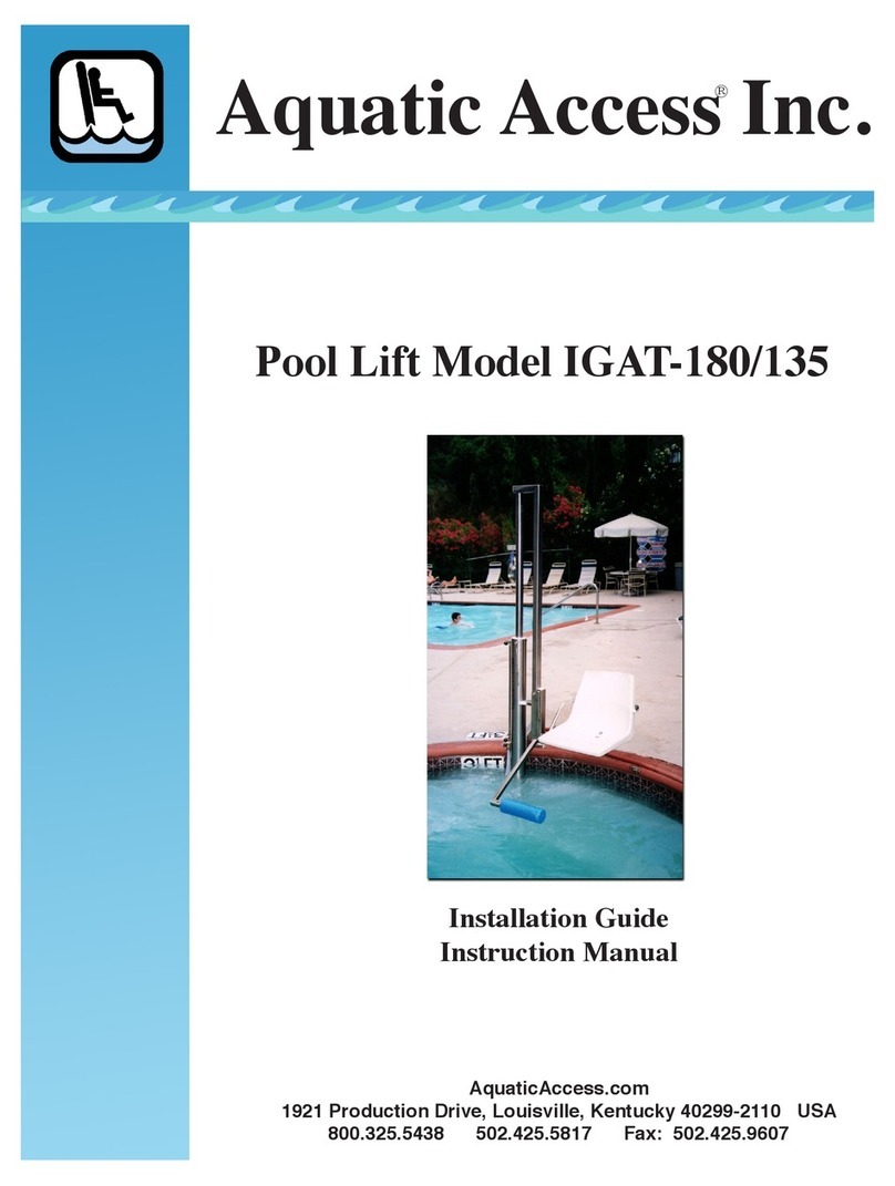
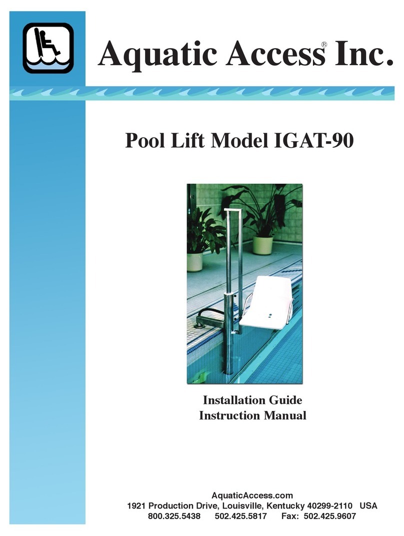
Pool Lift Model IGMT
Installation Guide
Instruction Manual
®
AquaticAccess.com
1921 Production Drive, Louisville, Kentucky 40299-2110 USA
800.325.5438 502.425.5817 Fax: 502.425.9607


Contact:
Aquatic Access Inc.
1921 Production Drive
Louisville, KY USA 40299-2110
Toll Free 800.325.5438 Phone 502.425.5187
Table of Contents
Installation. . . . . . . . . . . . . . . . . . . . . . . . . . . . . . . . . . . . . . . . . . . . . . . .
Placement of Socket. . . . . . . . . . . . . . . . . . . . . . . . . . . . . . . . . . . . . . . . . . .
Socket Installation for Concrete Decks . . . . . . . . . . . . . . . . . . . . . . . . . . .
Alternative Installations . . . . . . . . . . . . . . . . . . . . . . . . . . . . . . . . . . . . . . .
Assembly of Lift . . . . . . . . . . . . . . . . . . . . . . . . . . . . . . . . . . . . . . . . . . . . . .
Water Connection . . . . . . . . . . . . . . . . . . . . . . . . . . . . . . . . . . . . . . . . . . . .
Attach Seat . . . . . . . . . . . . . . . . . . . . . . . . . . . . . . . . . . . . . . . . . . . . . . . . . .
Operation of Lift . . . . . . . . . . . . . . . . . . . . . . . . . . . . . . . . . . . . . . . . . . . .
Service and Maintenance . . . . . . . . . . . . . . . . . . . . . . . . . . . . . . . .
Routine Inspection . . . . . . . . . . . . . . . . . . . . . . . . . . . . . . . . . . . . . . . . . . . .
Disassembly of Lift . . . . . . . . . . . . . . . . . . . . . . . . . . . . . . . . . . . . . . . . . . .
Determining the Cause of a Leak . . . . . . . . . . . . . . . . . . . . . . . . . . . . . . . .
Cleaning the Inside of the Cylinder . . . . . . . . . . . . . . . . . . . . . . . . . . . . . .
To Reassemble the Unit . . . . . . . . . . . . . . . . . . . . . . . . . . . . . . . . . . . . . . . .
Before Using the Lift Again . . . . . . . . . . . . . . . . . . . . . . . . . . . . . . . . . . . .
Safety Procedures . . . . . . . . . . . . . . . . . . . . . . . . . . . . . . . . . . . . . . . .
Troubleshooting . . . . . . . . . . . . . . . . . . . . . . . . . . . . . . . . . . . . . . . . . . . . . .
Addendum: Technical Specications of Above-Ground Pool Lifts. . . . .
Visit us online at AquaticAccess.com!
1
1
1
1
14
3
4
4
5
6
8
8
8
9
13
5
5
11


POOL LIFT MODEL IGMT
INSTALLATION
PLACEMENT OF SOCKET
Install the socket for the IGMT pool lift at least
3’ from any pool corner to insure that there is
enough room for the seat’s rotation and for the
swimmer’s feet to clear the edge of the pool.
Locate the socket at least 12” but less than 18”
from the edge of the pool.
SOCKET INSTALLATION IN CONCRETE
The IGMT socket is constructed of 2 1/2”
Sch. 40 stainless steel pipe, 6 1/2” long with
a welded-in base and a short grounding stud. A plastic liner inside the pipe ensures an easy
rotation for the lift.
Using a 4” carbide core drill
(provided by the customer), drill
a hole in the concrete decking and
clear to a depth of 8”. Fill the hole
around the socket with a good
grade of hydraulic cement. Take
care to prevent cement from falling
inside. Place the socket in the hole
with its top edge ush with the
surface of the deck. Using a level
held inside the socket, determine that the socket is absolutely vertical. If the socket for the lift is
not vertical, the installed lift will slowly
swing to the low side. Allow the cement
to cure overnight before installing the
pool lift.
ALTERNATIVE INSTALLATIONS
In some pool environments, a socket
plate is a better installation choice. When
the IGMT pool lift is to be installed on
1

a wooden deck or in a concrete deck with a void
beneath, a socket plate installation may be
necessary. If a socket plate is to be installed on a
concrete deck with no void beneath, anchor bolts
are used.
For installations where there is access below
the deck, stainless steel bolts are installed
through the deck and pre-drilled stainless steel
strongbacks, then secured with nuts and bolts.
These stainless steel supports are available from
Aquatic Access.
Using the socket plate as a guide, drill holes in
the deck for the bolts and socket to pass through.
If using strongback supports
underneath, use the socket plate as
a guide to position holes in them as
well.
Align the holes in the supports
underneath with the socket plate
above and insert bolts. Place washers
and nuts on bolt and tighten securely.
For installations where there is a
concrete deck with a void beneath,
1/2” anchor bolts are used to
secure the anchor plate in instances
where there is no access to the
void. For installations where there
is an accessible void beneath a concrete deck, a socket plate is used with strongbacks in a
conguration similar to that for wooden decks.
ASSEMBLY OF LIFT
Your IGMT pool lift has been assembled and tested in the factory before shipping. All parts are
included in your shipment. Study the illustration of the lift in order to become familiar with its
parts and their names. A reinforced garden hose connected to a nearby water source is needed
to supply the lifting power. In cases of new construction, a water connection can be plumbed in
specically for the lift.
The standard IGMT pool lift is shipped in three cartons.
2

Carton #1: One long carton contains the lift cylinder, the valve, the socket, the socket cover, and
possibly any accessories you ordered.
Carton #2: The square box contains the seat assembly, and possibly any accessories.
Carton #3: The mast is contained in the third package.
After you have installed the socket and allowed the cement to cure overnight, insert the mast
into the socket and check that it rotates freely.
Remove the bolt from the rectangular tubing on the cylinder assembly. Also remove the turn
handle. Pick up the cylinder assembly and insert the rectangular tubing into the mast.
3

SAFETY ITEM: It is imperative that the top mounting bolt extend through both cylinder walls
and through the square key tube.The lift may malfunction if the square key is not properly
engaged and injury could result.
Place turning handle in position and reinsert the 1/2” bolt through all three components. Place
locknut on end of bolt and tighten to snug.
WATER CONNECTION
Connect the water hose to the valve
and turn on the water supply. Do
not leave the water turned on when
the lift is not in frequent use.
Your IGMT pool lift operates using
normal household water pressures of
55-65 PSI. No electricity is used.
With sufcient water pressure and
proper installation, the IGMT will
lift a 300 lb. individual. If your
water pressure exceeds 70 PSI,
a reducer is necessary to prevent
damage to the lift. Although 55-65
PSI is required to lift the rated load,
less weight can be lifted wiht lower
pressures.
In low pressure situations, a pump can be added to boost pressure. If a pump is used, do not
use water from the swimming pool to power the lift. Chemicals from the pool water may
damage the internal components of the lift. Follow the pump manufacturer’s instructions and
consult local building codes if you are installing a pump that exceeds 45 PSI. Never allow the
pump’s pressure to exceed 70 PSI. Excessive pressure can damage the lift.
Some customers prefer to install a recessed water connection specically for the lift. Place water
connection so that it doesn’t interfere with the user’s feet on rotation.
ATTACH SEAT
Turn the water on. Operate the control so that the seat tube/piston rod contracts into the cylinder.
Check for any leaks. If necessary, tighten valve. Rotate the seat to a position over the deck and
attach the seat with provided bolt. Secure with a lock nut and tighten snug.
4

OPERATION OF THE LIFT
Before operating the lift for the rst time each
day, turn on the water and run the lift up and
completely down two or three times to purge air
from the system. Always perform this operation
before anyone is seated on the lift. Once all air
has been purged from the system, raise the seat
to the up position.
Note: Purge the air from the lift every day. Air
in the system may cause the seat to drop several
inches suddenly. Make sure that the air has been
purged from the system before allowing anyone
to use the lift.
If your unit has been tted with the anti-rotation
lock option, insert the T-handle lock pin through
the 1”x 2” tubing at the deck transfer position.
This will prevent the lift from accidentally rotating while loading or unloading a person from the
lift. The only installation required for the locking mechanism is a 3/4” diameter hole aligned
with the T-handle lock in the desired stationary position.
Once the person is seated rotate the seat until it is over the water and lower the seat slowly by
opening the valve a little at a time. Speed, both up and down, can be controlled by the amount of
valve opening.
When exiting the pool, position the person in the seat. When the occupant is ready to go, turn
the valve to engage the water pressure and raise the seat. Rotate the seat over the deck and lock
in position to transfer.
SERVICE AND MAINTENANCE
ROUTINE INSPECTION
1. It is recommended that the unit be inspected periodically for damaged parts or excessive
wear.
2. Check the screws, nuts, bolts, and hose clamps to be sure all are snug. Clean any parts that
show signs of corrosion and replace any worn or damaged parts.
3. If the stainless steel has become discolored from chemical additives in the pool water or from
a corrosive atmosphere, it can be cleaned using a soft Scotchbrite® pad and a general purpose
cleaner such as Formula 409® or Fantastic®. Never use steel wool pads to clean the lift. After
5

cleaning with the pad, apply a good quality car wax to maintain its bright appearance.
4. If the lift is installed on a wooden deck, check the deck for any signs of decay. Replace any
worn or damaged decking.
DISASSEMBLY OF LIFT
TOOLS REQUIRED:
• two 3/4” (or adjustable) wrenches for top mounting bolt
• an adjustable wrench for removing valve
• 7/16” wrench for 4 bolts at bottom
• 3/16” Allen wrench for piston’s socket cap bolts
• a clean work surface
1. Turn off water and disconnect hose.
2. Remove nut and bolt from the seat bracket and remove seat assembly.
3. Rotate the cylinder over the water and extend the piston rod completely.
This will expel most of the water from inside cylinder.
4. Pull the piston rod back into cylinder by hand. Rotate the cylinder back over the deck
and let the piston rod rest on the deck. (You can keep the piston rod in the cylinder with
a bungee cord if you prefer.)
5. Remove the nut and bolt from the telescoping mounting arm members. Grasp the
cylinder with both hands and separate the cylinder from the mounting arm support.
6. Position the cylinder on a CLEAN table, bench, or oor. Study the drawings and parts
of the lift to understand the position of the parts. Notice that the seat bracket holes at the
bottom of the piston rod are parallel to the 1/2” top mounting bolt at the top of the cylin-
der. Use an adjustable wrench to unscrew the valve and remove it.
6

7. Remove the 1/2” top mounting bolt at the top of the cylinder and slide out the square
key tube. Put a nger against the white piston to prevent its sliding out with the square
key tube. If it does slide out, simply slide it back inside, being careful not to damage the
black seal.
8. Remove the four bolts at the bottom of the cylinder. Pull the piston rod assembly
out of the bottom of the cylinder. (Be certain that the valve has been removed (Step 6.)
before pulling the piston rod assembly out of the cylinder.) Be prepared for some water to
spill out as the bottom guide and seal exit. Sometimes the white bottom guide at the
bottom of the piston rod and the white piston attached to the top of the piston rod may
have swelled slightly (if they have been subject to high water pressure for a long time)
and as a result it will be difcult to get them out of the bottom of the cylinder. If this
happens, pull the piston rod out as far as it will go, then pull quickly several times, forc-
ing the white spacer tube to act as a hammer on the bottom guide until it exits. Slip the
bottom guide and seal off the piston rod, and continue to pull. If the piston gets stuck in
the bottom of the cylinder, push the piston rod back into the cylinder and remove it (with
the piston, seal, and spacer tube still attached) through the top of the cylinder.
9. Place the piston rod assembly on a CLEAN surface as dirt and debris will adversely
affect the lift’s performance. Handle the piston rod carefully. Any scratches on the piston
rod’s surface can cause a leak.
10. If the piston is to be replaced, use a 3/16” Allen wrench to unscrew the 4 socket cap
bolts in sides of the piston. It isn’t necessary to totally remove the bolts from the piston.
Put your ngers inside the top of the piston rod to feel when the bolts disengage from the
piston rod. Then remove the piston and seal from the top of the piston rod. If you don’t
have a 3/16” Allen wrench, you may carefully slide the top seal off the bottom of the pis-
ton rod while leaving the piston attached. If piston is not to be replaced, skip to step #
11. Inspect both top and bottom seals for any tears or cuts by bending the seal to stretch
the inner and outer lips. The seal should be soft and rubbery, not hard and stiff. Clean
the seals with a damp cloth and lightly clean the edges with a Scotchbrite® plastic pad.
Do not use steel wool or other abrasives on this or any other part of your lift. If the
seals are not damaged, place the top one back on the piston in the same manner it was
removed, tting it into the groove on the underside of the white piston with the open side
down.
If the seals are not damaged, place the top one back on the piston in the same manner it
was removed, tting it into the groove on the underside of the white piston with the open
side down.
7

Dirt or debris from the water or hard water deposits lodged between the inner cylinder
wall and the seal are the causes of most leaks. A very small particle which may not be
noticeable can still cause a signicant leak. Often simply cleaning the seal will solve a
leak problem.
12. Clean the inside of the cylinder by spraying with an all-purpose cleaner (Formula
409®or Fantastic®). Wrap a soft bath towel around a broom handle and push it through,
taking care not to scratch the inside cylinder wall.
DETERMINING THE CAUSE OF A LEAK
Most leaks are caused by some sort of dirt or debris from the water getting into the cylinder
and lodging between the seal and the cylinder wall. A very small particle can cause a signicant
leak. Often nothing is found since very small particles may not be noticeable at all. Thoroughly
clean the parts, seals, and interior of the cylinder wall and reassemble the lift. Often the leak
disappears after this simple procedure. Some leaks are caused by a seal developing a split,
by hard water deposits on the seal of the inside cylinder wall, or simply by age or wear.
Replacement seals are always available from Aquatic Access.
CLEANING OF THE INSIDE OF THE CYLINDER
To clean the inside of the cylinder, spray the inside with an all-purpose cleaner (Formula 409®
or Fantastic®). Wrap a soft bath towel around a broom handle and push it through the unit,
taking care not to scratch the inside of the cylinder wall. Never use any oil or petroleum-
based product inside the cylinder, as it will damage the piston and seals.
TO REASSEMBLE THE UNIT
1. Attach piston with four socket cap bolts and 3/16” Allen wrench. Make sure that
bolts go through piston rod by feeling the threads protrude inside piston rod with your
ngers .Tighten snugly but do not over-tighten or the threads in the plastic piston could
strip.
2. Slip top seal (with open side facing down) onto top of piston rod about 5” from top.
3. Slip the top seal into the groove at the bottom of the piston, tting it into the groove
on the underside of the white piston with the open side down.
4. If you have removed the piston rod and piston through the top of the cylinder, it will
have to go back in through the top of the cylinder. First, put the white spacer tube on the
bottom of the piston rod to help protect the cylinder wall from being scratched by the
8

piston rod while it is being inserted. While holding horizontally, insert the bottom of the
piston rod through the top of the cylinder, taking special care to gently insert the outer lip
of the top seal so that it will not be cut or torn on the top of the piston rod. Insert so that
the white piston is at least 6” from the top of the cylinder. It is easier to seat the seal when
the inside surface of the cylinder is damp with either Formula 409® or water. Never use
any oil or petroleum-based product inside the cylinder, as it will damage the piston and
seals.
5. Place the bottom seal in the groove of the bottom guide.
6. Slide the bottom guide with seal onto the bottom of the piston rod with the open side
of the seal facing up.
7. Slide the seal and guide into the cylinder, being careful to line up the four holes in the
guide with the holes at the bottom of the cylinder. If you push the guide too far into the
cylinder, pull out the piston rod until the spacer tube inside forces the guide back out the
bottom until the holes line up again.
8. Replace the four bolts through the bottom of the cylinder into the bottom guide. Tight-
en bolts evenly and snugly, but do not over-tighten to avoid stripping threads.
9. Once the piston rod assembly is installed, rotate it so the seat bracket holes at the bot-
tom of the piston are parallel to the 1/2”top mounting bolt holes at the top of the cylinder.
10. Slide the square key tube into the piston through the top
of the cylinder so that the holes at the top end of the square
key tube align with the top mounting bolt holes.
11. Insert the top mounting bolt through the cylinder wall,
the square key tube holes, and through the other cylinder
wall. Make certain that the seat bracket holes at the bottom
of the cylinder are still parallel to the top mounting bolt.
BEFORE USING THE LIFT AGAIN
Operate the lift to about one-fourth of its travel, and then lower completely. Repeat until a steady
stream of water ows from the discharge hose, signaling that all air has been purged from the
system. Air trapped in the cylinder will cause the motion of the seat’s up and down travel to jerk
and sometimes will cause a sudden drop of the last few inches in the seat’s downward travel.
Whenever you turn off the water supply, an air pocket will form inside the hose and you will
need to bleed the air out of the system again after the water supply is turned on. In a situation
where the lift is used frequently, you may wish to leave the water supply on all of the time
during normal use hours to eliminate the need to purge the system of air each time you use the
9

lift. After normal use hours, turn off the water and lower the lift slightly to relieve the pressure
on the piston and seals.
If you have any questions or concerns regarding your IGMT Pool Lift, please call Aquatic
Remember to send in your warranty card to Aquatic Access, 1921 Production Drive, Louisville,
KY 40299-2110. If it becomes necessary to replace any part in your unit, we need to know its
serial number and date of purchase. Take a moment to note this information below should you
ever need to call.
Aquatic Access Model IGMT Serial Number _______________________________________
Date of Purchase ___________________________Purchased From ____________________
NOTES:
10

SAFETY PROCEDURES
Your IGMT model swimming pool lift is not a toy, but a tool that enables a physically challenged
individual to access water activities. It is designed with safety as a primary concern, but exercise
prudence when using the lift. With proper care and usage, your IGMT swimming pool lift will
serve many years. Here are a few tips for safe usage of your lift.
Never allow more than one person on the lift at a time.
Keep fingers, towels and loose clothing away from moving parts.
Do not hang towels or robes on lift at any time.
Do not allow people to climb on or hang from lift.
Do not allow playing or rough–housing on or around the lift.
Do not jump or dive from lift.
Turn water supply OFF and secure lift with push pin when the lift is to be left unused for
eight hours or longer.
Always run the seat up and down through several cycles after turning the water supply
on.This bleeds air out of the cylinder which could cause unexpected movement.
Be certain swimmer is settled in the seat before operating lift.
Always place swimmer’s feet on the footrest.
Never allow seat occupant’s mouth to submerge beneath the water.
Do not exceed weight and pressure limits.
Do not use lift during an electrical storm or high wind.
Always drain water from cylinder before exposing lift to temperatures below freezing.
Never use any sort of oil or petroleum-based product on the inside of the lift. It will
damage the piston.
SAFETY TIPS : Be sure to turn o the water each night, and to bleed o the air again each
time the water is turned on again.
Even when the seat occupant operates the lift, we agree with the American Red Cross
recommendation that everyone should “always swim with a buddy.”
11

AQUATIC ACCESS
POOL LIFT MODEL #
Serial # US Patent Number
UP DOWN
STOP
MAXIMUM WEIGHT CAPACITY
VARIABLE AT 55/65 PSI/ 3.8-4.5 BAR
WATER PRESSURE NOT TO EXCEED 70 PSI/4.8 BAR
OR DAMAGE TO LIFT WILL RESULT. USE A REDUCER
BETWEEN WATER SOURCE AND LIFT IF NECESSARY.
BEFORE USE BY A SWIMMER
INSTRUCTIONS FOR USE
TO REMOVE POOL LIFT
IMPORTANT SAFETY WARNINGS
1921 Production Drive Louisville, KY 40299-2110 USA
800.325.5438 (LIFT) 502.425.5817
AquaticAccess.com
1.Turn control knob to UP to raise seat,which will
automatically turn 180° over deck.
2. Insert safety pull-pin before loading or unloading
to prevent accidental descent.
3. Seat the swimmer, fasten seat belt, and place feet on
footrest.Swimmer’s feet must be on footrest or injury
may result.
4. Remove pull-pin and turn control knob to DOWN
to lower the swimmer into the water. Seat turns
automatically at top of travel.
5. Reverse procedure to lift swimmer.
When lift is not to be in use for 8 hours or longer, turn
off water and let seat descend, or place seat in raised
position and insert pull-pin to hold it there.Then turn
off the water and turn the control knob to the DOWN
position.When ready to use lift again, turn on water
and purge air from the cylinder and specified above
(#4 in Before Use by a Swimmer).
NOTE: Speed of seat travel and turn can be controlled
by turning control knob to less than full up or down
position. If water pressure is very high, seat may
move too quickly. Experiment to find the best settings
for your water pressure.
1. Remove seat and lower lift to full down position.
2. Turn off water at source and disconnect supply hose.
3. Lift out of socket and roll on wheel.
1. Never allow more than one person on the lift at a
time.
2. Keep fingers, towels and loose clothing away from
moving parts.
3. Do not hang towels or robes on lift at any time.
4. Do not allow people to climb on or hang from lift.
5. Do not allow playing or rough–housing on or around
the lift.
6. Do not jump or dive from lift.
7. Turn water supply OFF and secure lift with push pin
when the lift is to be left unused for eight hours or
longer.
8. Always run the seat up and down through several
cycles after turning the water supply on.This bleeds
air out of the cylinder which could cause unexpected
movement.
9. Be certain swimmer is settled in the seat before
operating lift.
10. Always place swimmer’s feet on the footrest.
11. Never allow seat occupant’s mouth to submerge
beneath the water.
12. Do not exceed weight and pressure limits.
13. Do not use lift during an electrical storm or high
wind.
14. Always drain water from cylinder before exposing
lift to temperatures below freezing.
15. Never use any sort of oil or petroleum-based
product on the inside of the lift. It will damage the
piston.
DO NOT STORE LIFT IN BELOW-FREEZING ENVIRONMENTS.
1. In seat-down position, mount lift into deck socket.
2. Turn control know to down position.
3. Connect supply hose and turn on water.
4. With water supply on, operate Pool Lift control knob
to move seat several short strokes up and completely
down. This will purge air from the system. If the seat
does not move in a smooth motion, repeat this step
until it does. Air trapped inside must be removed for
safe operation.
REV. 10/6/10
INSTRUCTIONS FOR YOUR PARTICULAR LIFT
WILL BE FOUND IN THIS AREA OF THE LABEL
FOUND ON THE CYLINDER OF YOUR LIFT
SERIAL NUMBER
MODEL NUMBER
WEIGHT CAPACITY
This illustration is of a generic Aquatic
Access label and is here only to provide
location of pertinent numbers found on
every Aquatic Access label.
Please refer to the label attached to
your lift for important information and
instructions for your Aquatic Access lift.
You will find a label similar in style
to this one on every Aquatic Access
lift cylinder.
Please do not remove that label
from your lift.You will need the
serial number should you ever
require replacement parts for your
lift.
The label on the lift cylinder also
contains instructions for use and
safety proceduress.
Sample Label to Indicate Location of Numbers Only
Rev. 10/6/10
12

Symptom Cause Remedy
Seat bounces on descent. Air in cylinder Purge air out by running
the lift up and down
several times. See
operating label.
Air in cylinder every day. Air entering the hose of
cylinder if seat is left in
the up position and the
water is shut off.
Purge air out by runing
the lift up and down two
or three times. See
operating label.
Lift rises slower than
normal or lacks sufficient
power to lift properly.
Low water pressure,
heavier than usual person
on lift, leaking hose, dirt
particles in valve, lift kept
under high pressure for
extended periods of time.
Fluctuations in city water
pressure are not unusual,
replace defective hose,
clean valve, turn off the
water and lower lift
slightly each night.
Water squirts out of top of
cylinder.
Large amounts of water
are getting past the seal.
Often this corrects itself.
If not, clean or replace the
seal.
White, grey or brown
chalky deposits on out-
side surfaces of the lift.
High pH, high alkalinity,
high calcium content
(hard) water.
Clean unit with soft cloth
or Scotchbrite® pad, apply
car wax to protect finish.
Corrosion of metal parts. Low pH, low alkalinity,
high acidity, low calcium
content (soft) water.
Clean unit with soft cloth
or Scotchbrite® pad, apply
car wax to protect finish.
Water leakage from top of
valve.
Seal around valve stem is
defective or stem is loose.
Tighten valve stem
mounting screw or
replace valve.
Electrolysis. Improper grounding of
unit.
Add a ground to the unit.
Chair doesn’t come up
or go down when valve
handle is turned.
Broken valve stem which
allows the handle to spin
without making contact,
defective valve
Replace valve stem or
valve.
TROUBLESHOOTING
13

Operation Standard city water pressure will
generally provide plenty of pressure for
normal operation. Inadequate pressure
can sometimes be boosted with certain
auxiliary pumps that pump 3-5 US gallons
per minute at 40 PSI (2.76 BAR) to 70 PSI
(4.8 BAR) maximum pressure.
Rotation Manual 360°
Materials 304L and 316L stainless steel, brass, UHMW
plastic, rubber
Overall Size Height 84” (213 cm)
Range of motion Lift provides 42”(107 cm) vertical travel
Portability Lift can be removed from socket and
stored.
Warranty Aquatic Access provides a 6-year limited
warranty on all structural components of
the Pool LIft IGMT, and a 2-year limited
warranty on the valve, and all plastic and
rubber components.
ADDENDUM: Technical Specifications Aquatic Access Pool Lift IGMT
IGMT Instructions Revised 9/16/13
14
Table of contents
Other Aquatic Access Lifting System manuals
Popular Lifting System manuals by other brands

Dhollandia
Dhollandia DH-LSU Mounting instructions

Ergoswiss
Ergoswiss SL 13 Series Operating instruction

EKKO
EKKO EB12E-119 Service manual

Snorkel
Snorkel TM12 Series Operator's manual

Harmar Mobility
Harmar Mobility AL625 Installation & owner's manual

stertil-KONI
stertil-KONI Freedomlift SK 2055 Installation and service manual

logitrans
logitrans ELFRRM manual

Dannmar
Dannmar D-12 Series user manual

Atlas Equipment
Atlas Equipment 414A user manual

Condor
Condor GD-3500 User instruction manual

HydroHoist
HydroHoist HarborHoist G1.5 owner's manual

Custom Equipment
Custom Equipment HY-BRID LIFTS HB-P3.6 MAINTENANCE & TROUBLESHOOTING MANUAL