aquilar aquitron AT-MGS-408 Installation instructions

INSTALLATION
& OPERATION
INSTRUCTIONS
AquiTron
AT-MGS-408
Gas Detection Controller

a
AT-MGS-408 User Manual
Table of Contents
Introduction .................................................. 1
1.1. About this Manual ..................................................................................................... 1
1.2. Conventions................................................................................................................ 1
1.2.1 Short Form Instructions...................................................................................................................... 1
1.2.2 Iconography......................................................................................................................................... 2
1.3. General Safety Statements....................................................................................... 2
Product Description...................................... 4
2.1. Product Overview ...................................................................................................... 4
2.2. Intended Use .............................................................................................................. 5
2.3. Design Features ......................................................................................................... 6
2.4. Components ............................................................................................................... 7
2.5. Communication Features ......................................................................................... 8
Installation .................................................... 9
3.1. Warnings & Cautions ................................................................................................. 9
3.2. Preliminary Inspection.............................................................................................. 9
3.3. Suitable / Appropriate Locations ............................................................................. 10
3.4. Mounting the Gas Detection Controller.................................................................. 10
3.5. Electrical Wiring ......................................................................................................... 11
3.6. Communications Connections ................................................................................. 12
3.6.1 AT-MGS-408 Gas Detection Controller Network .............................................................................. 12
3.6.2 Integration with Building Management System .............................................................................. 13
3.7. Connecting External Alarms ..................................................................................... 14
3.7.1 Overview............................................................................................................................................... 14
3.7.2 Connection Procedure........................................................................................................................ 14
Operation...................................................... 15
4.1. Overview ..................................................................................................................... 15
4.1.1 Main Function...................................................................................................................................... 15
4.1.2 Power Up.............................................................................................................................................. 15
4.1.3 Channel Number Keys ........................................................................................................................ 15
4.1.4 Menu Access and Navigation............................................................................................................. 15
4.2. Controller Setup......................................................................................................... 16
4.2.1 Setup Parameters ............................................................................................................................... 17
4.2.2 Relay Setup .......................................................................................................................................... 17
4.2.3 Audible/Visual (AV) Alarm Beacon..................................................................................................... 18
4.2.4 Fault Latching...................................................................................................................................... 18

b
AT-MGS-408 User Manual
4.2.5 LCD Contrast........................................................................................................................................ 19
4.2.6 LED Brightness & Auto-dimming ....................................................................................................... 19
4.2.7 Date/Time............................................................................................................................................. 20
4.2.8 Password Protection........................................................................................................................... 20
4.2.9 Factory Reset........................................................................................................................................ 21
4.2.10 Update Firmware ................................................................................................................................ 21
4.3. Channel Summary and Setup................................................................................... 22
4.3.1 Channel Setup Overview .................................................................................................................... 23
4.3.2 CH(X) MON (Monitor).......................................................................................................................... 23
4.3.3 CH(X) TYP (Instrument Type) .............................................................................................................. 24
4.3.4 CH(X) ADR (Node Address).................................................................................................................. 24
4.3.5 CH(X) LOC (Location)........................................................................................................................... 25
4.4. Data Logging............................................................................................................... 25
4.4.1 Data Logging Overview....................................................................................................................... 25
4.4.2 SD Card Requirements ....................................................................................................................... 25
4.4.3 Data Logging Menu............................................................................................................................. 25
MODBUS........................................................ 27
5.1. MODBUS Overview .................................................................................................... 27
5.1.1 MASTER BAUD RATE ............................................................................................................................ 27
5.1.2 SLAVE NODE ADDRESS ........................................................................................................................ 27
5.1.3 SLAVE BAUD RATE................................................................................................................................ 28
5.1.4 SLAVE PARITY ...................................................................................................................................... 28
5.1.5 SLAVE STOP BIT.................................................................................................................................... 28
5.1.6 SLAVE TERMINATION .......................................................................................................................... 28
5.2. MODBUS Registers..................................................................................................... 29
Diagnostics & Troubleshooting .................. 36
6.1. Diagnostic Menu ........................................................................................................ 36
6.1.1 DISPLAY CURRENT FAULT.................................................................................................................... 36
6.1.2 DISPLAY LAST FAULT............................................................................................................................ 37
6.1.3 CLEAR FAULT ........................................................................................................................................ 37
6.1.4 CLEAR LAST FAULT ............................................................................................................................... 37
6.1.5 CLEAR LAST SD FAULT ......................................................................................................................... 37
6.1.6 POWER.................................................................................................................................................. 37
6.1.7 MODBUS SLAVE ................................................................................................................................... 38
6.1.8 MODBUS MASTER................................................................................................................................ 38
6.2. FAULT CODES.............................................................................................................. 39
6.3. SYSTEM TESTS............................................................................................................. 40
6.3.1 RELAY TEST ........................................................................................................................................... 40
6.3.2 LED TEST............................................................................................................................................... 40
6.3.3 KEYPAD TEST ........................................................................................................................................ 40
6.3.4 STROBE TEST ........................................................................................................................................ 40
6.3.5 FAN TEST............................................................................................................................................... 40

c
AT-MGS-408 User Manual
Additional Information ............................... 41
7.1. Disposing of Instrument ........................................................................................... 41
7.2. TechnicalSpecications............................................................................................ 41
Parts and Accessories.................................. 42
8.1. Part Numbers............................................................................................................. 42

1
AT-MGS-408 User Manual
1. Introduction
1.1. About this Manual
Thank you for investing in a Aquitron AT-MGS-408 Gas Detector Controller. To ensure
operator safety and the proper use of the controller, please read the contents of this
manual for important information on the operation and maintenance of the instrument.
IMPORTANT: Before using this product, carefully read and strictly follow the
instructions in the manual. Ensure that all product documentation is retained
and available to anyone operating the instrument.
1.2. Conventions
1.2.1 Short Form Instructions
This document uses a short form for describing steps (e.g. executing a command).
Example:
Clearing the current fault.
Short Form Instructions:
Main Menu Diagnostics Clear Fault press OK to clear the current fault.
Steps Required:
1. Press “OK” to access the Main Menu.
2. Select “Diagnostics.”
3. Select “Clear Fault.”
4. When prompted, press “OK” to clear the current fault.
2
AT-MGS-408 User Manual
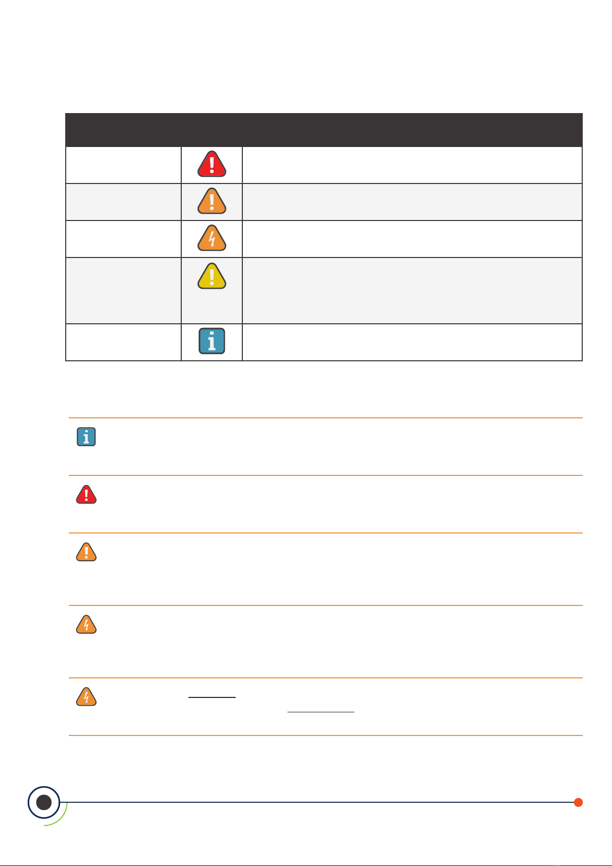
1.2.2 Iconography
Alert Icon Description
DANGER Imminently hazardous situation which, if not avoided, will
result in death or serious injury.
WARNING Potentially hazardous situation which, if not avoided,
could result in death or serious injury.
WARNING Potential electrical shock hazard which, if not avoided,
could result in death or serious injury.
CAUTION
Potentially hazardous situation which, if not avoided,
could result in physical injury or damage to the product
or environment. It may also be used to alert against
unsafe practices.
IMPORTANT Additional information on how to use the product.
1.3. General Safety Statements
IMPORTANT: Before using this product, carefully read and strictly follow the
instructions in the manual. Ensure that all product documentation is retained
and available to anyone operating the instrument.
DANGER: This instrument is neither certied nor approved for operation in
oxygen-enriched atmospheres. Failure to comply may result in personal injury
or death.
WARNING: Under no circumstances should this product be operated without
connection to a protective ground. Failure to comply may result in a potential
shock hazard and is a violation of electrical safety standards applicable to this
category of equipment.
WARNING: Always remove AC power before working inside the AT-MGS-408
enclosure and exercise extreme care when accessing the products interior.
Only qualied electrical maintenance personnel should perform connections
and adjustments.
WARNING: DO NOT use soap and water or other detergents to clean the
outside of this product; use a DRY CLOTH only. Failure to comply may result in
a potential shock hazard.

3
AT-MGS-408 User Manual
CAUTION: The protection provided by this product may become impaired if
it is used in a manner not specied by the manufacturer. Modications to this
instrument, not expressly approved, will void the warranty.
CAUTION: In case of malfunction, DO NOT continue to use this equipment
if there are any symptoms of malfunction or failure. In the case of such
occurrence, de-energize the power supply and contact Aquilar on 01403
216100.
CAUTION: Use ONLY the provided cable glands for electrical and
communication wiring. Drilling into the box will void the warranty.

4
AT-MGS-408 User Manual
2. Product Description
2.1. Product Overview
The AT-MGS-408 Gas Detection Controller displays comprehensive and centralized
information about the status of all connected gas detectors. A maximum of eight
AquiTron gas detectors can be connected to the AT-MGS-408 via Modbus RTU.
Compatible gas detectors are:
• AT-MGS-410 • AT-MGS-550
• AT-MGS-450
• AT-MGS-460
The AT-MGS-408 can be used to provide power to each connected, compatible gas
detector, negating the need for separate power supply at the location of the gas
detector.
The AT-MGS-408 displays status via an LCD screen and a bank of LEDs that
represent the channel / sensor connected to it. Each channel / sensor has a row of
dedicated LEDs to indicate the status of the sensor:
• Power • Low alarm
• High alarm • Fault
The LCD screen will display the current gas reading and gas type for the selected
channel, or will indicate fault and/or alarm status. The LCD screen is also used for
conguration of the AT-MGS-408 via the integrated keypad.
In addition to the LED alarm status, the AT-MGS-408 includes an integrated audible
alarm. An optional beacon can be installed, mounted in the top of the enclosure, to
enhance local alarm indication.
The AT-MGS-408 provides relays (indicating any high alarm, low alarm or fault status) and
can act as a Modbus slave device. This allows connection to a third-party device such
as a Building Management System (BMS) or Programmable Logic Controller (PLC).
Data logging is available on the AT-MGS-408 via the integrated SD card, which can
be removed to allow download of the logged data to a computer. The data will

5
AT-MGS-408 User Manual
include a date stamp of all high and low alarms as well as all faults.
Figure 2-1 - AT-MGS-408 Gas Detection Controller with Optional External Beacon
WARNING: This instrument is neither certied nor approved for operation in
oxygen-enriched atmospheres. Failure to comply may result in EXPLOSION.
WARNING: For your safety, DO NOT use this instrument in locations classied
as hazardous because it has not been designed to be intrinsically safe for use
in such areas.
2.2. Intended Use
The AT-MGS-408 provides audio-visual alerts and information pertaining to the
status of a centralized gas detector network. This information allows concise, at-a-
glance notication of any alarm or fault status regarding a connected gas detector
located outside the monitored space, as required by many regulatory codes and
standards.

6
AT-MGS-408 User Manual
2.3. Design Features
Power Options 100 - 240 VAC, 50/60 Hz, 80 W (max.)
Provides power for 1 - 8 compatible AquiTron gas detectors
Output/
Communications
RS485 Modbus RTU Master for Gas Detectors
Diagnostic / Status LEDs
yController (power, fault)
yGas Detectors (power, fault, low alarm, high alarm)
Outputs
y3 × Relays (fault, low alarm, high alarm), Fail-safe Option
yRS485 Modbus RTU Slave
Optional
yExternal Beacon (red, blue, green, yellow)
Data Logging Via supplied 32GB SD card; will hold up to 10 years of
logged data.
User Interface LCD Display screen
Integrated keypad

7
AT-MGS-408 User Manual
2.4. Components
Figure 2-2 - Component Layout
MAINS WIRING: 12-18 AWG
(4.0-0.75 mm2) Strip Length
.43″ (11 mm). Depress and
insert wire into terminal
block.
DC, RELAY WIRING: 14-22 AWG
(2.08-0.37 mm2). Strip Length .25″ (6
mm). Torque: 31-35 in-oz (0.22-0.25
Nm).
RS-485, BEACON WIRING: 18-26
AWG (0.83-0.13 mm2). Strip Length
.20″ (5 mm). Torque: 31-35 in-oz
(0.22-0.25 Nm).
MEMORY CARD: Product
uses only SDHC memory
cards, formatted to FAT 32,
with a maximum capacity of
32GB.
DOWNLOAD INSTRUCTIONS: For more detailed product
information and an installation guide, scan here or visit
www.mybacharach.com to access the MGS-408 User Manual
(P/N: 1100-2295) and Quick Start Guide (P/N: 1100-2292).
# Component Description # Component Description
1AC Power Terminal Block 8High Alarm Relay
2Power Supply 9Fault Relay
3Cooling Fan 10 Sensor Power Connector
4SD Card Slot 11 Sensor Modbus Connector
5Coin Cell Battery 12 BMS Modbus Connector
6Reset Switch 13 AV Beacon Connector
(external beacon not shown)
7Low Alarm Relay
8
AT-MGS-408 User Manual
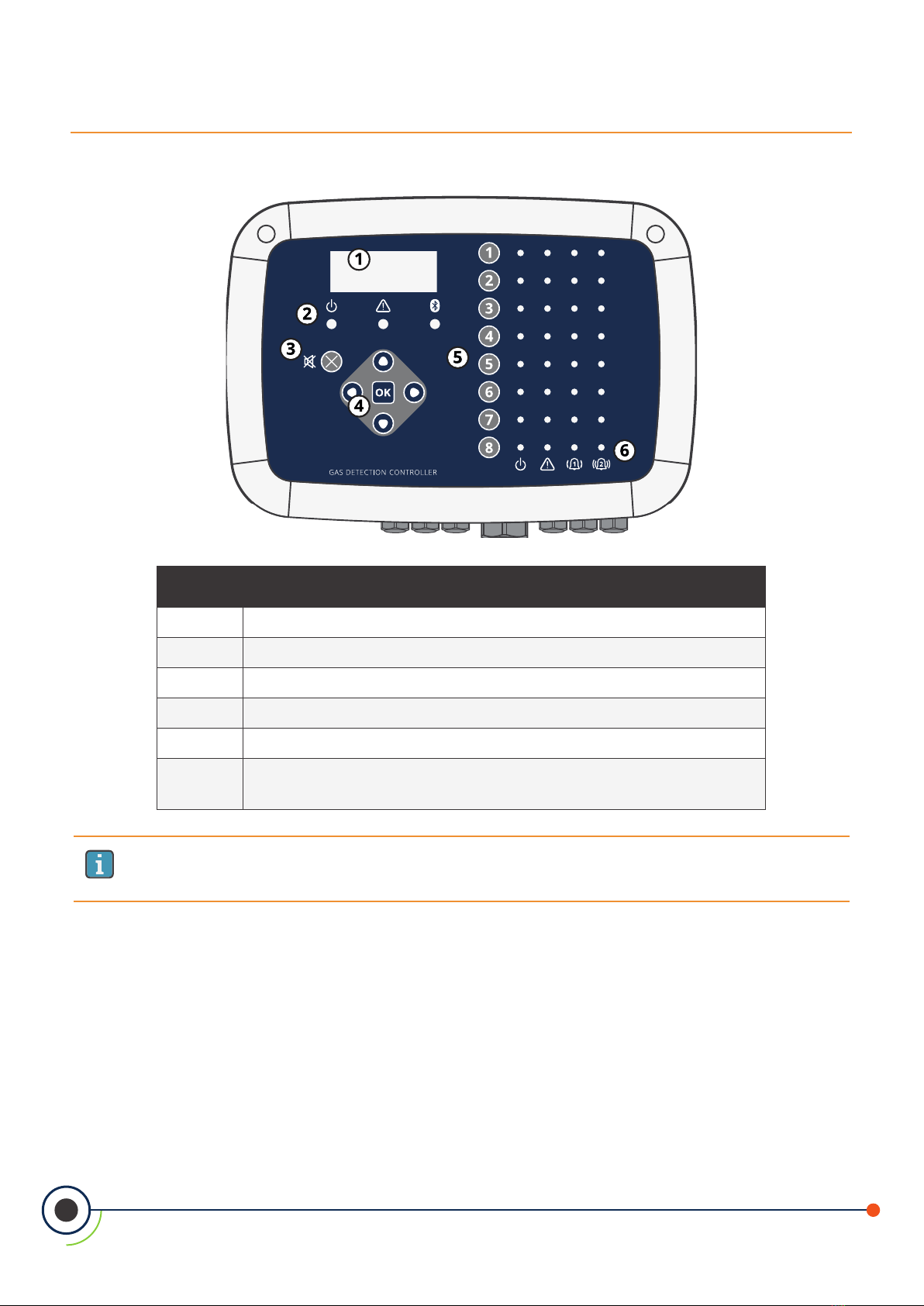
Figure 2-1 - Front Panel Layout
AT-MGS-408
# Component Description
1LCD Display
2Power, Warning and Bluetooth indicator LEDs
3Alarm Mute Button
4Main Keypad | Arrow and OK keys
5Channel Keys
6Power, Fault, Low Alarm (1), High Alarm (2) LEDs for each
sensor channel
IMPORTANT: Bluetooth LED indicates when a downstream sensor has
established a connection with the MGS-400 App.
2.5. Communication Features
The AT-MGS-408 Gas Detection Controller features full two-way communications
via an RS-485 interface. MODBUS RTU is the communication protocol standard.
The controller can be congured as a modbus master and be the centralized
location for all eight gas sensors or be the modbus slave and connect to a building
management system for a complete gas detection solution.

9
AT-MGS-408 User Manual
3. Installation
3.1. Warnings & Cautions
WARNING: Explosion hazard! Do not mount the AT-MGS-408 Gas Detection
Controller in an area that may contain ammable liquids, vapors or aerosols.
Operation of any electrical equipment in such an environment constitutes a
safety hazard.
WARNING: Electrical installation should be performed by a certied electrician,
and should comply with all applicable NEC / CEC and local electrical safety codes.
WARNING: The AC power ground wire must rst be connected to the monitor’s
ground terminal. Under no circumstances should this monitor be operated
without a protective ground. Doing so poses a potential shock hazard, and is
also a violation of electrical safety standards applicable to this type of equipment
WARNING: Shock hazard! Always turn o AC power before working inside
the monitor.
CAUTION: Drilling holes in the AT-MGS-408 Gas Detection Controller
enclosure may damage the unit and will void the warranty. Please use
provided cable glands for electrical connections.
CAUTION: The AT-MGS-408 Gas Detection Controller contains sensitive
electronic components that can be easily damaged. Be careful not to touch
or disturb any of these components.
3.2. Preliminary Inspection
The AT-MGS-408 Gas Detection Controller has been thoroughly inspected and
tested prior to shipment from the factory. Nevertheless, it is recommended that the
instrument be re-checked prior to installation. Inspect the outside of the enclosure
to make sure there are no obvious signs of shipping damage. Loosen the two screws
on the top of the enclosure lid and open the front panel. Visually inspect the interior
of the enclosure for loose wires or components that may have become dislodged
during shipment. If damage is discovered, please contact a qualied repair technician
or contact Aquilar Ltd.
10
AT-MGS-408 User Manual
3.3. Suitable / Appropriate Locations
The AT-MGS-408 Gas Detection Controller should be centrally located in the facility
(preferably outside of the mechanical room) and should be easily accessible for visual
monitoring and servicing. This is the “split architecture design” for safety of the operator.
Dirt, grease, and oils can adversely aect the operation of the controller. The controller
should be installed out of direct sunlight in a clean, dry area that is not subject to
temperature or humidity extremes. Installation in a mechanical room is acceptable
provided reasonable environmental conditions exist. If there is a question, consider
installing the unit outside of the mechanical room in a cleaner area of the facility.
The controller can be located up to 1,000 feet (305 m) from the furthest gas monitor
when using RS485 communications. The available distance is less when using the
controller as the power supply for down line gas transmitters. Careful attention to
voltage drop over distance with a suitable wire gauge employed is also required. (See
“3.6.1 AT-MGS-408 Gas Detection Controller Network” on page 12.)
The controller provides an interface by which you can monitor, acknowledge alarms,
and observe conditions inside the mechanical room.
3.4. Mounting the Gas Detection Controller
The AT-MGS-408 Gas Detection Controller should be installed plumb, level and
securely fastened to a rigid mounting surface. The enclosure utilizes four mounting
holes designed for #6 (or M3.5 or M4) pan head fasteners (included). Mounting holes
are located in the four corners of the enclosure, accessed by loosening the two
screws on the top of the enclosure lid and opening the front panel. Install and adjust
the screws as necessary to hold the unit securely against the mounting surface, close
the front panel and tighten the screws.
WARNING: Copper conductors for connection to supply mains must be
made in accordance with NEC / CEC and local codes.
NOTE: A certied AC power disconnect or circuit breaker should be mounted
near the controller and installed following applicable local and national
codes. If a switch is used instead of a circuit breaker, a properly rated
CERTIFIED fuse or current limiter is required to be installed as per local or
national codes. Markings for positions of the switch or breaker should state
(I) for on and (O) for o.
11
AT-MGS-408 User Manual
3.5. Electrical Wiring
The controller enclosure features two M20 cable glands that are intended for power
entry. If conduit is preferred, simply remove one of the M20 glands and install a
suitable ½″ conduit adapter.
Locate the AC power and Ground on the power input terminal block. Secure the
incoming AC power neutral (white / blue), live (black / brown) and ground wires to the
appropriate terminals, using a screwdriver on the press-to-release tabs.
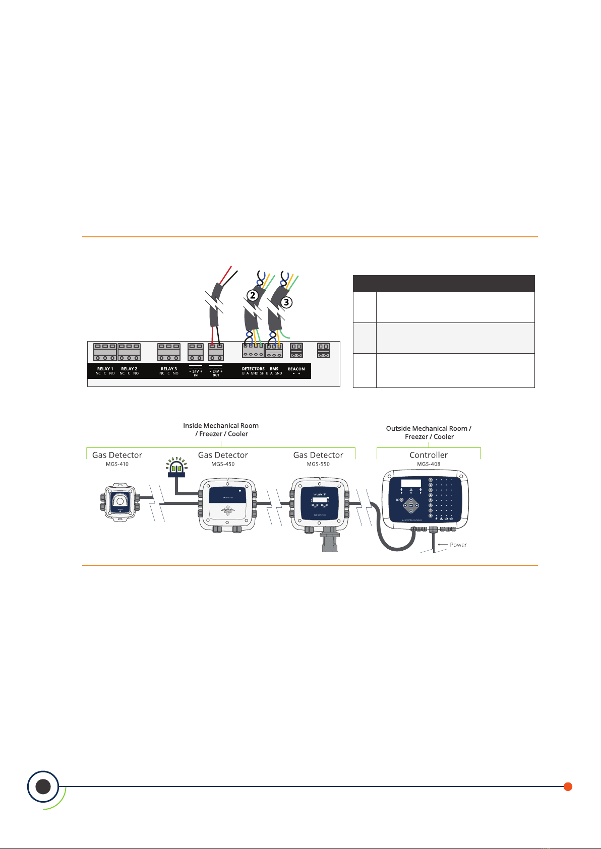
Figure 4-2 - AT-MGS-408 Wiring Diagram
AT-MGS-410
AT-MGS-450
AT-MGS-550
AT-MGS-408
# Description
124 V DC Out Connector to 24V DC
Power Supply
2RS-485 Modbus Connector to Gas
Monitor
3RS-485 Modbus Connector to
Building Management System (BMS)
12
AT-MGS-408 User Manual
3.6. Communications Connections
3.6.1 AT-MGS-408 Gas Detection Controller Network
The AT-MGS-408 Gas Detection Controller is connected to AT-MGS-410, 450, 460, 550
gas detectors using a shielded twisted pair instrument cable (Belden 3106A or equivalent).
The maximum distance between the AT-MGS-408 and the furthest AquiTron gas
sensor when using Modbus communications is 305M. This distance is reduced when
using the AT-MGS-408 as the power source for the AquiTron gas sensors due to
voltage drops in the cable. When using the AT-MGS-408 as a power source for the
AquiTron sensors the following needs to be taken into consideration; the total power
requirements of the sensors, the wire gauge of the cable being used and the distance
to the furthest gas detector.
NOTE: Recommended cable for Modbus and sensor power is 16-20AWG,
Belden 3106A shielded / twisted pair.
Power Requirements for AquiTron gas sensors
Model Load (W)
AT-MGS-410 4
AT-MGS-450 4
AT-MGS-460 4
AT-MGS-550 8
NOTE: When using an AT-MGS-550 Gas Detector with two sensors
connected it will count as (2) channels on the controller.
The maximum distance to the furthest sensor should not exceed the following lengths
based on the total power requirements of all of the sensors to be connected to the
AT-MGS-408; i.e., (8) AT-MGS-410 sensors is a total power of 32w.
The RS-485 communication wiring between the gas monitor and AT-MGS-408 Gas
Detection Controller must be connected in the following manner:
1. Locate the Modbus/RS-485 connector in the gas detector. (Refer to
“Figure 4-3 - AT-MGS-408 Wiring Diagram” on page 15. For additional
information, see appropriate gas monitor manual.)
2. Connect one lead of a twisted shielded pair to the “B” connection point;
note the wire color.
3. Connect the second wire to the “A” connection point; note the wire color.
4. Connect the ground to the “GND” connection point.
13
AT-MGS-408 User Manual
5. Connect the shield or drain wire to the “SH” connection point.
6. Locate the Modbus/RS-485 connectors in the AT-MGS-408 Gas Detection
Controller. The left Modbus/RS-485 connector (labeled “Detectors”) is for
down line “slave” devices (includes a dedicated shield position) and the right
Modbus/RS-485 connector (labeled “BMS”) is used to connect to “master”
devices up line, such as building management controls.
3.6.2 Integration with Building Management System
A second RS-485 connector allows a Building Management System to communicate
with the AT-MGS-408 Gas Detection Controller via Modbus protocol (see “5.2. MODBUS
Registers” on page 28). The connection is established using a shielded twisted pair
instrument cable (Belden 3106A or equivalent). Use any of the remaining service cable
glands to gain access to the interior of the AT-MGS-408 Gas Detection Controller.
Locate the Modbus/RS- 485 connector. Secure the wire leads to the connector in the
orientation as displayed on the board. Check to make sure the polarity matches the
wiring to the Building Management System. The shield connection should only be
grounded at the BMS device and should not be connected at the controller.
3.7. Connecting External Alarms
3.7.1 Overview
One switched 24 VDC contact marked “BEACON” is available for the connection of an
external beacon. The terminals can sink up to 300 mA at 24 VDC.
Form C relay contacts are provided for FAULT, LO ALARM and HI ALARM conditions.
3.7.2 Connection Guidelines
CAUTION: Use the remaining cable glands to gain access to the interior of
the controller. Drilling holes in the AT-MGS-408 Gas Detection Controller
enclosure may damage the unit and will void the warranty. Locate the
relay connectors. Secure the wire leads to the connectors.
NOTE: Power for the external alarms can be tapped o the AC IN connector.
NOTE: The relay contacts are rated 5A at 250VAC (N.O. contact) and 2A at
250VAC (N.C. contact). (Refer to “Figure 4-1 - AT-MGS-408 Wiring Diagram” on
page 15.)

14
AT-MGS-408 User Manual
4. Operation
4.1. Overview
4.1.1 Main Function
Every ve seconds the AT-MGS-408 Gas Detection Controller collects gas concentration
and status information from each connected gas detector. Gas concentration appears
on the LCD display and connection status, fault and alarm conditions are indicated
by the LED matrix for each channel. When an SD card is installed and data logging is
enabled (see Section 4.4 on page 24), concentration and status information is logged
every 10-seconds for all connected gas detectors. Detector data and controller status
information can also be communicated via MODBUS, to a master or BMS device.
4.1.2 Power Up
After power up, the rmware revision level will be indicated on the LCD followed by
an LED/LCD and beacon self test. The controller will then begin scanning connected
detectors and display their reported gas concentration on the LCD and status
information on the LED matrix.
4.1.3 Channel Number Keys
Pressing a Channel number key will bring up a scrollable channel detail screen with
detector specic information. Pressing the channel number key a second time will
access the channel setup menu.
4.1.4 Menu Access and Navigation
To access the System level menu:
Main Menu press OK. The currently selected menu item is indicated with triangle
pointers to the left and right of the description.
If the menu list is longer than can be displayed, up and down arrow keys on the
right side of the screen will indicate additional items are available by either scrolling
up or down.
Figure 4-3 - Main Menu

15
AT-MGS-408 User Manual
Some of the screens you will access will require data entry, such as the date/time
setup or location description. These screens will appear with a character selected,
as displayed below. Use the up / down Arrow keys to scroll through the characters
provided for that character’s place. Use the left / right Arrow keys to move the
cursor to the next character. When all character selections for the screen are
completed, press OK to accept the entries.
Figure 4-4 - Example of Data Entry Required
4.2. Controller Setup
Figure 4-5 - AT-MGS-408 Wiring Diagram
AT-MGS-410
AT-MGS-450
AT-MGS-550
AT-MGS-408
# Description
1
24 V DC Out
Connector to 24V DC
Power Supply
2
RS-485 Modbus
Connector to Gas
Monitor
3
RS-485 Modbus
Connector to Building
Management System
(BMS)
4.2.1 Setup Parameters
Before using the controller, various parameters must be set by the user based on

16
AT-MGS-408 User Manual
how the controller has been wired.
Main Menu CONTRLR CONFIG press OK, to access the setup parameters menu.
Figure 4-6 - Setup Controller Conguration
4.2.2 Relay Setup
To access the Relay setup menu:
Main Menu CONTRLR CONFIG RELAYS press OK.
From this menu, each of the three relays can be congured for either normal or
failsafe operation. The default is normal, meaning normally open contacts will close
with the event corresponding the relay designation. If fail safe is selected, the relay
will be normally energized and will be de-energized with the relays designated event
or a power failure.
To select the type of alarm for each relay:
Main Menu CONTRLR CONFIG RELAYS press OK to access the Relay setup
menu.
Press the Up/Down arrows to select relay, and press OK.
(The conguration type for the selected relay will begin to ash.)
Press the Right/Left arrow to change the conguration type, press OK.
Figure 4-7 - Relay Setup Menu
Figure 4-8 - Toggling the Alarm Setting
Table of contents


