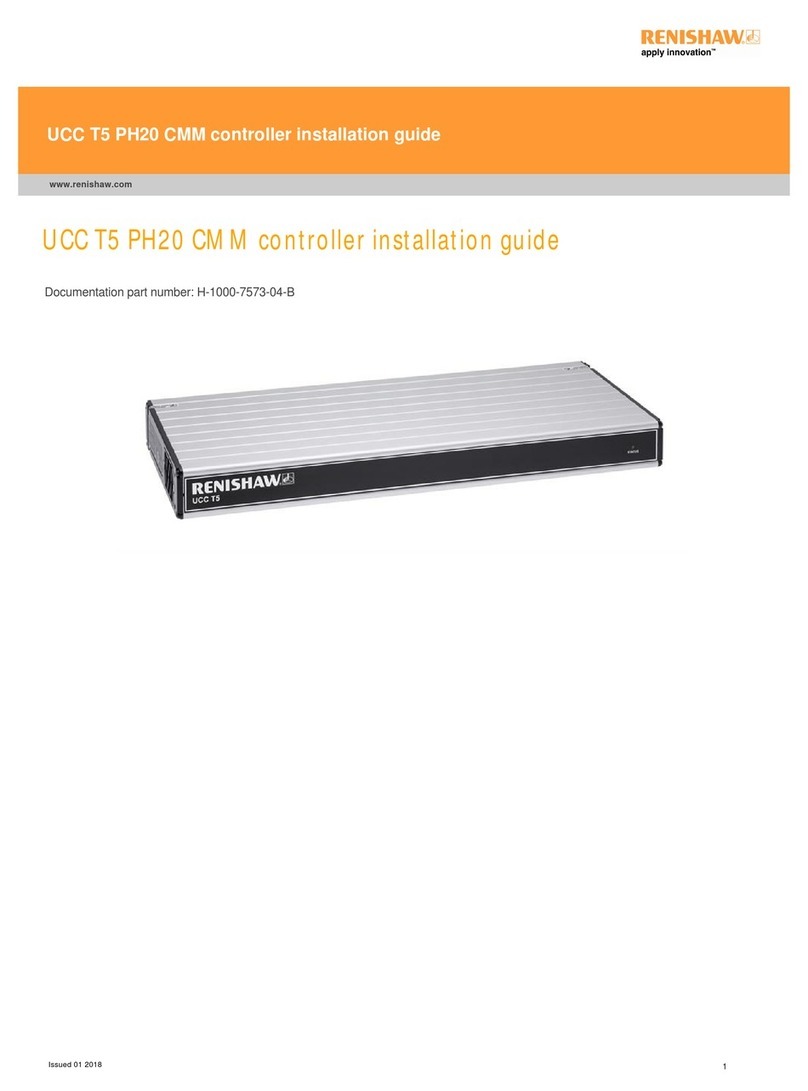
Renishaw UCC T3 User manual

General information
© 2012 ‐ 2013 Renishaw plc. All rights reserved.
This document may not be copied or reproduced in whole or in part, or transferred to any other media or language, by any means, without
the prior written permission of Renishaw.
The publication of material within this document does not imply freedom from the patent rights of Renishaw plc.
Disclaimer
RENISHAW HAS MADE CONSIDERABLE EFFORTS TO ENSURE THE CONTENT OF THIS DOCUMENT IS CORRECT AT THE DATE OF
PUBLICATION BUT MAKES NO WARRANTIES OR REPRESENTATIONS REGARDING THE CONTENT. RENISHAW EXCLUDES LIABILITY,
HOWSOEVER ARISING, FOR ANY INACCURACIES IN THIS DOCUMENT.
Trademarks
RENISHAW® and the probe emblem used in the RENISHAW logo are registered trademarks of Renishaw plc in the UK and other countries.
apply innovation is a trademark of Renishaw plc.
All brand names and product names used in this document are trade names, service marks, trademarks, or registered trademarks of their
respective owners.
Windows XP, Windows 2000, Vista, Windows 7 and Windows 10 are registered trade names of the Microsoft Corporation.
All trademarks and trade names are acknowledged.
WEEE
The use of this symbol on Renishaw products and/or accompanying documentation indicates that the product should not be mixed with the
general household waste upon disposal. It is the responsibility of the end user to dispose of this product at a designated collection point for
waste electrical and electronic equipment (WEEE) to enable reuse or recycling. Correct disposal of this product will help save valuable
resources and prevent potential negative effects on the environment. For more information, please contact your local waste disposal service
or Renishaw distributor.
Warranty
Renishaw plc warrants its equipment for a limited period (as set out in our Standard Terms and Conditions of Sale) provided that it is installed
exactly as defined in associated Renishaw documentation.
Prior consent must be obtained from Renishaw if non-Renishaw equipment (e.g. interfaces and/or cabling) is to be used or substituted. Failure
to comply with this will invalidate the Renishaw warranty.
Claims under warranty must be made from authorised service centres only, which may be advised by the supplier or distributor.
UCC T3 installation guide
www.renishaw.com
Issued 04 2019
2

Care of equipment
Renishaw probes and associated systems are precision tools used for obtaining precise measurements and must therefore be treated with
care.
Changes to Renishaw products
Renishaw reserves the right to improve, change or modify its hardware or software without incurring any obligations to make changes to
Renishaw equipment previously sold.
UCC T3 installation guide
www.renishaw.com
Issued 04 2019
3

EC declaration of conformity
Renishaw plc hereby declare that the UCC T3 controller is in compliance with the relevant provisions of directives 2004/108/EC and
2006/95/EC.
Contact Renishaw plc or visit www.renishaw.com/knowledgebase for the full EU declaration.
UCC T3 installation guide
www.renishaw.com
Issued 04 2019
4

FCC (USA only)
Information to user (47CFR section 15.105)
This equipment has been tested and found to comply with the limits for a Class A digital device, pursuant to Part 15 of the FCC rules. These
limits are designed to provide reasonable protection against harmful interference when the equipment is operated in a commercial
environment. This equipment generates, uses, and can radiate radio frequency energy and, if not installed and used in accordance with the
instruction manual, may cause harmful interference to radio communications. Operation of this equipment in a residential area is likely to
cause harmful interference, in which case you will be required to correct the interference at your own expense.
Information to user (47CFR section 15.21)
The user is cautioned that any changes or modifications not expressly approved by Renishaw plc or an authorised representative could void
the user's authority to operate the equipment.
UCC T3 installation guide
www.renishaw.com
Issued 04 2019
5

Safety
WARNING: Earthing provision for the complete machine is the responsibility of the OEM or installer.
WARNING: Isolation: UCC T3 is isolated from the dc power supply by disconnection of the power connector. If any additional
means of isolation is required, it must be specified and fitted by the machine manufacturer or the installer of the product. The
isolator must be sited within easy reach of the CMM operator and comply with IEC61010 and any applicable national wiring
regulations for the country of installation.
WARNING: The PSU must be single fault tolerant, approved to EN60950-1 and must be connected to a supply incorporating a
protective earth conductor. Earthing provisions and residual fault protection for the complete machine are the responsibility of the
OEM or installer.
Machine safety
WARNING: Switching off or isolating the UCC T3 may NOT prevent unexpected machine movement. The user is advised to isolate
the machine from the electricity supply, compressed air or other energy sources in accordance with the machine manufacturer's
instructions before entering the danger zone or performing any maintenance operations.
If the equipment is used in a manner not specified by the manufacturer, the protection provided by the equipment may be impaired.
The emergency stop safety system that has been integrated into the UCC T3 controller is designed to achieve category 2 to standard BS EN
ISO13849-1:2008, this can be hardware configured to obtain category B. The risk assessment made by the system installer on the installation
should therefore have determined which category is required.
The UCC T3 must only be commissioned through Renishaw software, failure to do so may result in unexpected machine movement.
UCC T3 installation guide
www.renishaw.com
Issued 04 2019
6

Environmental conditions
Indoor use IP30* (BS EN60529:1992)
Altitude Up to 2000 m
Operating temperature +5 °C to +50 °C
Storage temperature ‐25 °C to +70 °C
Relative humidity 80% maximum ﴾non‐condensing﴿ for temperatures up to +31 °C
Linear decrease to 50% at +40 °C
Transient voltages Installation category II
Pollution degree 2
* NOTE: It may be necessary to house UCC T3 in a suitable electrical enclosure according to the installation's environmental
conditions to obtain a higher IP rating.
NOTE: For ambient temperatures under 40 °C, maximum input power for the UCC T3 is 800 W. For temperatures between 40 °C
and 50 °C the maximum power is 400 W.
WARNING: UCC T3 is not recommended for use in ambient temperatures above 50 °C.
UCC T3 installation guide
www.renishaw.com
Issued 04 2019
7

System overview
UCC T3 is an addition to the Renishaw CMM controller product range. UCC T3 combines the control capabilities of UCClite-2 with the servo
power amplifier performance of the SPAlite, with enhancements for higher power and category 2 E-STOP.
The high power capability combined with the compact form of the UCC T3 controller-amplifier enables use across a wide range of machines.
The complete range of Renishaw two-wire kinematic touch-trigger probes is supported. Conventional contact and strain-gauge sensors and
manual and motorised probe heads with appropriate probe or stylus changers are supported only with additional hardware (for
example a PH10 PLUS head will need a PHC10-3 PLUS which will be connected to the serial comms port on the controller).
The UCC T3 CMM controller-amplifier has the following capabilities:
Controls three axes of a CMM
Accepts input signals from air pressure sensors, crash detectors and all axis inner and outer travel limit switches
Accepts two uncommitted general-purpose input signals and generates one uncommitted general-purpose output signal
Serial communication for use with a Renishaw PHC10-3 PLUS controller
Directly supports the TP1, TP2, TP6, TP20 touch-trigger probes
Indirectly supports the TP200 via an external PI 200-3 interface
Provides a +24 V supply for use by the CMM switches
Supports the MCUlite-2 joystick (it can also support the MCU5 and MCU W)
Provides power output of up to 800 W continuous and 960 W for up to 1 second
The voltage setting of each axis is independent, allowing differing motor voltages to be used without damage
Supports dc motors in the range 24 V to 80 V, currents up to 10 A
Supports encoder / tacho or linear encoders (torque mode) for velocity feedback
Simulated linear power amplifier - drive outputs are free from switching edges, eliminating noise from drive PWM improving repeatability
and reducing emissions
Provides category 2 E-STOP
UCC T3 installation guide
www.renishaw.com
Issued 04 2019
9

System features
The unit has the following facilities:
Rear panel connectors for the external interface cables to and from the CMM
Rear panel USB connection for the two-way communication link to the CMM host computer
Rear panel connection for a Renishaw MCU joystick
Readhead circuitry for CMM digital measuring scales and motor encoders
Digital servo power amplifier
Status-indicating LEDs
Control electronics for probes and peripheral devices attached to the CMM
LEDs visible through the front panel of the UCC T3 enclosure indicate the operational status
Sub-circuits in the unit control the following interfaces through connectors on the rear panel of the enclosure:
USB data link to the CMM host computer
X, Y, Z axis data input from the CMM readheads
Motor drives
Connections for the TP20, TP1, TP2 and TP6 touch-trigger probes
I/O connections to limit switches, air pressure sensors and other digital inputs and outputs
UCC T3 installation guide
www.renishaw.com
Issued 04 2019
10

System components
The part numbers of the UCC T3 kits and upgrades are:
UCC T3 kits
A-5518-0001 - UCC T3 controller-amplifier
A-5518-0501 - UCC T3 controller-amplifier kit 1 comprising:
A-5518-0001 - UCC T3 controller-amplifier kit
A-5331-0007 - MCUlite-2 joystick
A-5518-0020 - UCC T3 controller-amplifier kit 2 comprising:
A-5518-0001 - UCC T3 controller-amplifier kit
A-5331-0007 - MCUlite-2 joystick
A-5518-0025 - PSU 600 W 60 V + cable (medium / large machines)
UCC T3 accessories
A-5518-0005 - UCC T3 bracket kit
A-5518-0010 - UCC T3 connector kit (including USB cable)
A-5518-0011 - UCC T3 filter replacement kit
P-EA02-0021 - PSU 70 W 24 V (small machines)
A-5518-0025 - PSU 600 W 60 V + cable (medium / large machines)
A-5331-0007 - MCUlite-2 joystick
A-5121-0003 - MCU 5 joystick
A-5863-0100 - PHC10-3 PLUS head controller
A-5567-1622 - PHC10-3 RS232 comms cable
A-5707-0100 - PI 200-3 probe interface
UCC T3 installation guide
www.renishaw.com
Issued 04 2019
11

Installation software
UCCassist-2
The Renishaw UCCassist-2 program is a utility to assist the engineer to install, commission and maintain a CMM system based on the UCC
T3 controller-amplifier.
Capabilities of the software include:
Basic machine system diagnostics
Operation with Renishaw's machine checking gauge, enabling the user to complete frequent volumetric accuracy tests to ensure the CMM
is running within the specified operational tolerances
Automated CMM error-mapping routines, when used in conjunction with the Renishaw ML10 or XL80 laser systems
UCC T3 installation guide
www.renishaw.com
Issued 04 2019
12

CMM host computer for UCC T3 controller
installation
For the installation of a UCC T3 controller, the CMM host computer must use Windows XP Pro, Windows Vista or Windows 7 as an operating
system and a hard disc drive with available storage space of at least 300 Mbytes. The processor speed and RAM requirements are not
excessive - if the PC supports the operating system and application software, it will almost certainly support the UCC controller operation. A
minimum specification of 1 GHz processor speed and 256 Mbytes RAM is recommended but please check with your application software
vendor for their requirements, as they may be higher.
UCC T3 installation guide
www.renishaw.com
Issued 04 2019
13

General wiring standards for UCC T3
controller installation
To achieve reliable operation of the UCC T3 and the CMM host computer, the following should be observed:
The PSU must be single fault tolerant, approved to EN60950-1 and must be connected to a supply incorporating a protective earth
conductor. Earthing provisions and residual fault protection for the complete machine are the responsibility of the OEM or installer.
The system must be PAT tested before the equipment is powered.
All signal cables MUST be screened and all cable screens should be connected electrically to the cable connector's metal shells.
It is recommended that screens for motor cables should be connected to the shell on the UCC T3 end and connected to the motor housing
at the CMM end.
Signal cables such as tacho and scale cables should be connected to the UCC T3 and have a cable shield that runs to the machine but is left
unconnected at the machine end.
Motor screens should be connected to both the UCC T3 and the motor housing.
Please refer to appropriate product installation guides when other Renishaw components (PH10, PI 200 etc) are integrated into the system.
All cables that are used to connect the UCC T3 to the CMM (that are not data cables) must have a minimum cross section of 0.3 mm2 (as
specified in EN 60204-1 para.12.6). UCC T3 has a maximum voltage of 80 Vdc and peak current is 10 A. The actual peak current will be
dependent on the size of the motor fitted and how hard it needs to be driven, so cable sizes need to be calculated by the system installer.
All cable connectors should be secured to the UCC T3 by the connector jack screws.
The power input to the UCC T3 controller is via a 3W3 connector; refer to the 'Connectors and signals' section for more information.
UCC T3 power requirements
The UCC T3 controller requires 30 W of power to support the controller functions integrated into the unit; this must be factored into the
power supply used.
UCC T3 installation guide
www.renishaw.com
Issued 04 2019
14

UCC T3 controller troubleshooting
Fatal faults
The UCC T3 controller monitors a number of machine input / output signals and internal operational functions. If any of these reach a defined
level where the system believes it is dangerous to operate, a fatal fault will be applied.
When a fatal fault is detected it is not possible to engage the servo system. There may be other faults that prevent the CMM from engaging.
Not all are reported.
Reported fatal fault Possible cause
Emergency stop Emergency stop system activated
Internal failure of servo power amplifier
Air pressure Air pressure low
Crash Crash switch activated
Scale failure Scale readhead failed
Scale “mis‐count”
Scale not connected
Overspeed The position demand has exceeded an internal defined limit
Failure of a tacho feedback
Incorrect scale resolution
Over-temperature shutdown
The UCC T3 unit is designed for continuous power of up to 800 W. The unit will allow a supply current consumption of up to 12 A, which at
80 V is 960 W for a short period of time (1 second).
If this is sustained for a prolonged period, or the unit is not used in an adequate environment such as poor ventilation or high ambient
temperature, the unit will disengage the motors to protect itself. An over-temperature warning will be reported.
UCC T3 installation guide
www.renishaw.com
Issued 04 2019
15

Installation of the UCC T3
Mounting the UCC T3
The UCC T3 unit draws air from the right hand side when viewed from the front and expels air out of the left hand side. A minimum clearance
gap of 10 mm is necessary between the sides of the unit and any potential obstruction. The dimensions shown on the above drawing are in
mm (in).
Fitting mounting brackets for 19 inch rack mounting (optional)
Mounting kit (A-5518-0005)
NOTE: The screws supplied with this kit are M5 × 6 mm countersink type.
UCC T3 installation guide
www.renishaw.com
Issued 04 2019
16

System interconnections
The UCC T3 provides a simpler means of interconnecting many of the sub-systems (e.g. a probe head) in a measuring system.
TP2 / TP20 / TP6 - two-wire touch-trigger probe system for UCC T3 with manual
probe head
TP200 touch-trigger probe system for UCC T3
UCC T3 installation guide
www.renishaw.com
Issued 04 2019
17

UCC T3 visual diagnostics
A visual indication of the system status is provided by four LEDs on the front panel, providing assistance in diagnosing and rectifying system
faults.
LED status key Description
LED on (green / amber / red)
LED flashing off / on
LED flashing red / green
LED off
XAny condition
USB comms Servo status Probe seated Error Description
No power to UCC T3
X X Download successful,
amps not engaged
E-STOP released, amps
not engaged
X X Download failed, power
cycle required
X X E-STOP active
X X Axes engaged
X X Dynamic braking
X X Scale error
UCC T3 installation guide
www.renishaw.com
Issued 04 2019
19

UCC T3 start-up process
When powered on, a self-test and initialisation is performed.
USB comms Servo status Probe seated Error Description
No power to UCC T3
Power applied to UCC T3
Waiting for download
If any of the tests fail, the failure mode is indicated on the status LEDs after about 15 seconds. When power cycling, a minimum of 10 seconds
is recommended between power removal and reconnection.
After the UCC T3 has completed its self-test, the system is ready for the software to be downloaded. The sequence of the status LEDs is shown
below.
USB comms active Servo status Probe seated Error Description
Waiting for download
Downloading, USB data
being passed
X X Download successful
UCC T3 installation guide
www.renishaw.com
Issued 04 2019
20
Table of contents
Other Renishaw Controllers manuals

Renishaw
Renishaw UCC1 User manual

Renishaw
Renishaw PHC10-3 PLUS User manual

Renishaw
Renishaw UCC T3-2 User manual

Renishaw
Renishaw UCC dynamic mapping tool User manual

Renishaw
Renishaw UCC T3 PLUS User manual

Renishaw
Renishaw UCC T5 User manual

Renishaw
Renishaw MCU5 User manual

Renishaw
Renishaw PHC10-3 PLUS User manual

Renishaw
Renishaw UCC MMI-2 User manual

Renishaw
Renishaw UCC S5 REVO-2 User manual
Popular Controllers manuals by other brands

Agilent Technologies
Agilent Technologies 4UHV user manual

Siemens
Siemens UP 520/31 Technical product information

Mitsubishi
Mitsubishi FX0N-16NT user guide

YOKOGAWA
YOKOGAWA YS80 Series technical information

Ropex
Ropex RESISTRON RES-5010 operating instructions

Dometic
Dometic Go Power GP-PWM-10-SQ user manual