aquilar AquiWave AQW-SK Installation instructions
AQW-SK
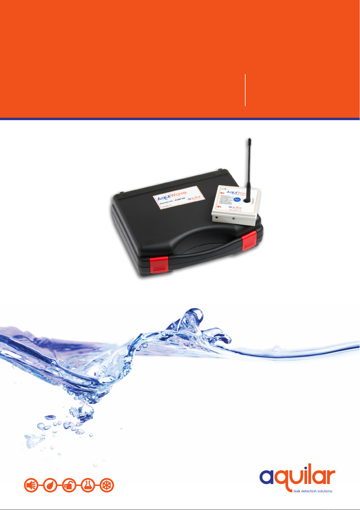
Survey Kit
AquiWave
INSTALLATION
& OPERATION
INSTRUCTIONS

Please read these
instructions carefully
and keep them in a
safe place (preferably
close to the module)
for future reference.
These instructions
must be followed
carefully to ensure
proper operation.
AQW-SK
Survey Kit
A. GENERAL INFORMATION
The AquiWave survey kit should only be used for performing radio surveys for the AquiWave
leak detection system. It works on the 868MHz frequency.
Each AquiWave installation will be dierent. For every building will have its own characteristics
with regard to radio suitability. It is therefore imperative a wireless site suitability survey is
carried out to ensure the system will function correctly.
The site suitability survey is an essential part of the design process and its accuracy will
determine whether the system will be able to reliably report any leaks. Assumptions should not
be made as hidden services within walls or ceilings could have a detrimental eect on the radio
signal, any short cuts or mistakes could result in leaks not being reported back to the main
control panel.
LEAK DETECTION SOLUTIONS
1
B. SURVEY CONTENT
• 1 x AQW-SK-RX - Survey detector
• 1 x AQW-SK-TX – Survey transmitter
• 1 x AQW-SA – Stub antenna
• 1 x AQW-SK-TX mounting bracket
• Extension poles (not usually required)
C. TURNING THE UNITS ON AND OFF
Before beginning the survey the RX and TX units must be powered up.
It is advisable to power up the TX rst. After tting the antenna press and hold the power
button for 3 seconds. When the unit beeps release the button and the red LED should be
illuminated.
To power up the RX press and hold the large white button for 3 seconds, ensuring the ‘in
contact’ button on the rear of the unit is not pressed in. Release the button when the unit
beeps. The LED will ash green then red. The LED will then turn o and the unit will tick to show
it is ready to use.
If the LED’s ash red on either unit the batteries are low. Please see section 7.
The RX and TX units must be powered down after use by holding the button down for 3
seconds.
There is no auto power o on either unit.
Unit 30, Lawson Hunt Industrial Park,
Broadbridge Heath, Horsham, West Sussex,
RH12 3JR
+44 (0) 1403 216100
www.aquilar.co.uk
D. TRANSMITTER POSITIONING AND MOUNTING BRACKET
It is important the AQW-SK-TX radio transmitter be positioned in the exact position the control
panel is to be mounted with the antenna in a vertical orientation. Failure to do this may
invalidate the survey.

AQW-SK
Survey Kit
LEAK DETECTION SOLUTIONS
2
E. PERFORMING THE SURVEY
To ensure the system works as expected it vitally important that every intended AQW-RTX
position is surveyed accurately. We would recommend making a note, on a plan if available, of
the exact position.
Ensure both units are powered on (see section 3). The red LED is illuminated on the TX and a
ticking can be heard from the RX. To test functionality press the ‘in contact’ button on the rear
of the RX. The RX LED should illuminate green and the unit beep tree times to indicate good
signal strength.
Now each AQW-TX location should be visited. Place the RX in the intended position ensuring the
in contact button on the rear of the unit is pushed in.
Once in position the unit will indicate signal strength as described in the table below:
LED Sound Status Action
Green 3 Pulses Good Fit AQW-RTX
Green 2 Pulses Average Fit AQW-RTX
Green 1Pulse Adequate Fit AQW-RTX, consider
tting booster
Red 2 Tone Unsatisfactory Relocate AQW-RTX,
or re-test after tting
Signal Booster
Red None No Signal Add Signal Booster
A 2 tone beep accompanied by a red LED indicates an acceptable signal may be found by
relocating the device to a nearby location.
If the LED is red with no beep then no signal is being received and a booster panel must be
considered, see section 6.
Unit 30, Lawson Hunt Industrial Park,
Broadbridge Heath, Horsham, West Sussex,
RH12 3JR
+44 (0) 1403 216100
www.aquilar.co.uk
The mounting bracket can be used to stick the TX to a wall if necessary, or wedge in to a
suitable object such as a ling cabinet.
Care should be taken when positioning the TX as dropping it could cause calibration damage
that may aect the survey accuracy.
F. SURVEYING FOR BOOSTER PANELS AND WIRED
ANTENNAS
If the AQW-SK-RX indicates no signal in an area where leak detection is required, then an AQW-
RBP booster panel or AQW-IA wired antenna must be used to extend the signal range to the
area in question.
For increased reliability Aquilar recommend using AQW-RBP or AQW-IA devices to extend signal
where only adequate signal is present.

AQW-SK
Survey Kit
LEAK DETECTION SOLUTIONS
3
G. BATTERIES
Low battery warning is indicated by a red ashing LED on either of the units. Batteries should
be checked prior to each survey visit to ensure they are not low.
To replace the batteries on either unit power down rst. The remove the cover and replace.
Care should be taken when tting the new battery pack to align the pins correctly. Only use
AQW-BP (6770) battery packs (1 x pack per unit).
If the LED on either devices starts ashing during a survey it is OK to continue. However
batteries should be replaced before the next survey.
Aquilar recommends the batteries are replaced every 100 hours or 12 months of use,
whichever occurs sooner.
Unit 30, Lawson Hunt Industrial Park,
Broadbridge Heath, Horsham, West Sussex,
RH12 3JR
+44 (0) 1403 216100
www.aquilar.co.uk
AQW-RBP-1/2 units require a 230Vac supply from an unswitched fuse spur. The booster panel
must be placed within radio signal range of the control panel to be able to relay information.
Use the AQW-SK-RX to locate a suitable location taking into consideration availability of
mounting space and power requirements. The AQW-SK-TX should then be positioned at this
location, observing the same rules as with the control panel (ie. antenna in a vertical position,
matching the booster panels intended antenna position) and the survey continue as previously.
AQW-IA wired antennas do not need to be within a signal area as they are hard-wired back to
an AQW-RCP control or AQW-RBP booster panel. Maximum cable run is 100m of 2 x twisted
pair 4 core data cable. Power for the AQW-IA is supplied from the control or booster panel. As
with the booster panel once a suitable location has been established the AQW-SK-TX should be
placed in this position and the survey continued.
Use the AQW-SK-RX to locate a suitable location taking into consideration availability of
mounting space and power requirements. The AQW-SK-TX should then be positioned at this
location, observing the same rules as with the control panel (ie. antenna in a vertical position,
matching the booster panels intended antenna position) and the survey continue as previously.
AQW-IA wired antennas do not need to be within a radio signal area as they are hard-wired
back to an AQW-RCP control panel or AQW-RBP booster panel. Maximum cable run is 100m of
2 x twisted pair 4 core data cable. Power for the AQW-IA is supplied from the control or booster
panel. As with the booster panel once a suitable location has been established the AQW-SK-TX
should be placed in this position and the survey continued.
Problem:
RX/TX unit(s) not powering up.
Possible Cause:
Battery power low
Action:
Replace battery pack
H. TROUBLESHOOTING
Problem:
No Red LED displayed when AQW-SK-TX
powered up. Or no ticking sound when
AQW-SK-RX powered up.
Possible Cause:
Initialisation fault, or battery low power
Action:
Cycle power on device. If problem
persists replace batteries.

AQW-SK
Survey Kit
LEAK DETECTION SOLUTIONS
4
Important: All information, including illustrations, is believed to be reliable. Users, however,
should independently evaluate the suitability of each product for their application. Aquilar
Limited makes no warranty as to the accuracy or completeness of the information, and
disclaims any liability regarding its use. The only obligations of Aquilar Limited are those in
the Aquilar Standard Terms and Conditions of Sale for this product, and in no case will Aquilar
Limited be liable for any incidental, indirect, or consequential damages arising from the sale,
resale, use or misuse of the product. Specications are subject to change without notice. In
addition, Aquilar Limited reserves the right to make changes – without notication to Buyer
– to processing or materials that do not aect compliance with any applicable specication.
AquiTron is a trademark of AquiTron Limited
Aquilar is a trademark of Aquilar Limited
V2 5.2020
Problem:
AQW-SK-TX survey transmitter will not power
up, changing batteries has no eect
Possible Cause:
Power link in ‘o’ position or removed
completely.
Action:
Check power link is tted and in the correct
position. Within the device to the left of the
battery pack is a 3 pin connector. The link
should be in the left hand position (middle
and pin closest to the battery pack) otherwise
the unit will not power up.
Problem:
AQW-SK-RX survey receiver will not power up,
changing batteries has no eect.
Possible Cause:
Power link in ‘o’ position or removed
completely.
Action:
Check power link is tted and in the correct
position. A 4 pin connector is located on the
base of the device. The link should be in the
left hand ‘ON’ position otherwise the unit will
not power up.
Problem:
Devices keep turning themselves o
Possible Cause:
Battery power is too low
Action:
Replace battery pack
TROUBLESHOOTING CONT. Problem:
Signal strengths on installed panel dierent
to indicated during survey
Possible Cause:
1. Panel and/or antenna not installed in
same position as survey transmitter
during survey.
2. AQW-RTX not located in same position as
survey receiver during survey.
3. Building/oce/equipment layout has
changed since survey.
Action:
Relocate devices to surveyed positions,
or add wired antennas/radio boosters to
provide adequate signal.
Problem:
No signal indicated on receiver during survey
Possible Cause:
1. Battery low in receiver
2. Out of transmitter range
3. Survey equipment out of calibration
Action:
Replace battery. Move within TX signal range
or add booster/wired antenna to survey.
Survey equipment should be re-calibrated
every two years.
Unit 30, Lawson Hunt Industrial Park,
Broadbridge Heath, Horsham, West Sussex,
RH12 3JR
+44 (0) 1403 216100
www.aquilar.co.uk
Table of contents
Other aquilar Measuring Instrument manuals


