aquilar Aquitron User manual
AquiWave
Wireless Leak Detection System
Aquitron
INSTALLATION
INSTRUCTIONS

INSTALLATION ITEMS
(NOT SUPPLIED)
• Wall fasteners for surface mounting (four
screws)
• Rubber or elastomeric washers to seal
at mounting points
• Semi-ush recess ange (optional)
TOOLS REQUIRED
• Drill or hole punch for electrical
conduit entries
• Phillips (cross-head) screwdriver
• Small at-head screwdriver
STORAGE
Keep the module in a dry place prior to
installation to avoid possible damage to
internal components.
ADDITIONAL ITEMS
Please read these
instructions carefully
and keep them in a
safe place (preferably
close to the module)
for future reference.
These instructions
must be followed
carefully to ensure
proper operation.
AquiWave™
Wireless Leak Detection System
A. GENERAL INFORMATION
Based on the same ultra-reliable technology used for radio re alarm systems since 1987. The
AquiWave wireless leak detection system has been designed to be capable of handling 240
devices. Typical installations would include small oces, private houses, guesthouses and small
hotels and any location where traditional wired leak detection would be a problem to install.
This manual contains information to enable an engineer to install, service and operate the
AquiWave control panel and the range of AquiWave devices. This product should be installed,
commissioned and maintained by qualied service personnel in accordance with codes of
practice, statutory requirements and IEE regulations for electrical equipment in buildings. The
system has been designed to allow very simple set up, with a user friendly menu structure
and full-text capability. There is no need to connect devices with a programming lead, as
conguration is achieved by radio. Text locations can be entered on the panel itself or by
connecting a standard USB keyboard to the panel. Prior to installation, the building where the
system is to be installed must be surveyed to ensure that each device to be tted has a good
radio communication path to the control or booster panel. This is done with an AW-Survey Kit.
When installing devices, they must be positioned as per the survey. Installing a device even a
few inches from the surveyed position can aect the signal strength signicantly, especially if
any metalwork is contained in the ceiling above the new position (e.g. air-conditioning ducting).
IMPORTANT
Failure to perform an accurate survey could result in the system being unreliable. These errors
can be costly to correct
• Position the panel where it is to be installed.
• Ensure devices are surveyed for their exact positions. A few inches either side may
substantially aect the signal strength.
• In order to have an accurate survey the batteries in the survey detector should be changed at
least once a year.
LEAK DETECTION SOLUTIONS
Weights & Measures House, 20 Barttelot Road,
Horsham, West Sussex RH12 1DQ
+44 (0) 1403 216100
www.aquilar.co.uk
1

AquiWave™
Wireless Leak
Detection System
LEAK DETECTION SOLUTIONS
Weights & Measures House, 20 Barttelot Road,
Horsham, West Sussex RH12 1DQ
+44 (0) 1403 216100
www.aquilar.co.uk
2
MAXIMUM NUMBER OF ZONES
20
MAXIMUM NUMBER OF DEVICES
240
MAXIMUM NUMBER OF REPEATER
PANELS
7
MAXIMUM TOTAL NUMBER OF
ANTENNAS
15
DIMENSIONS (W X H X D)
275 x220 x 85mm not including antenna
WEIGHT
4kg Not including battery
OPERATIONAL TEMPERATURE
-5oC to +40oC
IP RATING
IP30
ALARM INDICATORS
Twin ashing red LEDs
LEAK message on LCD with 40 characters of
text
FAULT INDICATORS
Amber LEDs and LCD providing details and
location of fault with 40 characters of
location text
EVENT LOG MEMORY
1000 events maximum
MAINS SUPPLY
230V 50Hz 0.3A max
MAINS FUSE
1 x 250V 3.15A
BATTERY
1 x 12V 7.0Ah sealed lead acid giving 72 hour
standby
BATTERY FUSE
1 x 250V 3.15A
RELAY FUSES
4 x 250V 500mA
RS485 FUSE
1 x 250V 500mA
INPUTS
2 x wired monitored circuit. 4k7Ω (±5%) end
of line (EOL) resistor monitored for open and
short circuit, 470Ω (±5%) alarm load
RELAYS
4 x programmable
Leak Relay: Clean Contact
Fault Relay: Clean Contact
Fault Relay Safe: Clean Contact
Accessory Relay: 10-18V, 500mA, 4k7Ω (±5%)
EOL
Monitored Relay 10-18V, 500mA, 4k7Ω (±5%)
EOL
OPERATING FREQUENCY
868MHz (868.025 to 868.575MHz)
MODULATION
2-GFSK
OUTPUT POWER (ERP
<25mW (<14dBm)
CHANNEL SPACING
50KHz
ERROR CHECKING
CRC
ERROR CORRECTION
Hamming
NUMBER OF CHANNELS AVAILABLE
12
COMPATIBLE WITH
AquiWave products only
PROTOCOL
ZPNet V1.00
B. SPECIFICATIONS

LEAK DETECTION SOLUTIONS
Weights & Measures House, 20 Barttelot Road,
Horsham, West Sussex RH12 1DQ
+44 (0) 1403 216100
www.aquilar.co.uk
3
AquiWave™
Wireless Leak
Detection System
CONTENTS
1.0 Installation
1.1 Contro Panel Installation
1.2 Transmitter Installation
2.0 Front Panel Layout
3.0 User Operation
3.1 System Normal
3.2 Fault Conditions
3.3 Silence Buzzer
3.4 Reset a Fault
3.5 Alarm Conditions
3.6 Silence the Alarm
3.7 Re-sound the Sounders
3.8 Reset the Alarm
3.9 Access Levels
4.0 Manual Operation
4.1 Quick Menu
5.0 Setup Menu
5.1 Time and Date
5.2 Access Codes
5.3 Default Access Codes
5.4 Programming Agent Details
5.5 Panel Information
5.6 Set up a New System (Standard)
5.7 User Options
5.8 System Options
5.9 Fault Options
5.10 User Tones
5.11 User Relays
5.12 Input Options
5.13 Input Text
5.14 Keyswitch Options
5.15 Panel Text
5.16 SIM Operations
5.17 Device Assignment
5.18 Panel Assignment
5.19 Add Antenna
5.20 Add Repeater/Booster Panel
5.21 Add Pager
5.22 Remove Hardware
5.23 Panel Network
5.24 Network Auto Congure
5.25 Device Information
5.26 Add Device
5.27 Remove Device
5.28 Remove All Devices
5.29 Edit Device
5.30 Device Text
5.31 Reprogram Device
5.32 System Test
6.0 Disable/Enable Menu
7.0 Test Mode
7.1 Test Zone
7.2 Clear Zone In Test
7.3 Lamp and Buzzer Test
7.4 System Test
7.5 Disable System Test
8.0 Event Log
8.1 Alarm Counter
8.2 View Event Log
8.3 Clear Event Log
8.4 Dump Event Log to USB
8.5 Save Event Log
8.6 View Saved Log
8.7 Shutdown Log
9.0 Verify Table
9.1 View Summary
9.2 View Detailed
9.3 Clear Verify Table
9.4 Dump Table to USB
9.5 View Panel Table
9.6 Clear Panel Table
10.0 View Airwaves
11.0 Battery Reset
12.0 Faults
12.1 Device Faults
12.2 Panel Faults
13.0 Delays
14.0 Common Problems & FAQ
15.0 Maintenance
16.0 Component Replacement
17.0 AquiWave Compatible Hardware

LEAK DETECTION SOLUTIONS
Weights & Measures House, 20 Barttelot Road,
Horsham, West Sussex RH12 1DQ
+44 (0) 1403 216100
www.aquilar.co.uk
AquiWave
Wireless Leak
Detection System
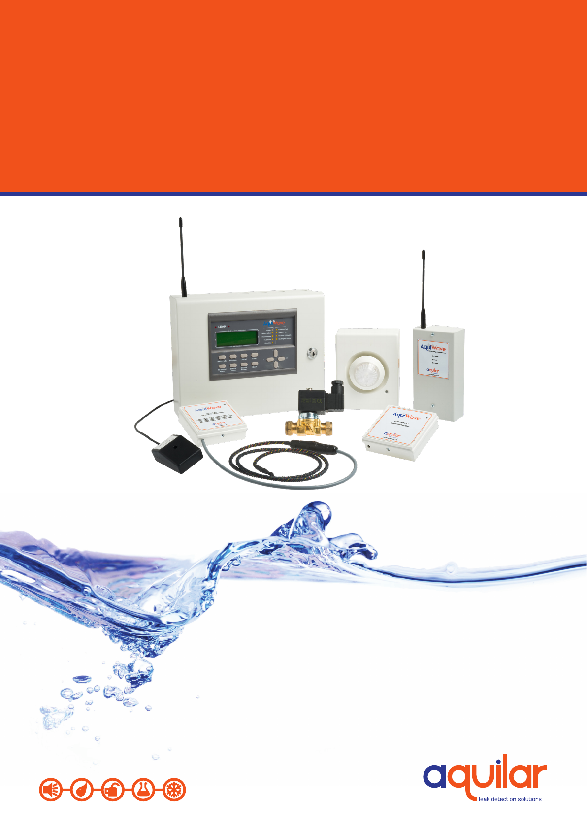
1.1 CONTROL PANEL
INSTALLATION
The electronic components within the panel
are vulnerable to electrostatic discharges. It
is advisable to wear a wrist strap designed to
prevent the build-up of static charges within
the body before handing any electronic
components. Do not remove or unplug any
components while the panel is powered up.
MOUNTING
The panel should be mounted on an internal
wall in a suitable position. If tted, the
antenna should be away from any solid
objects, especially electronic equipment and
metal structures. The wall should be even,
clean and dry and not prone to vibration.
Should the wall not be level, the panel
should be mounted on a wooden board. The
temperature should be in the range of -5oC
to +35oC and the humidity should not exceed
95%. Mount the panel using 3 x No. 10 screws
of a suitable length, and ensure washers
(supplied) are used to meet the IP30 rating.
The smaller washer (25mm diameter) is to be
used for the mounting hole next to the PSU.
CABLING
A 230V AC 50Hz supply capable of providing
500mA with a minimum diameter of 7mm
and a maximum diameter of 10.5mm should
be derived from a separate fused spur. This
spur should not incorporate a switch and
should be labelled ‘Leak Alarm Equipment –
Do Not Switch O’. A cable with a core cable
size no greater than 2.5mm2 should be
used. Always ensure that the mains supply
is completely isolated before working on any
mains rated components.
Cables should only enter the panel housing
through the knockouts provided. Do not
remove more knockouts than is needed
to terminate the cables, as additional
apertures in the panel will compromise the
ingress protection. A nylon M20 IP66 cable
gland should be used. The cable should be
connected to the terminal block as labelled
from above with the Live (brown) connected
to the top terminal, the Earth (green/yellow)
to the middle and the Neutral (blue) to the
bottom. Care should be taken to ensure no
loose strands protrude from the terminal
block and that the wire insulation is trimmed
to the correct length so that no exposed
wire is left visible. Any earth cables should
not be removed. Once the connection has
been made, the panel fuse (3.15A ceramic T
type) should be removed from the panel by
pulling on the fuse holder. The fused spur
can then be energised. To power up the
panel, insert the fuse holder with the correct
value of fuse tted. As there is a high inrush
current there is likely to be a spark produced.
This is normal. Mains power should always
be applied prior to connecting the standby
battery. Once the mains supply has been
applied, the green LED on the bottom edge
of the processor board should begin to ash
once a second. The system normal screen
will be displayed. Connections to the panel
inputs should be made using 2 core cable
with a core diameter of 1.0mm2. A nylon M20
IP66 cable gland should be used. A suitable
core diameter should be used depending on
the loading of the circuit. The Panel has been
type approved to IP rating IP30.
BATTERY
An AT-BU (part no: 3485) battery should
be tted. This will give a 72 hour standby,
assuming no external equipment (e.g.
wired antennas) has been added. Connect
the battery using the supplied terminal
connections. The red wire is +12V and the
black wire is 0V. Do not confuse the colour of
the terminal connectors. Once connected, the
Reset button on the keypad can be pressed. If
‘Battery Fault’ appears; check the connections
and polarity. If the battery is connected
4
LEAK DETECTION SOLUTIONS
Weights & Measures House, 20 Barttelot Road,
Horsham, West Sussex RH12 1DQ
+44 (0) 1403 216100
www.aquilar.co.uk
AquiWave
Wireless Leak
Detection System
incorrectly it is likely that the fuse will blow.
The wiring should be corrected and the fuse
The PSU will only charge batteries measuring
10.5V and above. Batteries measuring less
than 10.5V are regarded by the system as
faulty and will not be charged. A ‘Battery
Fault’ will be displayed on screen. If the
battery voltage is below 10.5V it will need to
be removed from the panel to be charged
and reconditioned, or replaced. The battery
voltage can be viewed on the PSU Info section
of the 5.5 – Panel Info menu. When replacing
the battery always do so with a product
of equal specication. Always dispose of
batteries responsibly. Never dispose of
batteries in general waste. If unsure contact
your local authority for guidance.
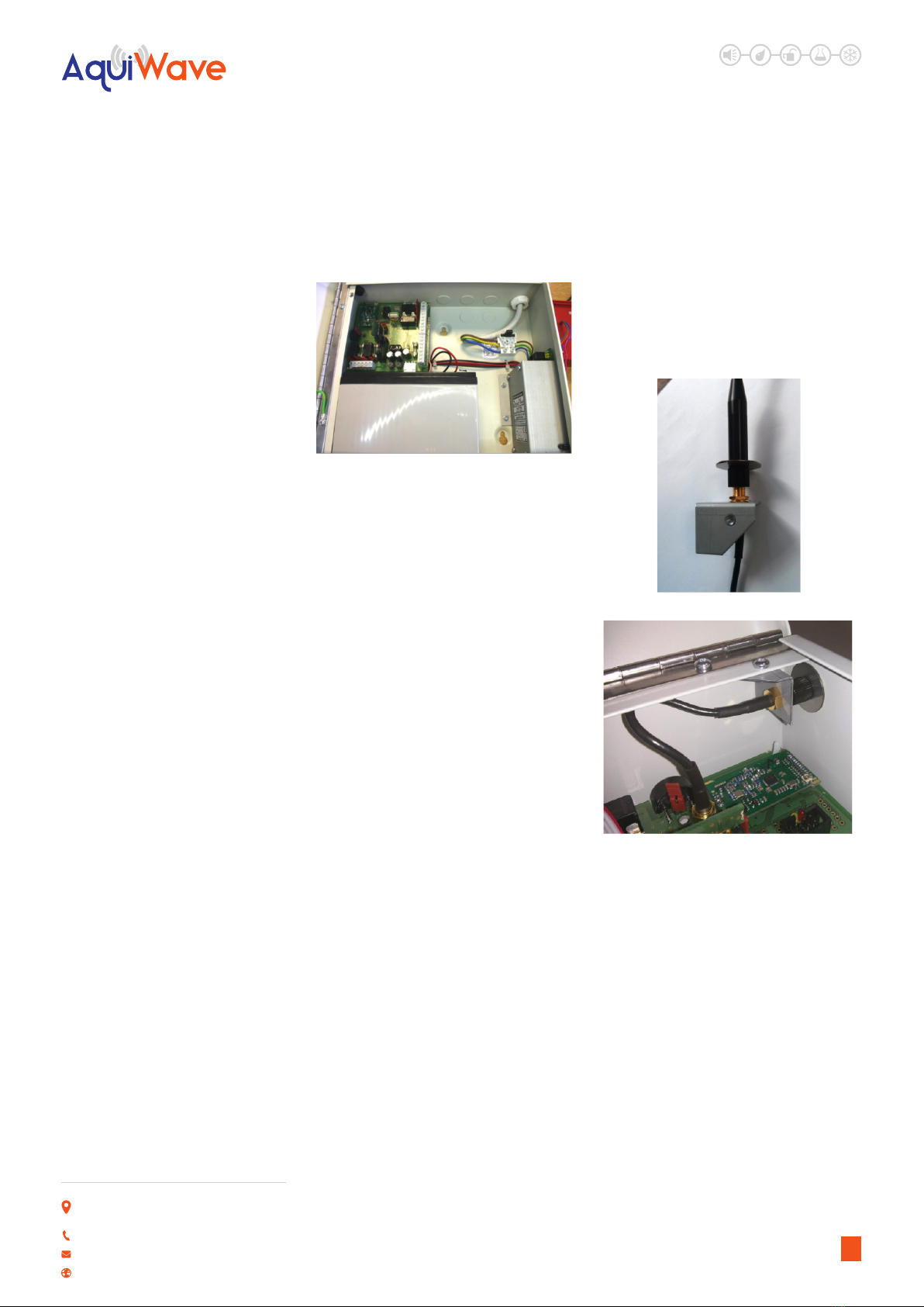
ANTENNA (IF FITTED)
The standard helical stub antenna (part
no: 6775) supplied with the panel should
be tted to the antenna bracket assembly
before it is mounted into the panel. Fit the
antenna onto the SMA connector as shown
below. This should be screwed hand tight.
Over tightening will cause the antenna to
break. The supplied antenna retaining washer
should then be placed over the top of the
antenna. The antenna and bracket assembly
should then be inserted through the antenna
aperture and mounted using the supplied M3
screw and an M3 serrated locking washer.
Once mounted, the antenna retaining washer
prevents the stub antenna being unscrewed
from outside the panel. Connect the antenna
assembly to the main processor board using
the SMA connector. If a high gain remote
antenna is being used, the stub antenna and
the antenna bracket assembly should be
removed. The new antenna should be tted
using a 50Ω SMA connector, suitable for use
with RG58 c/u coaxial cable, to the processor
board. When making o the cable, ensure
that no stray shielding wires are shorting.
Do not use non-radio connectors as they will
reduce the performance of the panel.
MONITORED INPUTS
The panel features two monitored inputs
that can be programmed either as latching
or non-latching. It is important to note that
before using these inputs they must be
enabled by programming them in the panel
options menu. If the inputs are enabled then
4K7Ω end of line resistors must be tted at
the termination. Applying a 470Ω resistor
across the inputs will produce a ‘LEAK’
message. The inputs are labelled ‘INPUTS’ and
‘No1’ and ‘No2’. These inputs can be assigned
a zone and text location, and then cause and
eects can be programmed for them. See
5.12 – Input Options for further information.
5

LEAK DETECTION SOLUTIONS
Weights & Measures House, 20 Barttelot Road,
Horsham, West Sussex RH12 1DQ
+44 (0) 1403 216100
www.aquilar.co.uk
AquiWave
Wireless Leak
Detection System
PCB LAYOUT
RS-485 CONNECTIONS
The RS485 connectors are used for wiring
hardware to the panel such as extra antennas
or a secondary display. A suitable data cable
should be used with 2 sets of twisted pairs.
Cat 5/5e/6 can be used but is not re rated.
Wired antennas and displays have two RS485
connectors, making it possible to make a
chain of up to 4 units. On the last unit in any
chain, a 100R resistor should be tted across
the D- and D+ terminals of the unused RS485
connection. If one of the control/booster
panel RS485 ports is unused then a 100R
should be tted between D- and D+. If none
of the panel RS485 ports are used then there
is no need to t the 100R resistor. The RS485
ports are capable of supplying 500mA at 15V.
PANEL RELAYS
The panel is equipped with four
programmable relays, each capable of
supplying 500mA. The total current draw
across all four relays must not exceed 1A. The
default relay types are:
Relay 1: Fault Relay - This activates on a fault
alarm condition. The default setting is Type
2 volt free fault relay. If set to type 3 or 5 the
relay can be used to power accessories (i.e.
Beacon or sounder). It switches 12V onto the
output and is monitored for short and open
circuit, with a 4K7Ω EOL. In this situation the
circuit should be connected between the C
and the NO terminals. The fuse should be
tted and the links put in the lower position.
Relay 2: Fault Failsafe Relay - This
energises on power-up and de-energises in
fault. Consequently the normally open and
normally closed terminals are reversed. The
fuse should be removed and the links tted
in the upper position as shown on the PCB
layout diagram.
6

LEAK DETECTION SOLUTIONS
Weights & Measures House, 20 Barttelot Road,
Horsham, West Sussex RH12 1DQ
+44 (0) 1403 216100
www.aquilar.co.uk
AquiWave
Wireless Leak
Detection System
Relay Type Normal State Contacts in Alarm Fuse EOL Link Position
1. Leak Relay Not energised Clean contact None None Up/Right
2. Fault Relay Not energised Clean contact None None Up/Right
3. Sounder Circuit -4.5V 500mA +15V 500mA 500mA 4K7 Down/Left
4. Fault Relay Safe Energised Clean contact None None Up/Right
5. Accessory Circuit -4.5V 500mA +15V 500mA 500mA 4K7 Down/Left
DISPLAY CABLE
A ribbon cable connects the two panel boards
together. It should be connected to the
system link/bus connections on the boards.
Do not remove or connect the ribbon cable
while the panel is powered up, as damage
can occur to the processor board.
BUZZER LINK
The buzzer can be disabled by removing the
buzzer link (see page 8 – PCB Layout).
MEMORY CARD
The memory card stores a complete set of
the system settings including device/zone
text and options. The memory card should
be tted at all times unless instructed by the
panel (i.e. when adding a repeater panel).
USB SOCKET
The USB socket can be used for connecting
a keyboard to program device text. It is also
used to plug in a memory stick to download
the event log, device info and the verify table
so a hardcopy can be retained for records.
1.2 TRANSMITTER (AQW-RTX) INSTALLATION
The AquiWave radio transmitter units (AQW-RTX) contain delicate electronic components and
should always be handled with care.
ON JUMPER POSITION OFF JUMPER POSITION
Power/Reset Jumper
Terminals
Power/Reset Jumper
Terminals
Relays 3 & 4: Leak Relays -Default setting
is volt free. These relays are each capable of
supplying 500mA at 12V. Both the sounder
circuit fuses should be tted in the fuse
holders and the links tted in the left or
lower positions as shown on the PCB layout
diagram. The circuit should be connected
between the S+ and the S- terminals. A
4K7Ω end of line resistor should be tted
to monitor the circuit. The relays can be
congured as accessory circuits, sounder
circuits, monitored outputs or volt free
clean contact relays. The relay type can
be changed in 5.7 – User Options and by
positioning the jumper links and fuses as
detailed below. When relays are congured
as ‘Volt Free’ accessory or as sounder circuits,
the associated terminal pin (V+) must not be
used.
7

LEAK DETECTION SOLUTIONS
Weights & Measures House, 20 Barttelot Road,
Horsham, West Sussex RH12 1DQ
+44 (0) 1403 216100
www.aquilar.co.uk
AquiWave
Wireless Leak
Detection System
When xing the AQW-RTX care must be
taken choosing its location. Consideration
must be given to its physical and potential
environmental surroundings. The transmitter
itself is not IP rated and must not be
positioned in an area that will get wet if a leak
occurs. It is recommended a leader cable be
run from the transmitter to the leak sensor,
positioned in the potentially wet area. If the
tamper feature is to be used, the transmitter
must be rmly xed back to an even surface.
IMPORTANT NOTE: It is important to locate
the transmitter in the position indicated
during the site suitability survey. Even
moving a small distance could potentially
aect its performance. If the AQW-RTX is
relocated, its radio connection to the system
in its new position must be veried as
suitable. If a descriptive location reference
has been added to the main control panel
programming, this should also be altered
accordingly.
Prior to xing a small 5.5mm hole should be
drilled into the bottom left corner of the back
box for leader cable entry.
8

LEAK DETECTION SOLUTIONS
Weights & Measures House, 20 Barttelot Road,
Horsham, West Sussex RH12 1DQ
+44 (0) 1403 216100
www.aquilar.co.uk
AquiWave
Wireless Leak
Detection System
The two core leader cable should be
terminated into the sensor cable terminals.
Only connect one leader cable/sensor to each
AQW-RTX.
Once the back box is in place and sensor
connected follow the instructions in
section 5.26 to add the device to the
system.
The AQW-RTX has anti-tamper and sensor
fault monitoring. Both removing the sensor
and/or the box will register as a fault on the
control panel.
The ant-tamper can monitor both device
removed and device open. Both are achieved
by using the spring loaded button positioned
on the back box.
NOTE : By default this is set for device
open only. For Device removal the
retaining clips must be removed to allow
the button to protrude from the rear of
the box. In this case the box must be xed
to a at surface to prevent a removal fault
showing on the control panel.
9
LEAK DETECTION SOLUTIONS
Weights & Measures House, 20 Barttelot Road,
Horsham, West Sussex RH12 1DQ
+44 (0) 1403 216100
www.aquilar.co.uk
AquiWave
Wireless Leak
Detection System
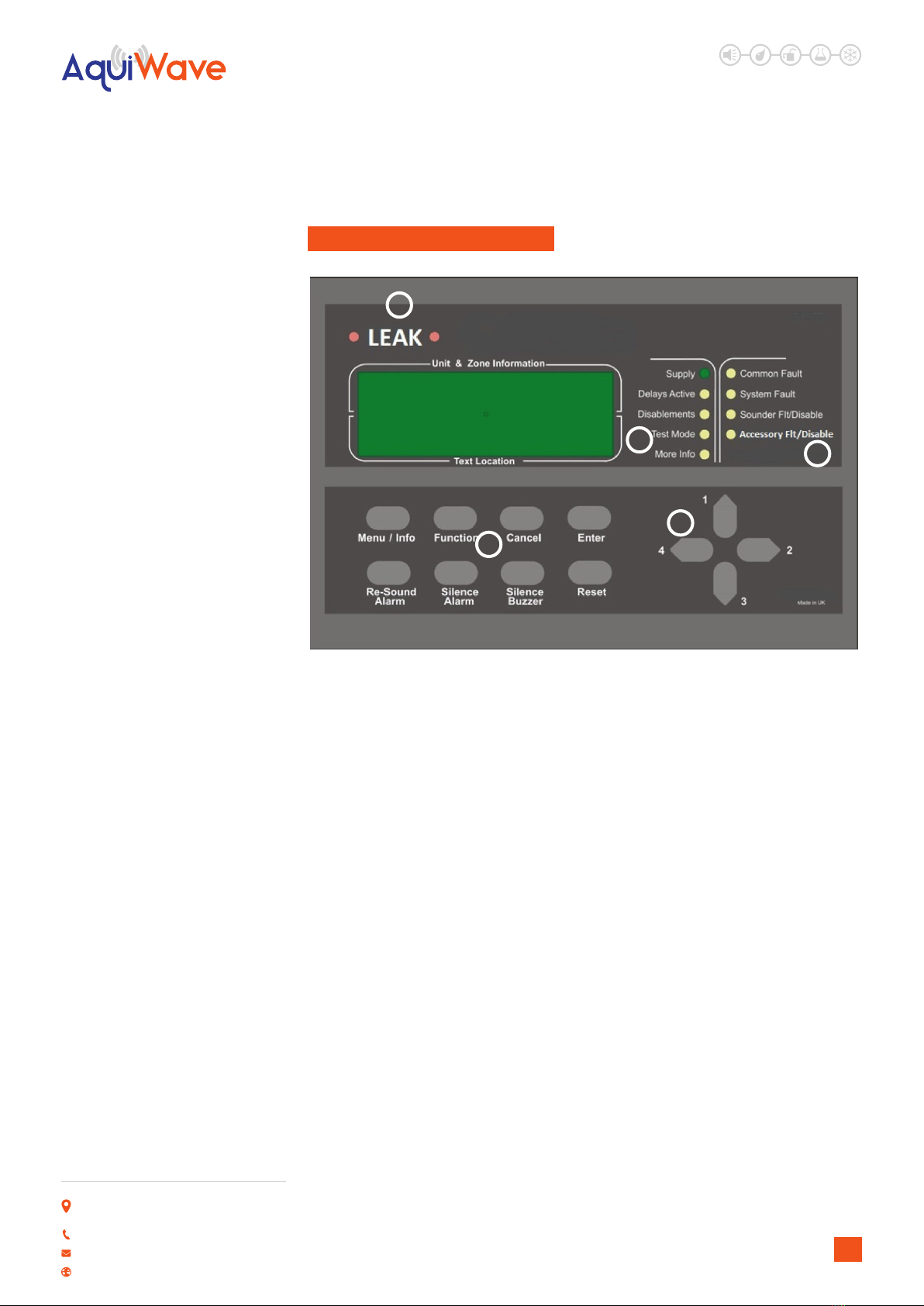
2.0 FRONT PANEL LAYOUT
1 LEAK LEDS
In a Leak condition, these LEDs will ash.
3 STATUS LEDS
Supply: This LED will be illuminated when
mains power is present.
Delays Active: Illuminated if delays are
enabled.
Disablements: Illuminated for any
disablement.
Test Mode: Illuminated if any test modes are
operational.
More Info: More information on the system
condition is available in the event log.
4 FAULT LEDS
Common Fault: Device or panel has a fault.
See main display for details.
System Fault: Fault that aects system
performance. See main display for details.
Sounder Flt/Disable: If the LED is ashing,
there is a fault with one or more sounders.
If the LED is solid, the sounders have been
disabled.
5 KEYS
Menu/Info: Press to initiate the menu
system. If held down for longer than 2
seconds, the LEDs will follow a test sequence
(lamp test).
Function: This button is disabled by default,
though it can be programmed to do a
number of functions. See 5.7 – User Options.
Cancel: Used to return to the main screen
from a menu or to return to the menu from a
programming screen.
Enter: This is used to accept information
programmed into the panel.
Re-sound Alarm: Following an alarm
condition that has been silenced, this button
will re-sound the alarm.
Silence Alarm: If the panel is in a leak
condition this will silence the sounders.
Silence Buzzer: Silences the panel buzzer for
all currently displayed faults or alarms.
Reset: Resets the panel from an alarm or
fault condition. Note that the system must be
silenced before it can be reset from a leak
condition.
1
34
5
6
10
LEAK DETECTION SOLUTIONS
Weights & Measures House, 20 Barttelot Road,
Horsham, West Sussex RH12 1DQ
+44 (0) 1403 216100
www.aquilar.co.uk
AquiWave
Wireless Leak
Detection System
6 NAVIGATION KEYS
Use to navigate through the menu structure
and programming/status screens. In a
multiple fault or alarm condition, the up and
down arrow keys allow the user to scroll
through all the current events. The display
will also scroll automatically every 4 seconds.
The navigation keys are numbered 1 to 4.
This is to allow the user to enter a 4 digit
access code when prompted.
3.0 USER OPERATION
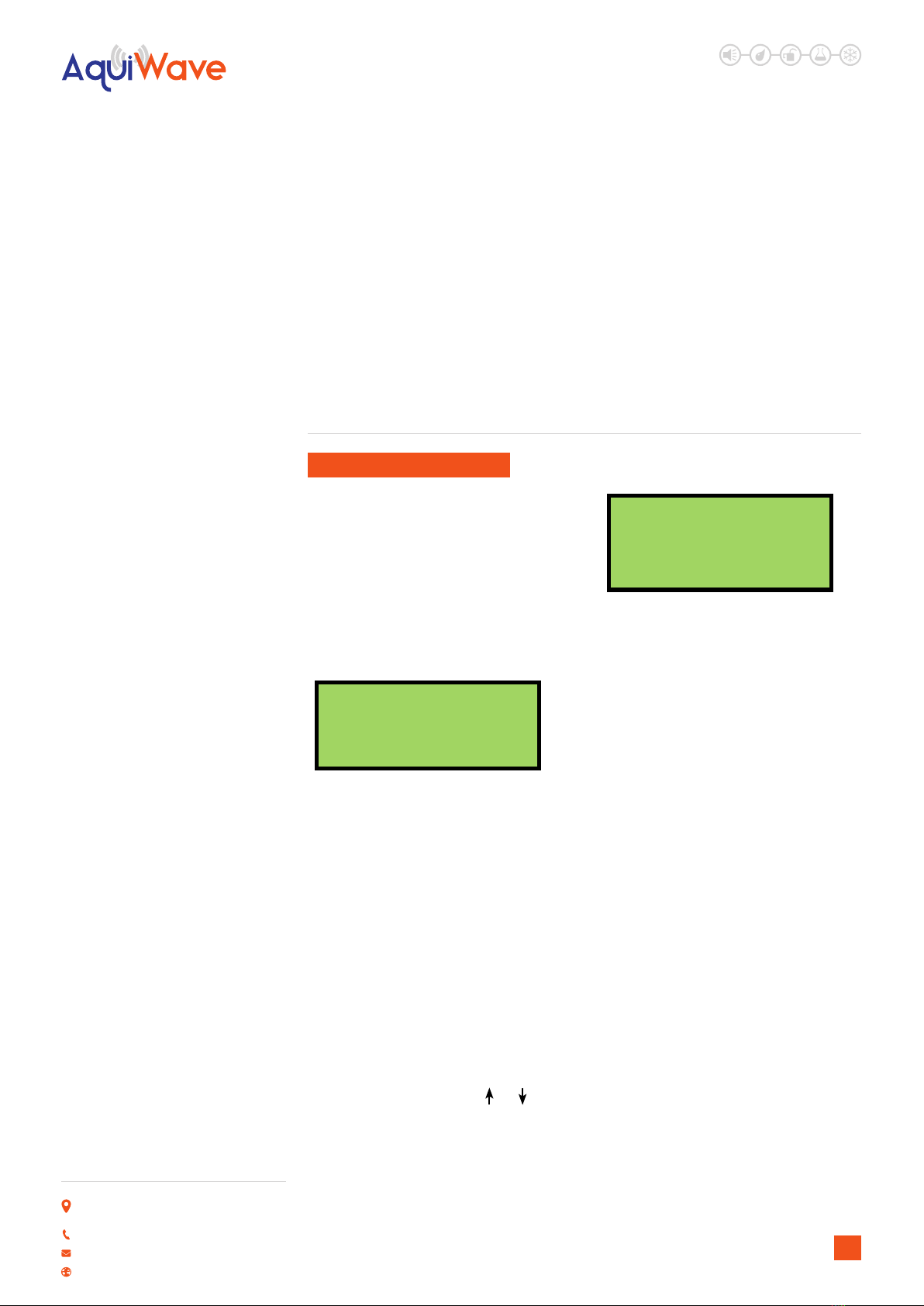
3.1 SYSTEM NORMAL
In normal operation the screen will show
either the date and time, or the supplier/
service contact details. The unit can also be
congured to alternate between the two. If
congured this way, the display will change
every 4 seconds. See 5.4 – Programming
Agent Details. Also a single green ‘Supply’
LED will be illuminated.
Tuesday
01-01-2013
12:04:36
3.2 FAULT CONDITIONS
If a fault occurs, the internal buzzer will sound
and a message will be displayed. The rst line
details the current fault number, the zone
and the type of fault. The second line details
the device type and the device number. The
third and fourth lines display the device
location text (if programmed). The description
has a maximum length of 40 characters
across 2 lines. Appropriate action should be
taken to remedy the fault as this may aect
the operation of the leak alarm system. If in
doubt, the system maintenance company
should be contacted. If more than one fault
exists on the system they will scroll round
every 5 seconds. Pressing the or cursor
key will display the next or previous fault.
001 Zn:001 VFY FAULT
Leak Detection TX
001
Entrance Hall
3.3 SILENT BUZZER
If the panel buzzer is sounding following a
fault or alarm, it can be silenced with the
Silence Buzzer key. Once the Silence Buzzer
button has been pressed the panel assumes
that the fault has been acknowledged and
does not re-sound the buzzer, unless a
new fault occurs. The LED on the device will
continue to ash until the fault is reset – see
below.
3.4 RESET A FAULT
A fault will be displayed on the panel until
the system is reset, even if the fault condition
has been rectied. Assuming the fault has
been rectied; pressing Reset on the panel
will reset the panel and the devices on which
the fault has occurred. The system normal
screen will then be displayed. If the fault
is still present or re-occurs, it will be re-
displayed. Where there are multiple faults,
all will be reset at the same time. It is not
necessary to silence a fault before resetting
it. The particular device or devices in fault will
also ash a green LED and beep. The system
silence and reset function can be protected
with an access code by turning on ‘Code
Protect’; see 5.8 – System Options.
11
LEAK DETECTION SOLUTIONS
Weights & Measures House, 20 Barttelot Road,
Horsham, West Sussex RH12 1DQ
+44 (0) 1403 216100
www.aquilar.co.uk
AquiWave
Wireless Leak
Detection System
Resetting
Please Wait
3.5 ALARM CONDITIONS
In a leak Alarm condition, a screen similar to
this will be displayed. The leak LEDs will ash.
Assuming the system is programmed to do
so, the leak relays will be activated. The rst
line of the display shows the event number
and the zone number. The second line details
the device type and its number. If the device
location has been programmed into the
panel, it will be displayed on the third and
fourth lines. Scroll through multiple alarms
using the and keys.
001 Zone 001
Leak Detection TX
001
Conference Room
3.6 SILENCE THE ALARM
Only when the leak or fault has been
investigated should the Silence Alarm button
be pressed. The system silence and reset
function can be protected by an access code
by turning on ‘Code Protect’; see 5.8 – System
Options.
3.7 RE-SOUND THE SOUNDERS
There may be times when the sounders have
been mistakenly silenced – for example if the
alarm was genuine but someone pressed
silence. The Re-Sound Alarm button followed
by a valid access code will activate the
sounders again.
3.8 RESET THE ALARM
Assuming the reason for the alarm condition
has been investigated; pressing Reset after
silencing the alarm will return the system
to its normal operation screen and reset
the devices that prompted the alarm. The
system silence and reset function can be
protected by an access code by turning on
‘Code Protect’; see 5.8 – System Options.
If code protect is enabled the user will be
prompted to enter a valid access code using
the navigation keys before being able to reset
the system.
If a device has remained in alarm (i.e. the leak
has not been cleared/dried, or fault rectied)
after silencing the alarm and pressing Reset,
the panel will redisplay the alarm and go back
into an ‘alarm state’.
3.9 ACCESS LEVELS
The panel is protected from misuse by means
of four access levels. The access levels are as
follows:
Level 1: Untrained user
Level 2A: Basic user
Level 2B: Advanced user
Level 3A: Service and Maintenance Engineer
Level 3B: Commissioning Engineer
Level 4: Manufacturer – Access tools required
Enter Access Code
----
A Level 1 untrained user can view the current
system state including any faults, alarms,
disablements and tests. They can also silence
and reset alarms unless code protection has
been enabled. See 5.1 – Quick Menu.
A Level 2A basic user can view the current
operational condition of the system, access
the disable/enable menu and may silence
and reset alarms with code protection active.
A Level 2B advanced user in addition has
access to test mode and the event log.
A Level 3A engineer in addition has access to
system and device information and the verify
table.
A Level 3B commissioning engineer has
access to all system options, including
programming and conguration of devices
and hardware.
12

LEAK DETECTION SOLUTIONS
Weights & Measures House, 20 Barttelot Road,
Horsham, West Sussex RH12 1DQ
+44 (0) 1403 216100
www.aquilar.co.uk
AquiWave
Wireless Leak
Detection System
All menus, settings and options described in
this manual show the required access level in
the title. For example: 7.4 - Enable System Test
– service and commissioning users
Each access level (excluding level 1) requires
a 4 digit code to access the menus. See 5.2 –
View Access Codes.
4.0 MENU OPERATION
To enter the menu system, press Menu.
This will display an overview of any alarms,
faults, disablements or tests that are
currently active, along with an option to
access the Main Menu. The options available
on the main menu and sub-menus will be
dependent on the access code entered and
its corresponding access level. To scroll
through the menu the and keys should
be pressed. In order to select a menu option
the key should be pressed. To return to
the previous menu screen from a sub-menu
the key should be pressed. Pressing
Cancel will return to the system screen
where any faults or alarms will be displayed
if present.
For every menu option listed in this manual,
its place in the menu structure will be shown
in grey text underneath the heading. For
example, the event log can be found by
selecting the ‘Main Menu’, followed by ‘View
Events’ and selecting ‘View Event Log’.
1.Main Menu>>4.View Events>>2.View Event
Log
If a non-menu screen is selected the Cancel
button should be pressed to return to
the menu without making any changes.
Subsequently, then pressing Cancel for
a second time will return to the system
screen. If any changes are made to settings,
these are generally saved using the Enter
key as detailed on the display. If an alarm
occurs while in menu mode, the menu will
be automatically cancelled, and the alarm
message displayed. If a fault occurs while in
the menu mode, the fault LED will light but
the display will remain in the menu mode
until cancelled in the usual way.
4.1 QUICK MENU – ALL ACCESS
LEVELS
Pressing Menu once will display the Quick
Menu. Navigate using the cursor keys. Any
active alarms, faults, disablements or tests
will be displayed. No access code is needed
to view the events listed. You will only be
prompted to enter an access code if you
select ‘1-Main Menu’.
1>Main Menu
2 Alarms(000)
3 Faults(002)
4 Disablements(000)
When a category (e.g. Faults) is selected, the
rst screen will display information such as
the device number, zone, type of fault and
any text location.
001 Zn:001 SHORT CCT
CONTROL IP1
13

LEAK DETECTION SOLUTIONS
Weights & Measures House, 20 Barttelot Road,
Horsham, West Sussex RH12 1DQ
+44 (0) 1403 216100
www.aquilar.co.uk
AquiWave
Wireless Leak
Detection System
Pressing the key will display the time and
date that the event happened.
Time:12:00:08
Date:25/06/13
5.0 SETUP MENU
5.1 CHANGING THE SYSTEM TIME
AND DATE – ALL ACCESS LEVELS
1. Main Menu>>1.Setup>>1.Time & Date
To change the time and date settings use the
and keys to navigate to the value, and
the or keys to select the desired value.
Press Enter to accept or Cancel to exit. The
AquiWave panel automatically adjusts the
clock for daylight savings. Should complete
power be lost the panel will revert the time
back to the default of 01/01/2013 12:00:00
Time: 12:39:00
Date: 01-01-2013
ENTER to save
5.2 - VIEW ACCESS CODES
– ADVANCED, SERVICE AND
COMMISSIONING USERS
1. Main Menu>>1.Setup>>2.Access Codes>>1.
View Codes
The access code is a 4 digit number; with
each digit ranging from 1 to 4. Selecting ‘1-
View Codes’ will display the screen opposite.
Only access codes for the access level you
have entered and those below it will be
displayed.
AL1 1111 AL2 2222
CANCEL to exit
CHANGING ACCESS CODES
– ADVANCED, SERVICE AND
COMMISSIONING USERS
1. Main Menu>>1.Setup>>2.Access Codes>>2.
Change Codes
Using the cursor keys select the access level
for which the access code is to be changed.
Users can only change the access code for
their level and below. Once selected, press
the key to continue. Using the numbered
keys enter the current access code.
Enter Current Code
----
CANCEL to exit
If correct, you will be prompted to enter your
chosen new access code, then to re-enter
it to conrm. Press Enter to save the new
access code, a message will be displayed
that the access code is being saved. Press
Cancel to exit without saving at any time.
Enter New Code
----
CANCEL to exit
SET ACCESS CODES TO DEFAULT –
COMMISSIONING USERS
1.Main Menu>>1.Setup>>2.Access Codes>>3.
Set to Default
Use this option to reset the user access
codes to their default settings. Press Enter to
conrm.
14
LEAK DETECTION SOLUTIONS
Weights & Measures House, 20 Barttelot Road,
Horsham, West Sussex RH12 1DQ
+44 (0) 1403 216100
www.aquilar.co.uk
AquiWave
Wireless Leak
Detection System
5.3 - DEFAULT ACCESS CODES
Basic User (AL2A): 1111
Advanced User (AL2B): 2222
Service Engineer (AL3A): 3333
Commissioning Engineer (AL3B): 4444
AL2A 1111 AL2B 2222
AL3A 3333 AL3B 4444
CANCEL to exit
Note: Ensure that the access codes AL3A
& AL3B are changed from the default
settings to ensure that only authorised
personnel can make changes to the
system
5.4 - PROGRAMMING AGENT DETAILS
– SERVICE AND COMMISSIONING
USERS
1.Main Menu>>1.Setup>>3.Panel Display
The system normal screen can be adjusted to
display either the date and time, the agent’s
name and telephone number or alternating
between the two every 4 seconds. In order to
display the agent’s details, they will need to
be programmed into the panel. 20 characters
per line can be programmed.
Tuesday
01-01-2013
12:04:36
Text can be programmed into the control
panel using a USB keyboard or via the panel
buttons. From the ‘Panel Display’ menu select
‘1-Agent Name’. Enter text then press Enter to
save. Select ‘2-Agent Phone’. Enter text then
press Enter to save. If entering text via the
panel use the key to display the characters.
Browse the characters using the
keys; select the highlighted character using
the . Menu key is SPACE and Function is a
BACKSPACE. Once complete press to hide
the characters and press . Conrm the
text is correct and press Enter to save. To
return to the menu press Cancel.
A.N Other Firm
01403 216100
12:04:36
CHANGE DISPLAY OPTIONS –
SERVICE AND COMMISSIONING
USERS
1.Main Menu>>1.Setup>>3.Panel Display>>3.
Display Options
Using the or keys, select ‘Time/Date’,
‘Agent Details’ or ‘Alternating’. Press to
select the option. Press Enter to save.
Alternating
Use keys
5.5 - PANEL INFORMATION
1.Main Menu>>1.Setup>>4.System Setup>>1.
Panel Info
It is possible to view information regarding
the panel, such as the software version,
system number and the number of devices
programmed onto the system.
PANEL STATUS – SERVICE AND
COMMISSIONING USERS
1.Main Menu>>1.Setup>>4.System Setup>>1.
Panel Info>>1.Status
Using the or keys, select ‘Time/Date’, ‘Agent
Details’ or ‘Alternating’. Press to select the
option. Press Enter to save.
Sys No:00699
Devices:001
Use key
Panel No:01/01
Antennas:01
Use keys
15

LEAK DETECTION SOLUTIONS
Weights & Measures House, 20 Barttelot Road,
Horsham, West Sussex RH12 1DQ
+44 (0) 1403 216100
www.aquilar.co.uk
AquiWave
Wireless Leak
Detection System
Ver:01.00 20Mar13
Uptime:0000d 03h 13m
Use key
TxRx
Version:01.02
Uptime:0000d03h13m45
Use key
Display
Version:01.01
Uptime:0000d04h16m33
Use key
Sys No: System number.
Devices: Number of devices added to the
panel.
Panel No: Panel number and last panel
number on system.
Antennas: Number of antennas assigned to
the panel.
Ver: Software version.
Uptime: Operational time since panel was
last powered down.
PANEL READINGS – SERVICE AND
COMMISSIONING USERS
1.Main Menu>>1.Setup>>4.System Setup>>1.
Panel Info>>2.Panel Readings
IP1: The resistance level on input 1.
IP2: The resistance level on input 2.
OP1: The resistance level on output 1.
OP2: The resistance level on output 2.
OP3: The resistance level on output 3.
OP4: The resistance level on output 4.
Vbus: The voltage of the PSU.
Light: Light sensor voltage
IP1:4535 IP2:4513
OP1:4579 OP2:>10K
OP3:4528 OP4:4671
01314 01862
Vbus:14.9
Light:00.00V
Use key
VIEW ANTENNA INFORMATION –
SERVICE AND COMMISSIONING
USERS
1.Main Menu>>1.Setup>>4.System Setup>>1.
Panel Info>>3.Antenna Info
Ant: The currently selected antenna.
Sys: The system number programmed
at the antenna.
RSSI: Received signal strength indicator,
from -20 to +20.
RF Chan: The channel the system is using.
Pan: The number of the panel
programmed at the antenna.
Slot: Device protocol slot.
Squelch: RF interference lter. Non-user
adjustable.
Ant:01 Sys:00699
RSSI:20
RF Chan:09 Pan:01
Slot:195 Sqlch:100
VIEW PAGER INFORMATION –
SERVICE AND COMMISSIONING
USERS
1.Main Menu>>1.Setup>>4.System Setup>>1.
Panel Info>>4.Pager Info
This menu displays information for any alert
pagers that have been set up on the system.
VIEW POWER SUPPLY INFORMATION
– SERVICE AND COMMISSIONING
USERS
1.Main Menu>>1.Setup>>4.System Setup>>1.
Panel Info>>5.PSU Info
Vin: Input Voltage.
Vbus: The voltage of the PSU.
Vbat: The voltage of the battery.
Ib: Battery current.
16
LEAK DETECTION SOLUTIONS
Weights & Measures House, 20 Barttelot Road,
Horsham, West Sussex RH12 1DQ
+44 (0) 1403 216100
www.aquilar.co.uk
AquiWave
Wireless Leak
Detection System
Io: PSU output current.
Status: PSU fault status.
State: PSU state.
PWM: Duty cycle.
Temp: PSU temperature (oC).
Version: The rmware version of the power
supply PCB.
Uptime: Operational time since PSU was last
powered down.
5.6 - SET UP A NEW SYSTEM
(STANDARD) – COMMISSIONING
USERS
1.Main Menu>>1.Setup>>4.System Setup>>2.
New Setup>>1.Standard System
Devices are programmed via a radio link to
the control panel. If the system is known to
have been used before then all the devices
that are logged on to the system must be
removed rst. To add or remove devices on a
system that is already set up; see 5.26 – Add
Device and 5.27 – Remove Device.
System Setup
ENTER to continue
Press Enter to start. You will be asked if you
would like to put the system into test mode
(see 7.0 – Test Mode). Select YES or NO and
press Enter. The control panel will now check
the airwaves for any radio interference and
select a suitable channel for the system. Press
Enter to continue. Select the antenna type. At
the Device Programming screen, the device
needs to be put into programming mode.
First remove the device from its base.
1. If a leak detection TX is being
programmed; hold the reset button
down while you place the jumper link to
the ON position
2. If a sounder, beacon, transmitter or I/O
unit is being programmed; hold down
the unit removal button while holding a
magnet over the reed switch and place
the jumper link to the ON position.
Some newer devices are equipped with
a log on button and do not require the
magnet to log on; simply hold down the
button while the jumper link is moved to
the ON position.
System will test
radio channel
ENTER to continue
Channel 09
RSSI -20
/
Please wait
Continue to hold the button(s) for
approximately 5 seconds until a conrmation
of 3 beeps from the device is heard. The LED
on the device will now ash green. The device
is now in its programming mode. Press Enter
on the panel to search for the device and
follow the prompts to set the device options.
When complete press Enter to program the
device.
Device Programming
ENTER to continue
Device Found
Leak Detection TX
Use keys
Once the device has restarted you will be
asked to enter location text; see 5.30 –
Device Text. Text can be added at any time.
Devices can be added at any time in the
Device Setup menu.
If the system has booster panels or additional
antennas tted, an auto assignment for
all devices should be performed once all
devices have been added. See 5.17 – Device
Assignment.
17

LEAK DETECTION SOLUTIONS
Weights & Measures House, 20 Barttelot Road,
Horsham, West Sussex RH12 1DQ
+44 (0) 1403 216100
www.aquilar.co.uk
AquiWave
Wireless Leak
Detection System
5.7 - USER OPTIONS – COMMISSIONING USERS
1.Main Menu>>1.Setup>>4.System Setup>>3.Edit Panel>>1.Panel Options>>1.User Options
Detailed below are the other options that can be changed related to the panel. The default
settings are strongly recommended. Selecting some of the available options may result
in a system which may not provide suitable protection. If unsure, contact Aquilar or your
installation/service representative for advice.
Panel Zone The zone the panel is located in.
Func Key Set the function key as disabled, evacuate, alert or delay toggle.
Default settingis - disabled
Func Tone The tone to be sounded if the function key is pressed and has been
programmed as either evacuate or alert.
Func Relay The relay to be operated if the function key is pressed and has been
programmed as either evacuate or alert.
Double Knock Whether double knock is enabled. See 13.0 – Delays.
Double Knock Tone The tone to be sounded after second device activates.
Double Knock Relay The relay to be operated after second device activates.
Double Knock Zone Whether a second device in the same zone or any second device
operates the double knock.
Relay 1 Type Choose relay type 0 to 5. Default setting is 2. Fault relay is default.
Relay 1 Reset Whether Relay 1 is cleared upon pressing silence or upon pressing
reset.
Relay 2 Type Choose relay type 0 to 5. Default setting is 4. Failsafe fault relay is
default.
Relay 2 Reset Whether Relay 2 is cleared upon pressing silence or upon pressing
reset.
Relay 3 Type Choose relay type 0 to 5. Default setting is 1. Leak Relay is default.
Relay 3 Reset Whether Relay 3 is cleared upon pressing silence or upon pressing
reset.
Relay 4 Type Choose relay type 0 to 5. Default setting is 1. Leak Relay is default.
Relay 4 Reset Whether Relay 4 is cleared upon pressing silence or upon pressing
reset.
Relay1 Type 1
Leak Relay
Use keys
The relay types are listed below:
Type 0 Disabled
Type 1 Leak Relay
Type 2 Fault Relay
Type 3 Sounder Circuit
Type 4 Fault Relay Safe
Type 5 Accessory Circuit
IMPORTANT!: The relay types are congured not only in the panel software but also by
physically placing jumper links on the panel PCB. Refer to page 8/9 for relay link positions
and fuse requirements.
18

LEAK DETECTION SOLUTIONS
Weights & Measures House, 20 Barttelot Road,
Horsham, West Sussex RH12 1DQ
+44 (0) 1403 216100
www.aquilar.co.uk
AquiWave
Wireless Leak
Detection System
5.8 - SYSTEM OPTIONS – COMMISSIONING USERS
1.Main Menu>>1.Setup>>4.System Setup>>3.Edit Panel>>1.Panel Options>>2.System Options
This menu allows the user to change overall system settings.
Alarm Verify Time (seconds) that a device has to be in alarm to generate an alarm
condition on the panel.
Antenna Type Specify if the main panel is using a Stub (6775), Dipole (6745) or
Intelligent antenna (6740).
Code Protect Whether an access code is needed to silence or reset an alarm or
fault. Default is set to OFF.
Sil Alm Delay Length of time (seconds) the ‘Silencing – Please Wait’ screen is
displayed.
Res Alarm Delay Delay between pressing the reset button and the system resetting
an alarm condition.
Res Flt Delay Delay between pressing the reset button and the system resetting a
fault condition.
Auto Resound When set to By Zone; if an alarm condition has been silenced and
another device goes into alarm, the sounders will only start sounding
again if the device is in a dierent zone. When set to By Device; if an
alarm condition has been silenced, any other device which goes into
alarm will cause the sounders to start sounding again.
5.9 - FAULT OPTIONS – COMMISSIONING USERS
1.Main Menu>>1.Setup>>4.System Setup>>3.Edit Panel>>1.Panel Options>>3.Fault Options
This menu allows the user to enable or disable certain types of faults, and to change the
levels or time periods required to produce a fault condition. The default settings are strongly
recommended. Selecting some of the available options may result in a system which may not
provide suitable protection. If unsure, contact your installer or Aquilar for advice.
Verify Time Time without communication from a particular device before the
system generates a verify fault. The default is 390 seconds.
Show Batt Low Enable or disable faults for low battery alerts from devices.
Batt Low T/out If disabled, the time period until faults for low battery automatically
re-enable.
Show Int Fail Enable or disable faults for internal failures from devices.
Int Fail T/out If disabled, the time period until faults for internal failures
automatically reenable.
Interference The level of interference required for the panel to generate an
interference warning. This is set to o by default.
Interference Period The minimum length of the interference required for the panel to
generate an interference warning.
Show Batt Warning Enable or disable warning messages for low panel battery.
19
This manual suits for next models
1
Table of contents
Other aquilar Measuring Instrument manuals


Popular Measuring Instrument manuals by other brands


Rover Instruments
Rover Instruments CNG 90 user guide

Nelson-Jameson
Nelson-Jameson 926S Operator's manual

Emerson
Emerson Daniel 3410 Series Maintenance and troubleshooting manual

Preventice Solutions
Preventice Solutions ER920W Patient Instruction Manual

KAM
KAM Simple Precision PKF user manual

AEMC instruments
AEMC instruments Simple Logger AmpFlex AL24-2500 user manual