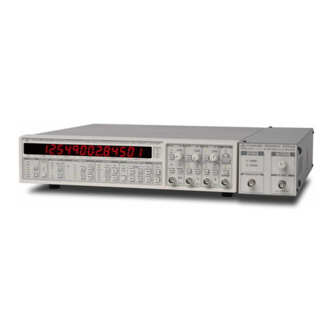
SRS Labs SR715 User manual

User’s Manual
Model SR715
Model SR720
LCR Meters
1290-D Reamwood Avenue
Sunnyvale, California 94089
Phone: (408) 744-9040 • Fax: (408) 744-9049
Copyright © 1991 by SRS, Inc.
All Rights Reserved.
Revision 1.5 (09/2001)

TABLE OF CONTENTS
i
GENERAL INFORMATION
Safety and Preparation for Use iii
Specifications v
Basic Operation viii
Passive Devices viii
Series and Parallel Circuit Models ix
Typical Measurement Setups x
How the SR715/720 Works xi
Abridged Command List xii
Status Bytes xiii
GETTING STARTED
SR715/720 1-1
Display 1-2
Keypad 1-3
Fixture 1-5
Rear Panel 1-6
OPERATION
Display 2-1
Displayed Parameters 2-1
Series & Parallel Equivalent Circuits 2-2
Display Types 2-2
Status & Binning 2-3
Test Conditions 2-4
Default Conditions 2-4
Setting Test Conditions 2-4
Frequency 2-4
Output Voltage 2-4
Range 2-6
Autoranging 2-6
Range Hold 2-6
Constant Voltage 2-7
Bias 2-8
Internal Bias 2-8
External Bias 2-9
Measurement Rate 2-9
Settling Time 2-10
Triggering 2-10
Store and Recall 2-11
Connecting a Device 2-12
Radial Leaded Parts 2-12
Axial Leaded Parts 2-12
Component Dimensions 2-13
Optional Fixtures 2-13
Fixture Adapter 2-13
Kelvin Clips 2-14
SMD Tweezers 2-14
BNC Adapter 2-15
Open & Short Calibration 2-16
Suggestions for Calibration 2-16
Radial Fixture 2-16
Axial Fixture Adapter 2-16
Kelvin Clips 2-16
SMD Tweezers 2-17
Other Fixtures 2-17
Binning 2-18
Setting Up the Bins 2-19
Examples 2-20
Binning Worksheet 2-21
Option 01: GPIB Handler Interface 2-22
ACCURACY
Conditions 3-1
Impedance Accuracy 3-2
R+Q Accuracy 3-4
L+Q Accuracy 3-5
C+D Accuracy 3-6
C+R Accuracy 3-7
Accuracy With Range Hold 3-8
PROGRAMMING
GPIB Communications 4-1
RS232 Communications 4-1
Front Panel LEDs 4-1
Command Syntax 4-1
Programming Errors 4-2
No Command Bit 4-2
Detailed Command List 4-3
Measurement Setup Commands 4-3
Measurement Control Commands 4-4
Measurement Result Commands 4-4
Binning Commands 4-6
Setup & Control Commands 4-7
Status Reporting Commands 4-7
Test & Calibration Commands 4-8
Status Byte Definitions
Serial Poll Status Byte 4-10
Standard Event Status Byte 4-11
LCR Status Byte 4-11
Program Examples
Microsoft C, Nat'l Instruments GPIB 4-12
Microsoft C, CEC GPIB 4-14
Binning 4-17
IBM BASIC, RS232 4-21
TESTS and CALIBRATION
Functional Tests 5-1
Front Panel Test 5-1
Self Test 5-2

TABLE OF CONTENTS
ii
Output Voltage 5-2
Resistance Measurement 5-2
Capacitance Measurement 5-2
Performance Tests 5-4
Frequency Accuracy 5-4
Amplitude Accuracy 5-5
Impedance Accuracy 5-5
Resistance Accuracy 5-5
Capacitance Accuracy 5-6
Performance Test Record 5-8
Calibration 5-10
Introduction 5-10
Calibration Enable 5-10
Calbytes 5-10
Amplitude Calbytes 5-11
Floating Point Calbytes 5-11
Amplitude Calibration 5-12
Frequency Calibration 5-13
Standard Resistor Calibration 5-13
TROUBLESHOOTING and
MAINTENANCE
Nothing Happens at Turn On 6-1
Reset 6-1
Internal Fuse 6-1
External Bias Fuse 6-1
Error Messages 6-2
Operations Errors 6-2
Self-test Errors 6-2
Calibration Errors 6-4
GPIB Problems 6-4
RS232 Problems 6-4
Fixture Maintenance 6-5
Cleaning 6-5
Removing Leads 6-5
Changing Radial Contacts 6-5
SMD Tweezer Maintenance 6-7
Cleaning 6-7
Tip Replacement 6-7
PARTS and SCHEMATICS
Parts List 7-1
Schematic Diagrams 7-13

SR715/720 LCR METER
iii
SAFETY AND PREPARATION FOR USE
WARNING
Dangerous voltages, capable of causing injury or death, are present in this instrument. Use extreme caution
whenever the instrument cover is removed. Do not remove the cover while the unit is plugged into a live outlet.
CAUTION
This instrument may be damaged if operated with
the LINE VOLTAGE SELECTOR set for the wrong
AC line voltage or if the wrong fuse is installed.
LINE VOLTAGE SELECTION
The SR715/720 operates from a 100V, 120V,
220V, or 240V nominal AC power source having a
line frequency of 50 or 60 Hz. Before connecting
the power cord to a power source, verify that the
LINE VOLTAGE SELECTOR card, located in the
rear panel fuse holder, is set so that the correct AC
input voltage value is visible.
Conversion to other AC input voltages requires a
change in the fuse holder voltage card position and
fuse value. Disconnect the power cord, open the
fuse holder cover door and rotate the fuse-pull
lever to remove the fuse. Remove the small
printed circuit board and select the operating
voltage by orienting the printed circuit board so that
the desired voltage is visible when pushed firmly
into its slot. Rotate the fuse-pull lever back into its
normal position and insert the correct fuse into the
fuse holder.
LINE FUSE
Verify that the correct line fuse is installed before
connecting the line cord. For 100V/120V, use a 1/2
Amp fuse and for 220V/240V, use a 1/4 Amp fuse.
LINE CORD
The SR715/720 has a detachable, three-wire
power cord for connection to the power source and
to a protective ground. The exposed metal parts of
the instrument are connected to the outlet ground
to protect against electrical shock. Always use an
outlet which has a properly connected protective
ground.
BIAS VOLTAGE ON CAPACITORS
Verify that polarized capacitors are installed with
the correct polarity before applying a bias voltage.
Failure to do so can result in damage to the unit,
the device under test, or possible injury. The
SR715/720 fixture and remote fixtures are marked
with '+' and '-' signs, or by red leads for the positive
connectors. Capacitors charged by an external
bias voltage should be discharged after making the
measurement. A 40 volt external bias can charge a
capacitor to a high enough voltage that it can
cause injury if it is accidentally discharged. See the
section on BIAS for more information on how to
safely apply external bias voltage.
When connecting the external bias voltage to the
unit, observe the correct polarity and make certain
that the bias supply is floating (neither side is
connected to ground). Be certain to use a supply
current limited to 250 mA or less.
PROTECTION FUSES
In addition to the line fuse, the SR715/720 has two
other protection fuses. The external bias fuse
(3AG 0.25 A) is installed on the rear panel, next to
the bias terminals. If unstable readings occur when
making measurements with an external bias,
check this fuse. The other fuse is an output
protection fuse (2AG 0.25 A) located internally on
the main PCB. If unstable or erratic readings occur
or an 'outPut Err' (output err) occurs during self
test, this fuse may be damaged. See the
maintenance section for more information.
SERVICE
Do not attempt to service or adjust this instrument
unless another person, capable of providing first
aid or resuscitation, is present. Do not install
substitute parts or perform any unauthorized
modifications to this instrument. Contact the
factory for instructions on how to return the
instrument for authorized service and adjustment.

SR715/720 LCR METER
iv

SR715/720 LCR METER
v
GENERAL INFORMATION
The SR715/720 LCR Meters are multifrequency impedance measuring instruments, capable of measuring
resistance, capacitance or inductance over a range of more than 13 orders of magnitude. The SR720 has a
basic accuracy of 0.05% and has 5 test frequencies. The SR715 has a basic accuracy of 0.2% and 4 test
frequencies.
The LCR meters are controlled by a high speed microcontroller that operates the display, keypad, RS232 and
GPIB computer interfaces, and handler interface, as well as setting measurement conditions and performing
calculations. In addition, non-volatile storage is provided for 9 complete instrument settings.
SPECIFICATIONS
DISPLAY
Measurement Modes Auto, R+Q, L+Q, C+D, C+R
Equivalent Circuit Series or Parallel
Parameters Displayed Value, Deviation, % Deviation or Bin Number.
Deviation and % deviation are calculated from a stored relative value.
Averaging 2 - 10 Measurements
Measurement Range R+Q: R 0.0001 Ω- 2000 MΩ
Q 0.00001 - 50
L+Q: L 0.0001 µH - 99999 H
Q 0.00001 - 50
C+D: C 0.0001 pF - 99999 µF
D .00001 -10
C+R: C 0.0001 pF - 99999 µF
R .00001 - 99999 kΩ
TEST CONDITIONS
Test Frequency 100 Hz, 120 Hz, 1 kHz, 10 kHz, 100 kHz (100 kHz - SR720 only).
Frequency accurate to ±100ppm.
Drive Voltage Preset Levels: 0.10, 0.25, and 1.0 Vrms.
Vernier: 0.1 to 1.0 Vrms with 50 mV resolution.
Drive levels accuracy ±2%.
Measurement Rate Slow, Medium, Fast: 2, 10, or 20 measurements per second at test
frequencies of 1 kHz and above and about 0.6, 2.4, or 6 measurements per
second at 100 Hz and 120 Hz.
Ranging Auto or Manual
Triggering Continuous, Manual, or Remote over RS232, GPIB or Handler Interface
Bias Voltage Internal: 2.0 VDC ±2%
External : 0 to +40 VDC (fused @ 0.25 A)

SR715/720 LCR METER
vi
ACCURACY
Conditions At least 30 minute warm up, 23 °C ± 5 °C.
Basic Accuracy SR715: 0.20%
SR720: 0.05%
See the Accuracy section for detailed accuracy specifications.
The table below summarizes the typical use accuracy.
Accuracy SR720 SR715
better than 1% 0.125 Ω< R < 16 MΩ0.143 Ω< R < 14 MΩ
2.5 µH < L < 25 kH 2.9 µH < L < 22 kH
1.25 pF < C < 12.8 mF 1.43 pF < C < 11.2 mF
better than 5% 21 mΩ< R < 96 MΩ21 mΩ< R < 94 MΩ
420 nH < L < 150 kH 426 nH < L < 150 kH
0.21 pF < C < 77 mF 0.21 pF < C < 75 mF
The following conditions apply:
1) 1.0, 0.5 or 0.25 V output voltage
2) Slow or medium measurement speed
3) Q and D < 0.1 for R and C
4) Q > 10 for L
5) 100 Hz, 120 Hz or 1 kHz test frequency for R
6) 100 Hz test frequency for Lmax and Cmax
7) 10 kHz test frequency for Lmin and Cmin
FEATURES
Fixture 4-Wire Kelvin fixture for radial leaded parts with adapters for axial leaded
parts.
Protection Protected up to 1 Joule of stored energy, 200 VDC max (for charged
capacitors).
Fused at 0.25 A output current for biased measurement.
Zeroing Open and Short Circuit Compensation.
Compensation Limits Short: R < 20 Ω, Z < 50 Ω
Open: Z > 10 kΩ
Binning Up to 8 Pass Bins, QDR and General Fail Bins, all defined from the front
panel or over the computer interfaces. Binning setups may be stored in non-
volatile memory.
Self Test Tests the ROM, CPU, Non-Volatile RAM, Clock Generator, A/D Converter,
Internal Bias, Multiplier, Output Drive Circuitry, Gain Circuitry, and Source
Resistances.
Store and Recall Stores 9 Complete Instrument Setups. Recall 0 recalls Default Setup.
RS232 Interface All instrument functions can be controlled or read over the interface.
GENERAL
Operating Conditions 0 - 50 °C, <85% relative humidity.
Power 20 Watts, 100/120/220/240 VAC, 50 or 60 Hz.
Dimensions (W x H x L) 13.5" x 4" x 14" (343 x 102 x 356 mm)
Weight 10 lbs (4.55 kg)
Warranty One year parts and labor on materials and workmanship.

SR715/720 LCR METER
vii
OPTIONS
GPIB / Handler Interface Option 01 provides both an IEEE-488 interface and a Handler interface.
IEEE-488 Interface: All instrument functions can be controlled or read
over the interface.
Handler/Sorter Interface: DB25 male connector provides output lines
to indicate binning information and
instrument status and an input trigger line.
Output lines include 8 Pass Bins, QDR Fail
Bin, General Fail Bin, Busy, and Bin Data
Available. Output lines are Open Collector
and are rated to 40 volts. The trigger input is
negative edge triggered TTL and is
protected to +/- 15 Volts.
SR726 Kelvin Clips Provides connection to devices that are not easily accommodated in the
fixture. Polarity is indicated for biased measurements. Connects to
SR715/720 fixture.
SR727 SMD Tweezers Provides connection to Surface Mount Device parts. Polarity is indicated for
biased measurements. Connects to SR715/720 fixture.
SR728 BNC Fixture Adapter Provides a means to connect a remote fixture or other device to the
SR715/720. Connects to SR715/720 fixture and has four 1 meter BNC
cables. Polarity is indicated for biased measurements.

SR715/720 LCR METER
viii
BASIC OPERATION
This section is designed to help the user begin
making measurements with the SR715/720 LCR
meter and to familiarize them with some of its
features. For more information on the different
features, see the operations section.
To operate the SR715/720, first verify that the
correct line voltage has been selected on the
power entry module on the rear panel (See page
1-3). Verify that no parts are in the fixture; the
unit's self test routines will fail if any components
are in the test fixture. After connecting the line cord
to the power entry module, switch on the power
switch, located on the rear right hand side of the
unit. The unit will display the ROM version on the
left display and the serial number on the right
display for about 3 seconds. Next, the unit will
begin its self test procedure. If all tests are OK,
'tESt PASS' will be displayed. See the
Troubleshooting section if the self test fails. Press
[Recall] [0] [ENTER], to recall the default setup.
This will set the unit as follows:
Parameter AUTO
Frequency 1 kHz
Drive Voltage 1.0 Vrms
Bias OFF
Measurement Rate SLOW
Averaging OFF
Range Hold OFF
Equivalent Circuit SERIES
Display VALUE
Trigger Mode CONT
Binning OFF
At this point a part can be placed in the fixture and
measurements can be made. The unit will
automatically decide which type of component is in
the fixture (R, C or L), change to the correct range,
and display the part value with the correct units. If
any of the test conditions need to be changed for a
measurement, press the appropriate keys. Most
functions are easy to change, but if more
information is needed, see the operating section.
The SR715/720 comes with a built in fixture for
measuring radial leaded components, like most
capacitors, and adapters for measuring axial
leaded components, like most resistors. To
measure a radial leaded component, remove any
adapters and put one lead of the component in
each side of the fixture. To measure an axial
leaded component, first install the fixture adapters.
Put the adapters on in the middle of each side of
the fixture, and then slide them until they are
separated by the appropriate distance. Insert the
one lead of the component into each side of the
fixture.
After changing the fixture configuration, it is a good
idea to perform an open and short circuit
calibration. See the operation section for
instructions. If the component leads are
excessively dirty or are coated with wax, clean
them before inserting them in the fixture. The
fixture contacts will usually make contact through
coatings, but can eventually get gummed up.
If biased measurements are being made on
capacitors, be certain that the part is installed
with the correct polarity, as marked on the unit.
What is a passive device?
All non-ideal passive devices (resistors, inductors
and capacitors) can be modeled as a real
component (resistor) either in series or in parallel
with a reactive component (capacitance or
inductance). The impedance of these components
change as a function of frequency. The series and
parallel models are mathematically equivalent and
can be transformed back and forth with the
equations shown below.
Usually one model is a better representation of the
device under operating conditions. The most
accurate model depends on the device and the
operating frequency. Certain devices are tested
under conditions defined by the manufacturer or
industry standard. For example, electrolytic
capacitors are often measured in series at 120 Hz
in the C+R mode, so the ESR (equivalent series
resistance) can be measured.

SR715/720 LCR METER
ix
Series and Parallel circuit models
Rs in capacitors is often referred to as ESR or
equivalent series resistance. It includes things like
dielectric absorption in addition to the ohmic losses
due to the leads. It is often listed on data sheets
for electrolytic capacitors used in switching power
supplies. At high frequencies, the ESR is the
limiting factor in the performance of the capacitor.
The quality factor, Q, is the ratio of the imaginary
impedance to the real impedance. For inductors, a
high Q indicates a more reactively pure
component. A low Q indicates a nearly pure
resistor. Q varies with frequency. Q is commonly
used to describe inductors. With resistors, often all
that is stated is that the resistor has low
inductance.
The dissipation factor, D, is equal to 1/Q and is the
ratio of the real impedance to the imaginary
impedance. A low D indicates a nearly pure
capacitor. D is commonly used when describing
capacitors of all types.

SR715/720 LCR METER
x
Typical measurement setups
The table below lists suggested test conditions for various types of components. This is by no means the only
set of conditions for measuring, but is a good general "rule of thumb".
Setups for Measuring Typical Parts
Component
Type Value
Parameter
Type
Equivalent
Circuit Frequency
Unknown: Any Auto series 1 kHz
Resistors: < 1 kΩR+Q series 1 kHz
> 1 kΩR+Q series 100 or 120 Hz
< 10 µHL+Q series 100 kHz
10 µH – 1 mH L+Q series 10 kHz
1 mH – 1 H L+Q series 1 kHz
> 1 H L+Q series 100 or 120 Hz
<10 pF C+D parallel 10 kHz
10 pF – 400 pF C+D series or parallel 10 kHz
400 pF – 1 µFC+D series 1 kHz
> 1 µFC+R or C+D series 100 or 120 Hz

SR715/720 LCR METER
xi
How the SR715/720 Works
The SR715/720 measures the impedance of a
component by measuring the voltage across the
part and the current through it. This is done for
both the real and imaginary (90° phase shifted)
components of the signals. The complex ratio of
voltage to current is equal to the complex
impedance. The processor calculates the various
parameters that are displayed, R, C, L, Q or D.
The voltage across the part is generated by Vs.
Both the amplitude and frequency of Vs can be
set. This voltage is applied to the device under test
(DUT) through source resistance Rs, which varies
according to the measurement range. The current
flows to the virtual ground of A1, and through Rr,
the current conversion resistor. The output of A1
provides a signal proportional to the current, I x Rr.
The voltage across the DUT is measured with a
separate signal path providing a 4-wire Kelvin
connection.
The real and imaginary signals are obtained by
multiplying the voltage and current signals with a
reference signal in phase with Vs and one shifted
90 degrees from Vs. These signals are measured
by an integrating A/D converter which is read by
the microprocessor. These values are corrected by
calibration factors, converted to impedances and
finally converted to the appropriate parameters for
display by the processor.

SR715/720 LCR METER
xii
COMMAND LIST
VARIABLES i,j Integers
x Real Number
MEASUREMENT SETUP
$STL(?) {i} Set (query) settling time to between i=2 and i=99 milliseconds.
AVGM(?) {i} Set (query) averaging on (i=1) or off (i=0).
BIAS(?) {i} Set (query) DC bias to internal (i=1), external (i=2), or off (i=0).
CIRC(?) {i} Set (query) equivalent circuit to series (i=0) or parallel(i=1).
CONV(?) {i} Set (query) constant voltage mode on (i=1) or off (i=0).
FREQ(?) {i} Set (query) drive frequency to 100Hz(0), 120Hz(1), 1kHz(2), 10kHz(3) or 100kHz(4).
MMOD(?) {i} Set (query) measurement mode to continuous (i=0) or triggered (i=1).
NAVG(?) {i} Set (query) number of measurements to be averaged from i=2 to i=10.
PMOD(?) {i} Set (query) parameter mode to Auto(0), R+Q(1), L+Q(2), C+D(3), or C+R(4).
RATE(?) {i} Set (query) measurement rate to Fast(0), Medium(1) or Slow(2).
RNGE(?) {i} Set (query) measurement range to 100kΩ(0), 6.4kΩ(1), 400Ω,(2) or 25Ω(3).
RNGH(?) {i} Set (query) range hold to enabled (i=1) or disabled (i=0).
VOLT(?) {x} Set (query) drive voltage to 0.1V ≤x ≤1.00V with 0.05V resolution.
MEASUREMENT CONTROL
PREL(?) {x} Set (query) nominal parameter value for deviation and %deviation to x (Ω,F,H).
STRT Starts a measurement.
STOP Stops the current measurement.
*TRG Same as STRT.
MEASUREMENT RESULT
OUTF(?) {i} Set (query) the output format to verbose (0) or concise (1) ASCII, or verbose (2) or
concise (2) binary.
XALL? Returns major and minor parameters plus bin number.
XBIN? Returns bin number of current measurement.
XDLT? Returns deviation between major parameter and nominal value.
XMAJ? Returns value of the major parameter.
XMIN? Returns value of the minor parameter.
XPCT? Returns percent deviation between major parameter and nominal value.
BINNING
BCLR Clears nominal values and limits for all bins. All bins are closed.
BING(?) {i} Set (query) binning to enabled (i=1) or disabled (i=0).
BLIM(?) i,j {,x} Set (query) upper (i=0) or lower (i=1) limit of bin j (0-7) to x%.
BNOM(?) i {,x} Set nominal value of bin i to x.
SETUP CONTROL
*IDN? Returns the SR715/720 identification string.
*OPC(?) Set bit in Standard Event Status byte when measurement complete.
*RCL i Recall setting i.
*RST Reset unit to default configuration.
*SAV i Save current setup as setting i.
*WAI Wait until all measurements are completed before proceeding.
STATUS
*CLS Clear all status registers.
*ESE(?) {i} Set (query) the Standard Event Status Byte Enable register to value i (0-255).
*ESR? {i} Query Standard Status byte. If i is included, only bit i is queried.
*PSC(?) {i} Set (query) power-on status clear bit to clear (i=1) or maintain (i=0) status values.
*SRE(?) {i} Set (query) the Serial Poll Enable register to value i (0-255).
*STB? {i} Query Serial Poll status byte. If i is included, only bit i is queried.

SR715/720 LCR METER
xiii
SENA(?) {i} Set (query) LCR Status Enable register to value i (0-255).
STAT? {i} Query LCR Status byte. If i is included, only bit i is queried.
STATUS BYTE DEFINITIONS
SERIAL POLL bit name usage
STATUS BYTE 0 Ready The SR7XX is ready to perform a measurement.
1 unused
2 unused
3 LCR An unmasked bit in the LCR status register has been set.
4 MAV The GPIB output queue is non-empty
5 ESB An unmasked bit in the standard status byte has been set.
6 RQS/MSS SRQ (Service Request)bit.
7 No Command There are no unexecuted commands in the input queue
STANDARD EVENT bit name usage
STATUS BYTE 0 OPC Set by the OPC command when all measurements are
complete
1 unused
2 Query Error Set on output queue overflow (Too many responses waiting
to be transmitted.)
3 unused
4 Execution err Set by an out of range parameter, or non-completion of some
command due a condition such as an incorrect operating
mode.
5 Command err Set by a command syntax error, or unrecognized command
6 URQ Set by any key press
7 PON Set by power on
LCR bit name usage
STATUS BYTE 0 Math Error Set on a floating point error.
1 A/D Error Set when an A/D conversion fails.
2 Overload Set when the gain stage is overloaded.
3 Underrange Set when a measurement is below the nominal range of
values for the present range.
4 Overrange Set when a measurement is above the nominal range of
values for the present range.
5 Out of Range Set when the unit is unable to make a valid measurement on
the current range.
6 unused
7 mem err the stored settings were invalid on power up.

GETTING STARTED
1-1
SR715/720 LCR METERS
This section of the manual provides an overall view
of the SR715/720. For detailed operating
information on specific features, see the Operating
and Programming sections.

GETTING STARTED
1-2
DISPLAY
The LED display shows measured values, entered
parameters, instrument status, and user
messages. There are two 5-digit LED displays and
25 indicator LEDs. When making normal
measurements, the major parameter (L, C, or R) is
shown on the left display and the appropriate
minor parameter (Q, D or R) is shown on the right
display. The number of displayed digits and the
location of the decimal points are automatically
adjusted according to the range and resolution.
The measured parameters (L, C, or R and Q, D, or
R) are indicated by the LEDs above each numeric
display. If the AUTO LED is also on, the unit is in
the auto parameter mode. The % LED indicates
that the measurement is displayed as a relative
deviation from an entered nominal value. Units are
indicated by the LEDs located between the two
displays: Ω, kΩ, MΩ, µH, mH, H, pF, nF or µF. The
minor parameter is dimensionless (Q and D) or
has the units of Ohms for resistance, unless the
kΩLED on the right is on. Status information
(REM, ACT and ERR) is shown to the right of the
minor parameter. Beneath the major parameter
display are indicators for entering binning values,
NOMinal, +LIMit and -LIMit.

GETTING STARTED
1-3
KEYPAD
The keypad is used to select measurement
conditions and to enter values. LEDs indicate the
actual
measurement conditions.
PARAMETER
The [R+Q], [L+Q], [C+D], [C+R], and [AUTO] keys
select the parameter being measured. The
selected parameter pair is indicated above the
major and minor parameters in the display. If
AUTO is selected, the unit will select the most
appropriate parameter pair and turn on the AUTO
LED above the major parameter display.
FREQUENCY
The [UP Arrow] and [DOWN Arrow] keys select
one of the following output frequencies: 100 Hz,
120 Hz, 1 kHz, 10 kHz or 100 kHz (SR720 only).
The LEDs indicate the selected frequency.
DRIVE VOLT
The [Select] key cycles through the three output
drive voltages, 0.1 V, 0.25 V and 1.0 V. The
selected voltage is indicated by the LEDs. If no
LED is on then the output drive voltage is in the
vernier mode.
The [Cons Volt] key places the unit in the constant
voltage mode.
BIAS
[Internal] selects a 2.0 VDC internal bias. [External]
selects an external bias source. Pressing the
active key ([Internal] when internal bias is already
selected or [External] when external is selected)
turns the bias off.
Note that the bias is used only for capacitance
measurements. Pressing either of these keys in
any other mode, including the auto mode, will
display the error "bias for C".
MEAS RATE
The [Rate] key selects a slow, medium or fast
measurement. These rates correspond to 2, 10, or
20 measurements per second at measurement
frequencies of 1 kHz or higher.
AVERAGE
The [Average] key places the unit in the averaging
mode. Pressing it a second time returns the unit to
the non-averaged mode. The number of readings
averaged is set to between 2 and 10 from the entry
display.
RANGE HOLD
[Range Hold] holds the unit in its current
measurement range. Pressing the key a second
time returns the unit to autoranging or normal

GETTING STARTED
1-4
mode. The range can also be entered with the
numeric keys in the entry display.
EQUIV CIRCUIT
The [Equiv Circuit] key selects between a series or
parallel equivalent circuit model of the component
being measured.
DISPLAY
The [Display] key selects the parameter on the
display. Pressing [Display] cycles through the
following display types.
VALUE the value being measured
DEV the deviation of the value from an
entered value
%DEV the percent deviation from the
nominal
ENTRY for entering parameter values
BINS the bin number when binning is
enabled
Certain displays are not accessible unless data
has been entered. For example DEV and %DEV
are not available unless a nominal value has
already been entered. Also, BINS is not available
unless binning data has been entered.
<-
The [<-] (backspace) key is used for correcting
mistakes when entering numeric data. The [<-]
also serves as the LOCAL key. If the [<-] is held
down when the unit is powered on, the instrument
settings revert to the factory set defaults.
ENTER KEYS
[ž, µ
µµ
µH, pF] [kž, mH, nF] [Mž, H, µ
µµ
µF]
The three enter keys are used when entering
numeric parameters in the entry display, such as
nominal values of R, C, or L. The [Mž, H, µF] key
acts as a general purpose [ENTER] key for
parameters with units not listed on any key, such
as percent. This key is labeled on the panel above
the key.
NUMERIC KEYS [0]..[9], [.], [+/-]
The numeric keys enter parameters and are only
active when the unit is in the entry display.
STORE and RECALL
The unit can store up to 9 complete instrument
setups in non-volatile memory. To store the
present configuration as setup #n, press [Store] [n]
[ENTER] where n ranges from 1 through 9. To
recall an instrument configuration, press [Recall]
[n] [ENTER]. Recall 0 returns the instrument to its
default values.
CALIBRATE
The [Calibrate] key allows access to a series of
calibration features and special configurable
parameters, including open/short circuit calibration,
standard calibration, settling time, vernier output
drive amplitude, and the internal self tests.
BIN#, NOMINAL and LIMIT
These keys are used to enter binning parameters.
The BINNING LED is on when binning is enabled
and the optional handler is active.
TRIGGER and MODE
The [Mode] key selects between continuous
(CONT), or triggered measurements.
Measurements are triggered by the [Trigger] key,
the handler interface or either of the computer
interfaces.

GETTING STARTED
1-5
FIXTURE
A versatile test fixture is provided with the
SR715/720 that provides a 4 wire Kelvin
connection to most types of leaded devices. (A
Kelvin connection uses two wires to carry the test
current to and from the device and two
independent wires to sense the voltage across the
device.) This prevents the voltage drop in the
current carrying wires from affecting the voltage
measurement.
Radial leaded components (where the leads are on
the same side) are simply inserted into the test
fixture, one lead in each side.
Axial leaded devices (leads at opposite ends)
require the use of the axial fixture adapters.
Surface mount (SMD) devices or components with
large or unusually shaped leads can be measures
with SMD tweezers or Kelvin Clips. A BNC adapter
is available for interfacing to remote fixtures.
If the device leads are dirty or coated with wax,
clean them before inserting them in the fixture.
See the maintenance section for information about
cleaning the fixture.
Radial Fixture (with part) Axial Fixture (with part)

GETTING STARTED
1-6
REAR PANEL
POWER ENTRY MODULE
The Power Entry Module is used to fuse the line
power, select the input voltage, and filter high
frequency electrical noise.
POWER SWITCH
The power switch is located on the rear right side
of the unit. Depressing the front side of the switch
turns the unit on.
EXTERNAL BIAS INPUT
The two banana plugs are the input connections
for the external bias voltage. The bias supply must
be floating and well filtered. Neither side can be
ground referenced. The applied voltage must be
40 VDC or less and current limited to 250 mA max
EXTERNAL BIAS FUSE
Protects the external bias input from currents
greater than 250 mA.
RS232 DB25 CONNECTOR
This connector allows for computer control of the
unit over an RS232 interface. The connector is
configured as a DCE (transmit on pin 3, receive
Computer serial adapter, which is usually a DTE,
use a straight thru serial cable. See the
programming section for more information.
SW1
These switches set baud rate, parity and word
length for the RS232 interface. See the
programming section for details on setting the
interface.
HANDLER INTERFACE (OPTION 01)
This provides control lines to a component handler
for sorting. The interface has an input trigger line
and output lines indicating bin data available, busy
and 10 separate bins. The connector is a male
DB25. See the Handler section for more detail.
IEEE-488 (GPIB) CONNECTOR (OPTION 01)
This connector allows for computer control of the
unit over the GPIB or IEEE-488 interface. See the
programming section for more information.
SW2 (OPTION 01)
These switches set the instrument address for the
GPIB interface. See the programming section for
detail on how to set up the interface.
This manual suits for next models
1
Table of contents
Other SRS Labs Measuring Instrument manuals
SRS Labs
SRS Labs SXMCMTU64 User manual
SRS Labs
SRS Labs SR780 User manual
SRS Labs
SRS Labs SR785 User manual

SRS Labs
SRS Labs UGA100 User manual
SRS Labs
SRS Labs BGA244 User manual
SRS Labs
SRS Labs SIM922A Operation manual

SRS Labs
SRS Labs QMS 100 Series User manual
SRS Labs
SRS Labs SIM970 Operation manual
SRS Labs
SRS Labs SR1 Manual
SRS Labs
SRS Labs SIM940 Operation manual
