Aquion OptiPure BWS175 User manual

BWS175
Simple Install
Guide
970-09729 Rev. A - 03/19
©2019 Aquion, Inc. All Rights Reserved
Access manuals, spec sheets and additional educational
materials for foodservice water treatment at our website.
www.optipurewater.com

BWS175 Simple Install Guide 2
2.5 gals. Storage Tank Shown
Completed BWS175
Installation
Service Contact
For local maintenance and service information, please
contact your nearest Authorized Service Representative.
Service inquiries may be directed to technical support at:
OptiPure
101 South Gary Avenue, Suite A
Roselle, IL 60172 USA
Phone #: 972.881.9797
Environmental Conditions
1. Altitude up to 6562 ft (2000 m).
2. Ambient Temperature of 40˚ - 105˚F (5˚ - 40˚C).
3. Maximum Relative Humidity 80% at 88˚F (31˚C).
4. Installation Category II.
5. Pollution Degree II.
6. Indoor use only, protect from elements.
Safety Instructions
1. Please read and follow these instructions when
connecting and using the system.
2. Securely bolt processor to wall before operating.
3. Avoid cross-connections and install on cold water supply
only.
4. Use approved air gaps when connecting to drain lines.
5. Do not exceed system pressure rating and use water
hammer arrestors when water hammer is evident.
6. Turn off feedwater supply before filter or membrane
cartridge replacement.
General Information
The BWS175 is certified to operate under the following
conditions:

BWS175 Simple Install Guide 3
vInstallation Requirements
Operating a system on water supplies outside
of the parameters listed below may lead to
premature membrane failure. This product is
for commercial use only and must be installed
and maintained in accordance with
manufacturer’s guidelines and local regulatory
plumbing codes.
Operating Parameters
Typical Membrane TDS Rejection: 97+% Feed
Temperature: 40˚ - 100˚F (4˚ - 38˚C) Feed
Pressure: 50 - 80 psi (3.4 - 5.5 bar) at 1 gpm
Production (at 77˚F, 60 psi to atmosphere):
175 gpd (7.3 gph)
Recovery: Up to 33%
IMPORTANT NOTE: The production rate is
strictly dependent on feedwater temperature
and pressure.
For example: Operating pressure of 30
psi will reduce production by 50%, or
48˚F feedwater will reduce production by 50%.
Location
The system should be installed indoors, within
25 feet of the equipment water is being
supplied to, and protected from the elements.
Do not let the processor or storage tank freeze
or be exposed to rain or direct sunlight.
Feed Water Connection
An adequate flow and pressure of water to the
unit is essential for successful operation.
Drain
A drain should be located within 10 feet of
the system. Drain must allow a minimum ow
of 2 gals./min. Compliance with most local
plumbing codes requires installation of an
approved air gap in the drain line. The drain
connection should be accessible for system
set-up and service.
Feedwater Chemistry
Feed TDS: Up to 1200 ppm
Feed pH: 6 - 10
Hardness: 12 grains or less
Free Chlorine: <2 mg/L
Iron (Fe): 0.1 mg/L maximum
Turbidity: <0.05 NTU
Manganese: 0.05 mg/L maximum
Hydrogen Sulde: 0.0 mg/L
Note: The presence of silica or occulants
such as alum or cationic polymers in the
feedwater may cause membrane fouling and
may require special pretreatment. Please note
that membrane failure due to fouling is not
covered by the warranty.
Storage Tank
The tank must be located within 10 feet of
the water processor. The oor beneath the
storage tank should be smooth, clean and
free of sharp objects that could puncture the
bottom of the tank.
Optimized Water Lines to Equipment
Tubing, piping and associated ttings used to
connect optimized water to equipment should be
food grade material with a minimum pressure rating
of 75 PSI. Non-metal, plastic pipe or reinforced hose
or tubing are recommended. For distribution runs
longer then 15 feet use larger inside diameter tubing
or hose to minimize pressure drop.
BWS175 Simple Install Guide 4
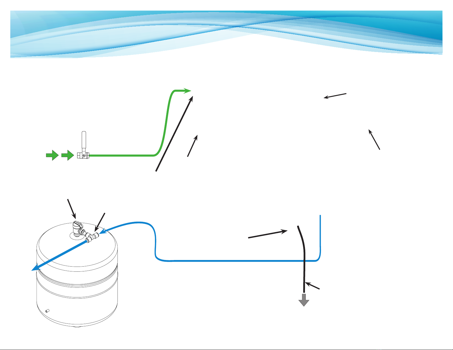
vBWS175 Installation Diagram
Plumbing should be performed in
accordance with local codes.
Feed Water Line -
Green 3/8” - from Feed Water
Valve to Feed Water Inlet
Feed
Water Bypass Valve
Drain Line -
Black 1/4” - from
Permeate Pump to Drain
Reject Water
(To Drain)
User-Supplied
Feed Water
Valve
AMS-Q15 Membrane
Cartridge
To Tank Connection
When installing, locate the storage
tank as near the equipment as
possible to maximize water pressure
and ow. Cut tubing to an efficient
length using a proper tube cutter for
a clean, square cut. When routing
and securing tubing avoid loops or
kinks.
Membrane Reject
Connection
Optimized Water Line to Tank
- Blue 3/8” - from Processor “To
Tank” Connection to Tank Inlet
Storage
Tank Inlet (On Valve)
Optimized Water Storage Tank
- 2.5 gals. Bladder Tank Shown
Storage Tank
Valve
(Normally Open)
CTO-Q10 Pre-Filter
Cartridge
Feed Water Inlet
Water Processor
Optimized Water to
Equipment - Blue 3/8" -
from Tank to Equipment
IMPORTANT - PROTECT PROCESSOR AND TANK
FROM THE ELEMENTS. DO NOT INSTALL IN DIRECT
SUNLIGHT OR WHERE EXPOSED TO FREEZING
TEMPERATURES OR RAIN.
TDS Monitor
Install next to processor
TDS MONITOR
MODEL SM-1
o
ON/OFF
Blending Valve

BWS175 Simple Install Guide 5
Mount the system with the Pre-Installed Drain Line
(1/4” black), Bypass Assembly (3/8” red), and Blend
Valve Assembly (1/4" blue) as shown below.
Step 1
Attach the system with 2 screws (user supplied) through the attachment keyholes shown
below. Use anchors or attach directly to studs. Be sure to allow at least 3” clearance
below cartridges for removal.
vMount Processor
Use Keyholes in Bracket

BWS175 Simple Install Guide 6
Step 2a
Insert the AMS-QT15 Membrane into the center
head and rotate it to the right 1/4 turn to lock.
Step 2b
Remove the plug from the tting at the bottom
of the Membrane and insert the end of the
black tubing coming from the lower left part of
the Permeate Pump.
Attention: Warranty will be void if
this step is not performed properly.
Step 3
Insert and lock the CTO-Q10 Cartridge into the
Pre-Filter Head as shown.
NOTE: The pre-lter head has a built-in shut o
valve. When the lter is removed, water will not
ow. When the lter is installed, water will ow
to the system.
vInstall Membrane
vInstall the Pre-Filter
...To Bottom
of Membrane
BWS175 Simple Install Guide 7
v
Make Drain Connection
vMake Feed Connections
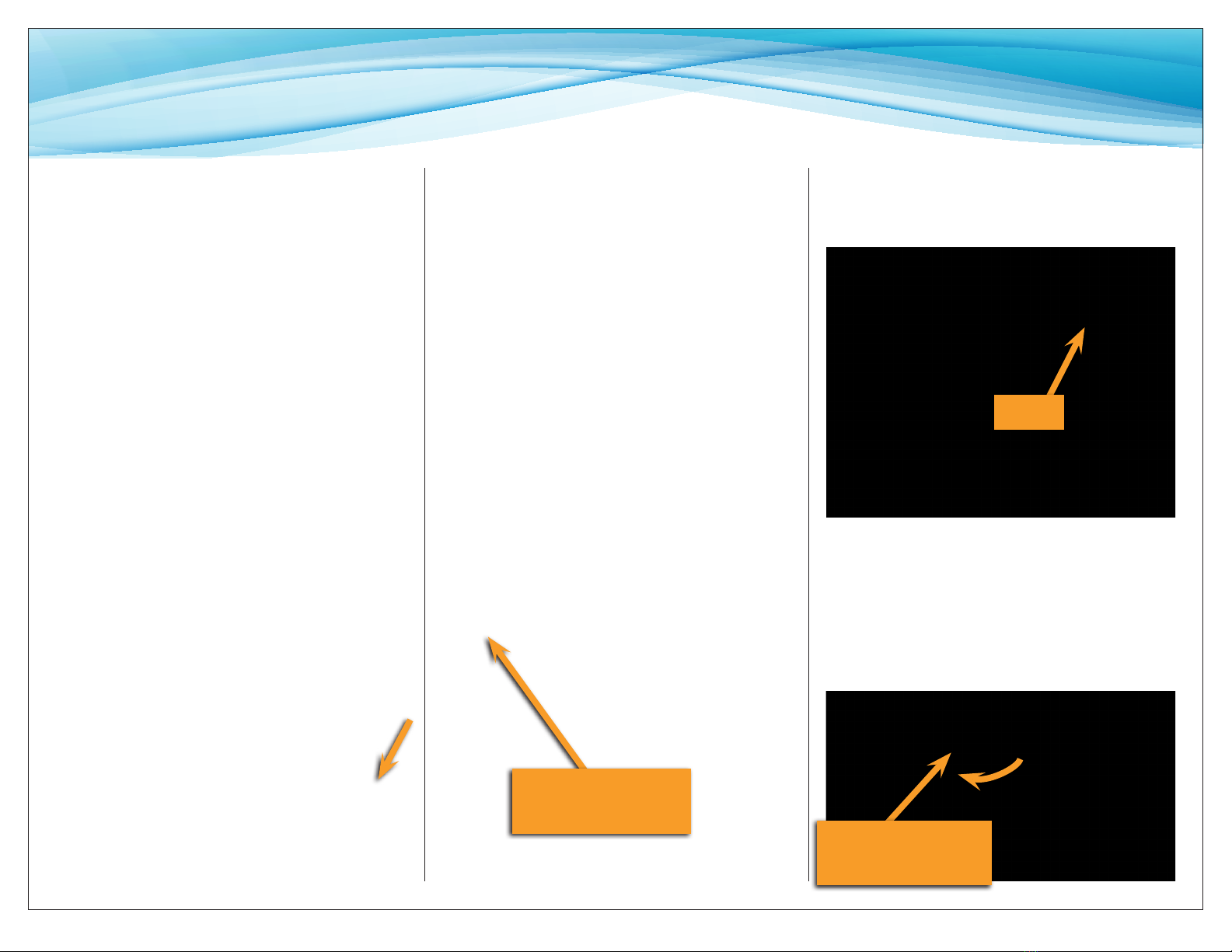
Step 4
Route and connect the loose end of 1/4” black
(DRAIN) tubing coming from Permeate Pump on
processor to a suitable drain; cut to length and
fasten to the wall and at the drain connection.
(Some locations may require an approved air
gap. Optional OptiPure Air Gap available, part
number: 164-89905)
Step 5a
Install the Feedwater Adapter (from the
installation kit) into the user-supplied 1/2”
Feedwater Supply Valve. (Do not over-tighten.)
Step 5b
Connect a piece of 3/8” green tubing to the
Feedwater Supply Valve. Connect the other end
to the Feedwater Inlet on processor.
Step 6
Install the Tank Valve – hand tighten. Cut a piece
of 3/8” tubing 1 1/2” to 2” long and install the
3/8” Tee as shown above. Ensure the Valve is
CLOSED.
Step 6
Feedwater Adapter
(Supplied)
v
Install Tank Valve
and Tee Assembly
Tank Valve in
CLOSED position

BWS175 Simple Install Guide 8
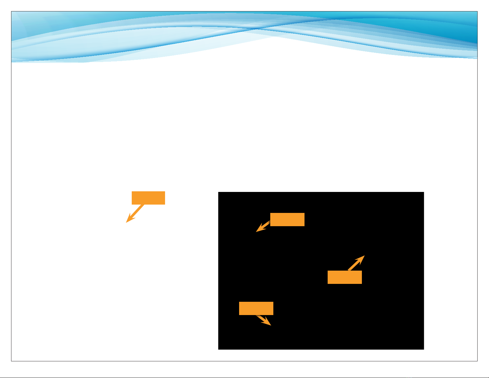
Follow instructions below and proceed to next step.
Step 7a
Connect a piece of 3/8” blue tubing to the
Optimized Water Fitting from the processor.
Connect the other end to the Tank Tee as
shown below.
Step 7b
The remaining connection at the Tank Tee is the
Optimized Water Outlet. Connect a piece of 3/8”
blue tubing to the Tank Tee. This will later be
the water supply connection to downstream
equipment.
Do not connect to equipment at this
time.
vMake Optimized Water Connections
Step 7a
Step 7a
Step 7b

BWS175 Simple Install Guide 9
vMake TDS Monitor Connection
Installing the TDS monitor.
Step 7c
Install TDS Monitor next to the RO processor
using sticky tape with Velcro (supplied with
monitor). Connect TDS Probe to 1/4" tee
fitting located right before Optimized Water
to Storage Tank fitting connection.
Step 7c
TDS Probe
BWS175 Simple Install Guide 10
Step 10
Open the Feed Valve. Allow water to ow to
drain until all air is purged from the system.
Close the Feed Valve after ushing.
Note: During normal operation the water ow
alternates between the optimized water line
and the drain line. You will notice that the
water ow pulses when the system is making
water.
Step 9a
Ensure Bypass Valve is CLOSED.
Step 9b
Ensure Tank Valve is CLOSED.
Step 8
Temporarily route the 3/8” blue tube from the
Optimized Water Outlet on the Storage Tank
Line to a drain or sink.
Step 9b
Step 10
Step 9a
v
Flush the System
Step 8

BWS175 Simple Install Guide 11
vSet Blending Valve & Connect to Equipment
Step 11a
Route and secure the 3/8” blue tube from the
Optimized Water Outlet on the Tank to the
downstream equipment connection.
Step 11b
Make the connection to the equipment.
Connect ONLY the treated/steam water
connection at the equipment. Do notconnect to
the drain/condensate supply.
Optimized Water
to Equipment
Step 11ab Step 12
Tank Valve in
Open position
Step 12
Turn the Tank Valve to the OPEN position. The
installation is complete and the system is ready
to be placed into service.
Step 11
Set blending valve to desired optimized
water TDS:
•Close the Storage Tank valve and
run optimized water line to drain
temporarily.
•Push the "on/off" button on the
water quality monitor. It will display
the optimized water's TDS (total
dissolved solids) in PPM (parts per
million).
•To increase Optimized water TDS
turn the blending valve knob
counter-clockwise, this will increase
the amount of filtered water
blending with the re-mineralized RO
water.
•To decrease Optimized water TDS
turn the blending valve knob
clockwise, this will decrease the
amount of filtered water blending
with re-mineralized RO.
•Once the desired TDS is obtained
allow the system to run for several
minutes periodically checking the
TDS. Make smaller incremental
adjustments as necessary until the
TDS " target" is achieved.

BWS175 Simple Install Guide 12
If a water supply to downstream
equipment is immediately
needed, the storage tank can be
quickly lled.
v
Place in Service
Step 13
OPEN the Feed Suppy Valve and check for
leaks. Allow time for the tank to ll before
using connected equipment (this could take 30
minutes to several hours depending on the
tank capacity).
Step 13
v
Quick Tank Fill
Open Bypass
Simply OPEN the Bypass Valve and un-ltered
water will ow directly into the storage tank.
When the tank is full, or a desired level is
reached, CLOSE the Bypass Valve. The system is
now in normal operating mode and the
optimized water will flow to the tank.
IMPORTANT: Do not leave the system in
bypass. This could result in damage to the
downstream equipment.

BWS175 Simple Install Guide 13
Open Closed
vOperation
The system operates normally when water,
under pressure, is supplied to the system.
Typical filter replacement is every 6 months
(CTOS-Q10 and ILMA-10.14). Typical
membrane replacement is every 24 months
(AMS-QT10) or less, based on water quality.
EMERGENCY BYPASS
In the event the water supply or pressure to
downstream equipment becomes inadequate
OPEN the Built-In Bypass Valve and resume
normal use of equipment. When finished using
equipment return the Valve to the CLOSED
position. DO NOT leave the system in bypass
mode for prolonged periods of time.
IMPORTANT: Leaving the system in bypass
could cause damage to downstream
equipment. If the problem persists contact
your OptiPure dealer for assistance.
Step 1
Close Feed Water Supply Valve.
OR
Be sure Bypass Valve is closed and turn
pre-lter cartridge 1/4 turn to the left .
Step 2
Close the Storage Tank Valve.
Tank Valve in
CLOSED position
vSHUT OFF WATER TO SYSTEM
The water is now shut o and the system is
ready for lter or membrane replacement or
other maintenance.
To return to normal operation reverse these
steps.
Table of contents
Other Aquion Water Filtration System manuals


Popular Water Filtration System manuals by other brands


Clean Water Systems
Clean Water Systems Pro-Ox 5900-BT-AIR Series Installation & maintenance guide

Brita
Brita WD 3030 manual

BWT
BWT Quick & Clean instruction manual

Grunbeck
Grunbeck MRA25 Operation manual

King Industrial
King Industrial KDCF-8300 instruction manual

Grunbeck
Grunbeck desaliQ:BA Series Operation manual