AquiStar PS98i User manual

For PSIG
sensors, refer
to page 6
regarding
desiccant
use!
AquiStar®
PS98i/PS9800
Submersible Pressure Transmier
INSTRUCTION MANUAL

1
Information in this document is subject to change without notice and does not
represent a commitment on the part of the manufacturer. No part of this manual may
be reproduced or transmitted in any form or by any means, electronic or mechanical,
including photocopying and recording, for any purpose without the express written
permission of the manufacturer.
©1997 - 2013 Instrumentation Northwest, Inc.
Registered trademarks and trademarks belong to their respective owners.
Table of Contents
Introduction - PS98i & PS9800 4-20 mATransmitters...................................................2
Initial Inspection and Handling.........................................................................................2
Do’s and Don’ts ................................................................................................................2
General Information..........................................................................................................3
Installation.........................................................................................................................5
Monitoring Wells.......................................................................................................5
Other Installations......................................................................................................6
Maintenance......................................................................................................................6
Desiccant Tubes.........................................................................................................6
Miscellaneous............................................................................................................7
Troubleshooting................................................................................................................7
Erratic Readings.........................................................................................................7
Oscillating Readings Over Time................................................................................7
Zero Readings When Pressurized.............................................................................8
Technical Specifications....................................................................................................8
Component and Wiring Information..........................................................................9
Mechanical Specifications ......................................................................................10
Electrical Specifications ..........................................................................................10
Adaptors...................................................................................................................11
Reordering Information ..................................................................................................11
Accessories .....................................................................................................................11
LIMITED WARRANTY/DISCLAIMER - PS98i/PS9800 ...........................................12

2
Introduction - PS98i & PS9800 4-20 mA Transmitters
These pressure transmitters represent the latest state-of-the-art technology and have
been designed to provide trouble-free submersible operation in liquid environments,
when properly installed and operated. Please take the time to read through this manual
if you are not familiar with this product.
Initial Inspection and Handling
Upon receipt of your transmitter, inspect the shipping package for damage. If any
damage is apparent, note the signs of damage on the appropriate shipping form. After
opening the carton, look for concealed damage such as a cut cable. If concealed dam-
age is found, immediately file a claim with the carrier.
Check the etched label on the transmitter to be sure that the proper range and type were
provided. Also check the label attached to the cable at the connector end for the proper
cable length.
Do’s and Don’ts
Do handle the device with care.
Do store the device in a dry, inside area when not in use.
Do install a desiccant tube if you are doing long-term outdoor monitoring.
Don’t install the device so that the connector end is submerged.
Don’t support the device with the connector or with the connectors of an extension
cable. Use a strain relief device to take the tension off the connectors.
Don’t allow the device to free-fall down a well at high velocities as impact damage
can occur.
Don’t bang or drop the device on hard objects.
Don’t disassemble the device. (The warranty is void if transmitter is disassembled.)

3
General Information
The following paragraphs outline the basics of how pressure is measured using sub-
mersible pressure transmitters:
Liquids and gasses do not retain a fixed shape. Both have the ability to flow and are
often referred to as fluids. One fundamental law for a fluid is that the fluid exerts an
equal pressure in all directions at a given level. Further, this pressure increases with
an increasing depth of “submergence”. If the density of a fluid remains constant
(noncompressible...a generally good assumption for water at “normal” pressures and
temperatures), this pressure increases linearly with the depth of “submergence”.
We are all “submerged” in the atmosphere. As we increase our elevation, the pressure
exerted on our bodies decreases as there is less of this fluid above us. It should be
noted that atmospheric pressure at a given level does vary with changes in the weather.
One standard atmosphere (pressure at sea level on a “normal” day) is defined to be 14.7
PSI (pounds per square inch).
There are several methods to reference a pressure measurement. Absolute pressure is
measured with respect to an ideal vacuum (no pressure). Gauge pressure is the most
common way we express pressure in every day life and is the pressure exerted over and
above atmospheric pressure. With this in mind, gauge pressure (Pg) can be expressed
as the difference between the absolute pressure (Pa) and atmospheric pressure (Patm):
Pg = Pa - Patm
Pressure Diagram

4
To measure gauge pressure, atmospheric pressure is subjected to one side of the system
and the pressure to be measured is subjected to the other. The result is that the dif-
ferential (gauge pressure) is measured. A tire pressure gauge is a common example of
this type of device.
Recall that as the level of submergence increases (in an incompressible fluid), the pres-
sure increases linearly. Also, recall that changes in weather cause the absolute atmo-
spheric pressure to change. In water, the absolute pressure Pa at some level of depth
(d) is given as follows:
Pa = Patm + kd
where k is simply a constant (i.e.: 2.307 ft of water = 1 PSI)
Pressure Diagram, Detail “A”
INW’s standard gauge submersible pressure devices utilize a vent tube in the cable
to allow the device to reference atmospheric pressure. The resulting gauge pressure
measurement reflects only the depth of submergence. That is, the net pressure on the
diaphragm is due entirely to the depth of submergence.

5
Installation
The PS98i & PS9800 measure pressure. The most common application is measuring
liquid levels in wells and tanks. In order to do this, the transmitter must be installed
below the water level at a fixed depth. The installation depth depends on the range of
the transmitter. One (1) PSI is equal to approximately 2.31 feet of water. If you have
a 5 PSI transmitter, the range is 11.55 feet of water and the transmitter should not be
installed at a depth below 11.55 feet. If the transmitter is installed below its maximum
range, damage may result to the transmitter and the output reading will not be correct.
Monitoring Wells
Lower the transmitter to the desired depth. Fasten the cable to the well head using tie
wraps or a weather proof strain-relief system. When securing the cable, make sure not
to pinch the cable too tightly or the vent tube inside the cable jacket may be sealed off.
Take a measurement to insure the transmitter is not installed below its maximum range.
It is recommended that several readings be taken to insure proper operation after instal-
lation.
Important Note: If the transmitter is to be left in the well for a long-term
monitoring application and the connector end is not in a dry, thermally-stable
environment, a desiccant tube must be installed in line with the cable to pre-
vent condensation in the cable vent tube. Water in the vent tube will cause
inaccurate readings and, in time, will work its way into the transmitter and
damage it.
Installation

6
Other Installations
The transmitter can be installed in any position; however, when it leaves the factory it is
tested in the vertical position. Strapping the transmitter body with tie wraps or tape will
not hurt it. If the transmitter is being installed in a fluid environment other than water,
be sure to check the compatibility of the fluid with the wetted parts of the transmitter.
INW can provide a variety of seal materials if you are planning to install the transmitter
in an environment other than water.
Maintenance
Desiccant Tubes
On vented sensors, inspect the desiccant tube at least once every two months. The des-
iccant tube prevents moisture in the air from being sucked into the vent tube, which can
cause erratic readings and sensor damage.
The desiccant tube is filled with blue silica gel beads. A locking barb and a hydrophobic
water filter are attached to the end of the desiccant tube. This filter prolongs the life of
the desiccant as much as three times over a desiccant tube without the filter.
Install the sensor so that the desiccant tube will not flood or lie in water.
The desiccant is a bright blue color when active and dry. As moisture is absorbed the
color will begin to fade, becoming a light pink, which indicates full saturation and time
to replace. Replacement desiccant and hydrophobic filters can be purchased from INW;
please contact an INW sales engineer for more information.
The desiccant tube prevents water intrusion through the vent tube. Be sure to
replace the desiccant when it turns pink, as that indicates it is saturated.
Vent tube
Cable
Desiccant tube Hydrophobic filter

7
Miscellaneous
Sensor: There are no user-serviceable parts, other than the batteries. If problems
develop with sensor stability or accuracey, contact INW. If the transducers have been
exposed to hazardous materials, do not return them without notification and authoriza-
tion.
Cable: Cable can be damaged by abrasion, sharp objects, twisting, crimping, crushing,
or pulling. Take care during installation and use to avoid cable damage. If a section
of cable is damaged, it is recommended that you send your sensor back to replace the
cable harness assembly.
End Connections: The contact areas (pins & sockets) of the connectors will wear out
with extensive use. If your application requires repeated connections other types of
connectors can be provided. The connectors used by INW are not submersible, but are
designed to be splash-resistant.
Troubleshooting
Erratic Readings
Erratic readings can be caused by a damaged transmitter, damaged cable, poor connec-
tions or improper operation of readout equipment. In most cases, erratic readings are
due to moisture getting into the system. Assuming that the readout equipment is work-
ing correctly, the first thing to check is the connection. Look for moisture between
contacts or a loose or broken wire. If the connection appears OK, pull the transmitter
up a known distance while monitoring its output. If the transmitter responds approxi-
mately as it should, but the reading is still erratic, most likely the cable is damaged. If
the transmitter does not respond approximately as it should, it is most likely that the
sensor is damaged. In either case, consult the factory.
Oscillating Readings Over Time
If, after time, your transmitter is functioning normally but your data is showing a
cyclic effect in the absence of water level changes, you are probably seeing baromet-
ric changes. The amount is usually .5 to 1.5 feet of water. This can be caused by a
plugged vent tube in the cable or actual water level changes in the aquifer itself in re-
sponse to barometric pressure changes. This effect can occur in tight formations where
the transmitter will immediately pick up barometric changes but the aquifer will not. If
you think you are having this type of problem you will have to record the barometric
pressure as well as the water level pressure and compensate the data. If it appears that
the vent tube is plugged, consult the factory.

8
If a desiccant tube is not installed in line with the cable, water may have condensed in
your vent tube causing it to plug. After you are finished installing the desiccant tube
you can test the vent tube by applying a small amount of pressure to the end of the
desiccant tube and seeing if this affects the transmitter reading.
Zero Readings When Pressurized
Continuous zero readings are caused by an open circuit which usually indicates broken
cable, a bad connection, or possibly a damaged transmitter. Check the connector to see
if a wire has become loose, or if the cable has been cut. If neither of these appears to
cause the problem, the transmitter needs factory repair.
Technical Specifications
The PS98i submersible pressure transmitter represents the latest in state-of-the-art level
measurement technology. This industry standard two-wire, 4-20 mA device offers
improved noise immunity, thermal performance and transient protection. In addition
to reverse polarity protection, under-current and over-current limitation are featured on
both transmitter channels.
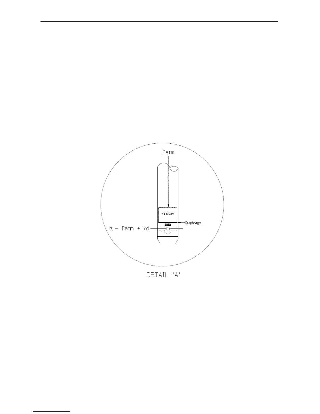
As mentioned above, the PS98i & PS9800 transmitters are current loop devices. This
means that changes in pressure imposed on the stainless steel diaphragm result in
proportional changes in current. The excitation source (DC supply or data logger) sup-
plies the power but the transmitter actually controls how much current flows as long as
the excitation specifications (e.g., voltage level) are met.
For a standard gauge pressure device, there is zero pressure on the diaphragm when
above the surface of the liquid. This zero pressure is converted to a current flow of
4 mA. As the transmitter is lowered into the liquid, the amount of current that flows
increases linearly (with increasing depth) to 20 mA when the maximum rated pressure
(thus depth) is reached. That is, there is a straight line relationship between pressure
(thus depth of submergence) and the amount of current that flows. Adata logger there-
fore can apply power, measure the amount of current that is flowing and convert that to
the depth of submergence using a multiplier and offset (m and b, respectively, for a y =
mx + b straight line) which are preset in the logger by the user.
Compute these m and b values as follows:
m = (Total range of measurement in your units) / 16 / 1000
For example: if you want to measure 0 – 15 psi:
15 / 16 / 1000 = .0009375
b = m * 4000 * (–1)
Using our 0 – 15 psi example above, this would be
.0009375 * 4000 * (–1) = –3.75

9
Component and Wiring Information
Wiring Information
Cable Type: 9-conductor, vented
PS9800
4-20 mA pressure only
Shield = ground
White = (V+) pressure
Blue = pressure signal return
4-20 mA pressure and temperature
Shield = ground
White = (V+) pressure
Blue = pressure signal return
Yellow = (V+) temperature
Purple = temperature signal return
PS98i
4-20 mA pressure only
Shield = ground
White = (V+) pressure
Blue = pressure signal return
4-20 mA pressure and 30K thermistor
Shield = ground
White = (V+) pressure
Blue = pressure signal return
Yellow = resistance
Purple = resistance
Transmitter Components
0.28”
(0.7 cm) Cable
Water
Inlets
Diameter 0.75” (1.9 cm)
8.30”
(21.081 cm)

10
Mechanical Specifications
TRANSMITTER
Body Material 316 stainless steel
Wire Seal Materials Fluoropolymer and PTFE
Desiccant High- and standard-
capacity packs available
Terminating Connector Available
Weight .75 lbs. (0.3 kg)
CABLE
OD 0.28” (0.7 cm) maximum
Break Strength 138 lbs. (62.7 kg)
Maximum Length 2000 feet (610 meters)
Weight 4 lbs. per 100 feet
(1.8 kg/30 m)
Electrical Specifications
PRESSURE
Transmitter Voltage 9-24 VDC, 100 ms warmup
PS9800 Static Accuracy ±0.1% FSO (maximum)
(B.F.S.L. 25° C) (±0.25% for 1.1-5 PSIg, 5.8-12 FtH2O, 1.75-3.5 mH2O)
PS98i Static Accuracy ±0.25% FSO (maximum)
(B.F.S.L. 25° C) ±0.1% FSO (optional)
Thermal Error ±2.0% FSO (maximum)
(0-50° C, reference 25° C) ±0.8% FSO (typical)
Maximum ±0.5% FSO
Zero Offset at 25° C
Over Range 2x [except 300 PSIA
Protection (210 mH2O)]
Compensated 0 - 50° C
Temperature Range
Operating -5° C to 70° C
Temperature Range
TEMPERATURE (PS9800 optional)
Transmitter Voltage 9-24 VDC, 100 ms warm-up
Output Range 0-50° C >> 4-20 mA
Accuracy ±0.75° C (maximum)
(100 ms warm-up) ±0.3° C (typical)
Temperature Range 0 - 50° C
Operating
Temperature Range -5° C to 70° C

11
Adaptors
The following adaptors are available. Contact your INW representative for details and
ordering information.
1/4” male NPT pipe fitting
1” male pipe adaptor
1” conduit adaptor
Reordering Information
For sales & service offices, please contact:
Instrumentation Northwest, Inc.
www.inwusa.com
800-776-9355
Accessories
• 7A40110 Desiccant Tube Replacement
• 7A50517 Strain Relief Kit
• 7A40413 Lightening Protection Module Kit
Also see our entire pressure/level sensor lineup on our web page at
www.inwusa.com/pressurelevel.html.
• PT2X: Pressure/Temperature with datalogging (Modbus and SDI-12)
• PT2X-BV: Barometric/Vacuum pressure with datalogging (Modbus and SDI-12)
• PT2X Wet/Wet: Differential pressure with datalogging (Modbus and SDI-12)
• PT12: Pressure/Temperature without datalogging (Modbus and SDI-12)
• PT12-BV: Barometric/Vacuum pressure w/o datalogging (Modbus and SDI-12)
• PS9805: Pressure ( mV output)
• BV9800: Barometric/Vacuum pressure (4-20 mA)

12
LIMITED WARRANTY/DISCLAIMER - PS98i/PS9800
A. Seller warrants that products manufactured by Seller when properly installed, used
and maintained with a properly installed desiccant tube, shall be free from defects in
material and workmanship. Seller’s obligation under this warranty shall be limited to
replacing or repairing the part or parts or, at Seller’s option, the products which prove
defective in material or workmanship within ONE (1) year from the date of delivery,
provided that Buyer gives Seller prompt notice of any defect or failure and satisfac-
tory proof thereof. Any defective part or parts must be returned to Seller’s factory or
to an authorized service center for inspection. Buyer will prepay all freight charges
to return any products to Seller’s factory, or any other repair facility designated by
Seller. Seller will deliver replacements for defective products to Buyer (ground freight
prepaid) to the destination provided in the original order. Products returned to Seller
for which Seller provides replacement under this warranty shall become the property of
Seller.
This limited warranty does not apply to lack of performance caused by abrasive materials, cor-
rosion due to aggressive fluids, mishandling or misapplication. Seller’s obligations under this
warranty shall not apply to any product which (a) is normally consumed in operation, or (b) has a
normal life inherently shorter than the warranty period stated herein.
In the event that equipment is altered or repaired by the Buyer without prior written approval by
the Seller, all warranties are void. Equipment and accessories not manufactured by the Seller
are warranted only to the extent of and by the original manufacturer’s warranty.
THE FOREGOING WARRANTIES ARE IN LIEU OF ALL OTHER WARRANTIES,
WHETHER ORAL, WRITTEN, EXPRESSED, IMPLIED OR STATUTORY. IMPLIED
WARRANTIES OF FITNESS AND MERCHANTABILITY SHALL NOT APPLY. SELLER’S
WARRANTY OBLIGATIONS AND BUYER’S REMEDIES THEREUNDER (EXCEPTAS
TO TITLE) ARE SOLELYAND EXCLUSIVELYAS STATED HEREIN. IN NO CASE
WILL SELLER BE LIABLE FOR CONSEQUENTIAL DAMAGES, LABOR PERFORMED
IN CONNECTION WITH REMOVALAND REPLACEMENT OF THE SENSOR SYSTEM,
LOSS OF PRODUCTION OR ANY OTHER LOSS INCURRED BECAUSE OF INTERRUP-
TION OF SERVICE. A NEW WARRANTY PERIOD SHALL NOT BE ESTABLISHED
FOR REPAIRED OR REPLACED MATERIAL, PRODUCTS OR SUPPLIES. SUCH ITEMS
SHALL REMAIN UNDER WARRANTY ONLY FOR THE REMAINDER OF THE WAR-
RANTY PERIOD ON THE ORIGINAL MATERIALS, PRODUCTS OR SUPPLIES.
B. With respect to products purchased by consumers in the United States for personal use, the
implied warranties including but not limited to the warranties of merchantability and fitness for a
particular purpose, are limited to twelve (12) months from the date of delivery.
Some states do not allow limitations on the duration of an implied warranty, so the above limita-
tion may not apply to you. Similarly, some states do not allow the exclusion or limitation of
consequential damages, so the above limitation or exclusion may not apply to you. This limited
warranty gives you specific legal rights; however, you may also have other rights which may
vary from state to state.

8902 122nd Avenue NE
Kirkland, WA 98033 USA
425-822-4434
FAX 425-822-8384 / [email protected]
INW
©1997 - 2013 by Instrumentation Northwest, Inc. All rights reserved. Instrumentation Northwest and INW
are trademarks registered with the U.S. Patent & Trademark Office. Doc# 9B0005r8 10/24/13 / PN 3A341-NI
This manual suits for next models
1
Table of contents
Popular Transmitter manuals by other brands

PR electronics
PR electronics 2261 manual

EUTECH INSTRUMENTS
EUTECH INSTRUMENTS ALPHA COND 200 - REV 3 instruction manual

Mobrey
Mobrey 9700 Series Instruction leaflet

Western Electric
Western Electric 6-B Instructions for use

BBC Bircher
BBC Bircher Swissdoor RFGate 3.1 370046A Original operating instructions

MTS Sensors
MTS Sensors Level Plus M Series Operation and installation manual