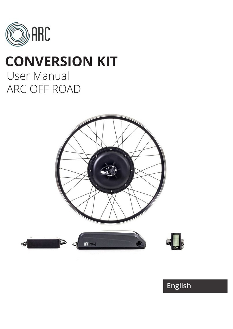
ARC FEATHER User manual

USER MANUAL ARC
LAST UPDATED: 3/08/2018 1
ARC FEATHER USER MANUAL
The complete guide on how to assemble, operate and maintain your
new electric bike.
ENGLISH

USER MANUAL ARC
LAST UPDATED: 3/08/2018 2
We at Arc would like to thank you for your purchase. Your support is crucial to
helping us achieve excellence in the electric bicycle arena. Should you have any
quesons about your product that aren’t covered in this manual, please contact
us directly or speak to your local Arc dealer.
We hope that you love your new Arc Feather kit, and wish you a safe onward
journey.
Though we at Arc perform an extensive safety check prior to the dispatch of
each of our bikes and kits, we recommend that you go over each part of your
new kit with tools of your own, from me to me. Regular maintenance will
ensure the safe and smooth operaon of your kit well into the future.
MECHANICAL SAFETY CHECK
Prior to embarking on your maiden ride, we recommend taking a moment to
familiarise yourself with the performance controls outlined in this manual.
Ensure that there is adequate space in front of the bike before beginning your
rst ride and remember to wear a helmet at all mes. Compleng these few
tasks will ensure your rst ride, and every ride thereaer, is a safe one.
FIRST RIDE CHECK
THANK YOU!

USER MANUAL ARC
LAST UPDATED: 3/08/2018 3
TABLE OF CONTENTS
EBike Components and Terminology........................................................4
Assembly..................................................................................................6
Unboxing...........................................................................................6
Inventory...........................................................................................7
Bicycle Preparaon ...........................................................................8
Motor..............................................................................................10
Baery ............................................................................................15
Handlebar .......................................................................................17
Pedal Assistance..............................................................................18
Wiring .............................................................................................21
Operaon...............................................................................................22
Baery Charging .............................................................................22
Display operaon…………………………………………..…See separate manual
Baery Informaon ...............................................................................23
Maintenance..........................................................................................26
Troubleshoong Tips..............................................................................27
Troubleshoong Table............................................................................28
Contact Us .............................................................................................29
Please note that this manual shows the rst version of the Arc Feather kit, so
some of the components in your kit may look slightly dierent. The installaon
instrucons however remain the same.

USER MANUAL ARC
LAST UPDATED: 3/08/2018 4
This secon will help you understand the operaon of your new electric bicycle
and the common terms and components involved. If you are familiar with what
an electric bike is and how they operate, then feel free to skip over this secon.
Otherwise, we recommend that you familiarise yourself with these terms.
An electric bike consists of mulple electronic components that are powered
from the baery. The most common components of an electric bike are:
A) Electric Motor
B) Motor Controller
C) Baery
D) Handlebar Display
E) Throle (Oponal)
F) Pedal Assistance Sensor and Magnet Ring
G) Electric Brake Cut-os (E-brake cut-os) - not part of the Arc Feather kit
EBIKE COMPONENTS AND TERMINOLOGY

USER MANUAL ARC
LAST UPDATED: 3/08/2018 5
A) Electric Motor
The muscle. This component applies rotaonal force to the wheels and propels
the bicycle forward. Motors can either be hub drive (in the wheel) or mid drive.
B) Motor Controller
The brain. This complex piece of electronics takes input from other components
and operates the motor. The motor controller is generally built into the frame
of the electric bicycle, but can be found aached to the motor or outer frame.
C) Baery
The heart. Without this component there will be no speedy take o or smooth
runs over hills. The baery of an electric bike is generally a Lithium Ion type
(though some are sll lead acid). They have baery management systems that
ensure the safe operaon and charging of the baery.
D) Handlebar Display
The ears and eyes. This component takes in input from the rider and
communicates it to the motor controller,. It can also use that informaon to
restrict the motor controller’s operaon. This device usually allows the rider to
change pedal assistance levels and check baery levels.
E) Throle (Oponal)
This device is controlled by the rider and is typically located on the handlebar.
When the rider uses the throle, it will propel the bike forward.
F) Pedal Assistance Sensor and Magnet Ring
Another input to the motor controller. This component detects the rotaon of
the pedals and alerts the motor controller. The motor controller then acvates
power to the motor based on the seng requested on the handlebar display.
G) Electric Brake Cut-os (E-brake cut-os)
Typically aached to the brakes or built in to the brakes, this component
detects the actuaon of the brakes and cuts power to the motor. This is an
added safety feature built into most electric bikes that use pedal assistance.

USER MANUAL ARC
LAST UPDATED: 3/08/2018 6
This secon will help you complete the inial setup of your electric bike kit. This
informaon will likely only be required if you purchased your bicycle kit online
or from a venue separate to our retail stores, though it may be helpful for new
users too.
ASSEMBLY
The moment of unboxing of your new electric bike kit is an excing me and,
while we wouldn't ever want to take that from you, we do urge cauon during
the unboxing process. Enthusiascally cung into the box with a cardboard
knife or pair of scissors may lead to unintended scratches or damage to your
new kit before you've even had a chance to use it and nobody wants that.
We recommend having a partner on hand to help you remove the bicycle from
its packaging as doing it by yourself can be a dicult process. Your bike may be
quite heavy, and making it a two-person job ensures you'll be able to get it out
of the box without the risk of injury to yourself or your bike.
Carefully remove all packaging and wrapping from each secon of the bicycle
frame, always being mindful not to damage any part of the bike or its
components with any tools you may use.
ASSEMBLY—UNBOXING

USER MANUAL ARC
LAST UPDATED: 3/08/2018 7
This is what the inside of the carton is likely to look like. The motor on the right
side, baery in the middle le, charger boom le and the other parts and
accessories in the top le box.
TOOLS REQUIRED:
• Spanner set or shiing spanner
• Set of Allen keys
• Pair of side cuers/scissors
• Tyre levers (may not be required)
• Addional zip es (oponal)
• Strong adhesive (oponal)
ASSEMBLY—INVENTORY

USER MANUAL ARC
LAST UPDATED: 3/08/2018 8
This secon will detail some of the basic steps you should undertake to prepare
your bicycle for conversion.
ASSEMBLY—BICYCLE PREPERATION
The rst thing you should do is nd a suitable space in which to conduct the
installaon. If you don’t have a nice so surface to ip the bike over onto, or
don’t have a bike maintenance stand, then we recommend using some of the
foam packaging in the kit to prevent any unintended damage to your bike.
As in the photographs above, ip the bike over in preparaon for removing the
front wheel motor mounng. In the case of the bike pictured, the front wheel
was quick release making it very easy to remove without tools. You may require
a spanner or shier to remove the front wheel, depending on the construcon
of your bicycle.

USER MANUAL ARC
LAST UPDATED: 3/08/2018 9
Once the wheel has been removed, check if your bicycle has a front disk brake.
If so, you will need to remove the disk brake for mounng onto the front motor.
ASSEMBLY—BICYCLE PREPERATION
Some disk brakes may require specialist tools to remove, though most will only
require a standard 5mm Allen key. Once you have removed the disk brake,
place it aside for the next step.
Unless you purchased a new tyre and tube to go with the motor, you will also
need to remove the current wheel’s tube and tyre for relocaon to the hub
motor from the conversion kit. Deate the tyre and remove the tyre and tube.
This can usually be done by hand, though it may require some tyre levers to
help get the job done. You should avoid using tyre levers if you can as they can
lead to a higher likelihood of tyre puncture. Just start on the side opposite to
the tube’s valve, removing the tyre from the rim and work your way around
unl the tyre is completely removed.

USER MANUAL ARC
LAST UPDATED: 3/08/2018 10
Now that the bicycle has been prepared, the motor can be mounted on the
bicycle.
ASSEMBLY—FRONT MOTOR
Remove the motor from its packaging if you have not done so already. At this
point you can remount the tyre and tube, making sure you get the direcon
right. This is typically marked on the side of tyre tube. The motor has a cable
coming out of the right side which may help you get the correct direcon.
If you have removed a disk brake in the previous secon, you should remount it
on the motor now. To do this, you can remove the Allen key bolts from the
motor as shown above. The motor has a plasc spacer in the posion of the
disk brake as a placeholder. Remove this and mount the disk brake in posion.
Be sure to ghten the bolts evenly all the way round.

USER MANUAL ARC
LAST UPDATED: 3/08/2018 11
Now to mount the motor into the front forks.
ASSEMBLY—FRONT MOTOR
Familiarise yourself with the washers and their posions. Ensure that the
torque washers (which are the washers with a notch) are both on the same way
on the axle.
Line the torque washers up with the axle slots. As you can see in the
photograph on the right, the torque washer will not t in the axle slot with the
current washer conguraon. We will need to remove the internal washer from
the setup so that the torque washer is the only washer present on that side.
This secon is dierent for every bike and will require some common sense to
complete the install.

USER MANUAL ARC
LAST UPDATED: 3/08/2018 12
Another observable issue is that the calliper is ever-so-slightly rubbing against
the disk.
ASSEMBLY—FRONT MOTOR
To solve this, we recommend loosening the brake calliper before readjusng
the washer posions so that the axle will correctly slot into the front dropouts.
As you can see from the pictures above, the motor has been mounted into the
front forks with enough clearance for the disk brake and the motor. The motor
can now spin in the drop outs without rubbing on the disk brake calliper or the
frame in any way.

USER MANUAL ARC
LAST UPDATED: 3/08/2018 13
With the motor sloed in the front forks and able to rotate without running
afoul of the frame or brakes, the nal stage of assembly can begin.
ASSEMBLY—FRONT MOTOR
Insert washers on the axle on both sides to completely ll out the secon so
the axle nut will have a nice at surface to ghten up to. Once the washers are
in place ghten the nuts up with a spanner/shier.
Ensure that your brake calliper is ghtened up again. You have now completed
the front motor installaon. The bicycle can be ipped back to its vercal
posion for the remainder of the installaon process. Ensure that the tyres are
properly inated before ipping over.

USER MANUAL ARC
LAST UPDATED: 3/08/2018 14
There are a lot of important steps and consider while mounng the front
wheel. Let’s take a moment to summarise the front motor assembly:
• Install tyre and tube
• Install disk brake rotor (if required)
• Check that washer posions are similar on both sides
• Aempt to insert the motor into the drop outs.
• If the motor does not t inially, check what it is fouling on (disc brake,
washer posion or frame)
• If the motor is fouling because of the washer posion, adjust washer
posions to create more or less space as required to t the motor.
• If the motor is fouling because of the disk brake posion, adjust the brake
calliper to create more space as required.
• If the motor is fouling on a part of the bicycle frame, you may be doing
something incorrectly or the bicycle may simply be incompable with this
kit. Please contact support right away for assistance.
• Once the motor has been mounted on the forks, secure the motor by
ghtening down the axle nuts. Ensure that washers are placed on the axle
before ghtening the axle nuts.
Take each step slowly and ensure that it ts before moving onto the next step.
The motor will rarely have to be forced into posion and, if mounted correctly,
should be rotang without rubbing on any part of the frame. Each bicycle is
slightly dierent to convert and will require some common sense to complete.
If you get stuck at any point or your are concerned you’ve made a mistake,
please contact support at once.
ASSEMBLY—FRONT MOTOR SUMMARY

USER MANUAL ARC
LAST UPDATED: 3/08/2018 15
This part explains how to connect the baery and install it onto the handlebars.
ASSEMBLY—BATTERY
Remove the baery from its packaging. This a small bag that holds the baery
and the motor controller. As in the image in the upper right, the bag has ve
plugs. On the le side is the motor plug and the charger plug. On the right is
the display (green), throle (yellow) the pedal assistance (yellow). There are 3
straps that are available for mounng the pouch onto the handlebars.
Before mounng the baery onto the handlebars, it is likely that the baery is
physically disconnected inside the pouch for safe transport. Locate the two
plugs and connect them with the arrows poinng towards each other. If yours
look dierent than the photo above, make sure you connect red to red and
black to black. Once these are connected, you can reinsert the baery and
motor controller back into the pouch.

USER MANUAL ARC
LAST UPDATED: 3/08/2018 16
ASSEMBLY—BATTERY
There are 3 straps for mounng the pouch onto the handlebars — two that are
vercal straps designed to run directly around the handlebars as shown in the
top right image, and a single horizontal strap that can then be wrapped around
a part of the handlebar stem.
You have now completed the installaon of the baery onto the handlebars.

USER MANUAL ARC
LAST UPDATED: 3/08/2018 17
As there are only two components that require installing on the handlebars,
this stage of the installaon is quite simple.
To install the thumb throle, remove one side of the handlebar components
(like your grip and brake lever) and slide the thumb throle into the posion
that is most suitable for you. There is a small Allen key on the boom side of
the throle that ghtens the device to the handlebars once you nd a posion
you're happy with. Ensure that the place washer is inserted as well. This
prevents the thumb throle from geng stuck on other components. Connect
the yellow plug to the matching plug from the handlebar bag.
To install the display, loosen the screw in the clamp, clamp the display onto the
handlebars, and ghten the screw back up. Connect the green plug to the
matching plug from the handlebar bag.
ASSEMBLY—HANDLEBAR COMPONENTS

USER MANUAL ARC
LAST UPDATED: 3/08/2018 18
This secon will explain how to install your pedal assistance sensor to the
bicycle.
ASSEMBLY—PEDAL ASSISTANCE
Pictured above is the pedal assistance sensor (PAS) and the magnet wheel. The
magnet wheel will aach around the boom bracket crank sha.
If your boom bracket crank sha looks similar to the one in the lower le
picture, then it is likely your bike will be directly compable with this type of
pedal assistance sensor. The magnet wheel can be split in half so that you do
not have to remove the crank arm from the bicycle (which would require
specialised tools). One side of the magnet wheel is marked as the working side
and is completely at. This side will face the bike.

USER MANUAL ARC
LAST UPDATED: 3/08/2018 19
ASSEMBLY—PEDAL ASSISTANCE
Clip the two halves of the pedal assistance sensor around the crank sha as
shown, with the working side facing the bicycle. Then aach the metal circlip
around the magnet wheel, securing it in place. This magnet wheel should
rotate with the pedals when the pedal cranks are rotated.
Now to t the PAS. The PAS can mounted anywhere on the frame so that the
sensor lines up with the magnets on the magnet wheel. In this case, the best t
for the PAS was on the diagonal down tube pictured in the lower le photo.
This posioning may vary from bike-to-bike.

USER MANUAL ARC
LAST UPDATED: 3/08/2018 20
To mount the PAS, apply a single zip e around the top secon of the PAS unit.
This will allow you to parally test operaon before mounng it more
permanently. The sensor should be no further than 5mm away from the
magnet wheel and not have a large angle.
ASSEMBLY—PEDAL ASSISTANCE
Now that the PAS is ed, when the system is turned on the and the pedals are
turned, the motor will acvate. You will noce that the light on the PAS will
ash when the system is operang. If this is not ashing you may need to adjust
the sensor’s locaon/angle so that the sensor is very close to the magnet
wheel.
Other manuals for FEATHER
1
Table of contents
Other ARC Bicycle Accessories manuals