4
Contents
Thank you 2
SAFETY 2
Item check list 3
Installation process 5
Wheel Install 6
Wheel Install continued 7
Battery Cradle Installation 9
Battery Cradle Installation continued 10
Throttles and grips 11
Display 11
E-brake sensors 12
Controller 13
Controller continued 14
Removable Pedal Assist Sensor (RPAS) 15
RPAS Continued... 16
Battery Operation 17
Charging 18
Maintenance and Care 19
Trouble Shooting 20
Trouble Shooting Continued... 21
Trouble Shooting Continued... 22
Trouble Shooting Continued... 23
Specications 24
Before you start your conversion, you will have
to decide if you’re installing the battery on the
down tube (recommended) or on the provided
rear rack. You will also have to decide if you
are going to install a throttle (you can run the
system using just the pedal assist sensor) and
which of the two throttle options is going to
work best with your bike.
Most commonly the thumb throttle is preferred,
as it leaves more room on your handlebars for
other components. Using the thumb throttle
means you can even use your current grips
if you prefer, leaving your handlebars almost
untouched.
One of the many benets of the ARC kits is the
exibility in the installation.
Once you have decided on the ideal conversion
for your bike, it’s time to prepare the bike.
Start by checking over each component and
familiarize yourself with the terminology. A
common mistake is when people refer to the
LCD display as the ‘controller’. The LCD functions
as a readout for the conversion kit. The
controller is actually the rectangular box which
houses the major control components of the
electric system.
Once you have looked over the parts to
familiarize yourself, remove the grips from your
current bikes (if installing a throttle) and turn the
bike upside down so it rests on the seat and the
ends of the handlebars (if you don’t have a bike
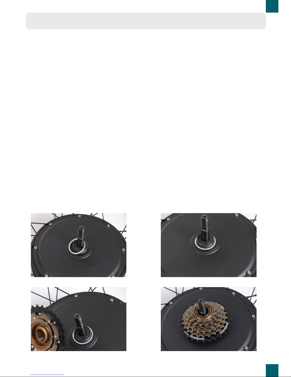
stand). Take the rear wheel out and deate and
remove the tire, tube and rim tape. Install these
onto the new electric wheel.
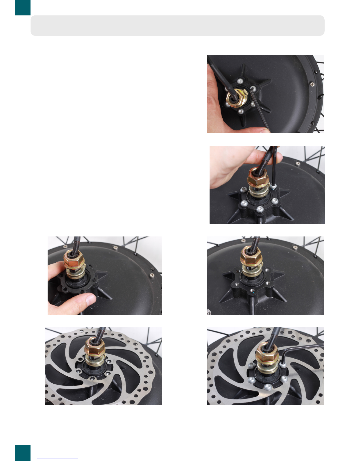
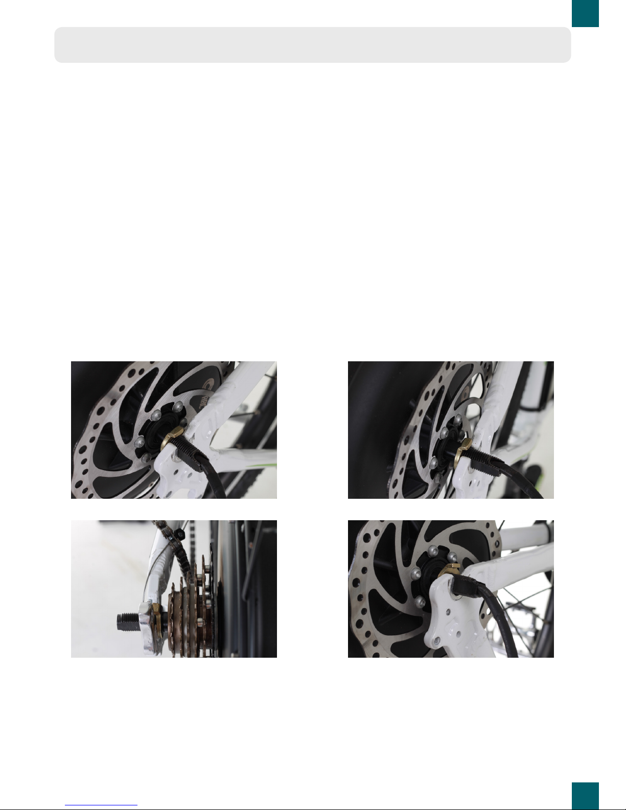
If you’re installing disk brakes, it’s ideal to
remove the caliper which will make it easier to
install the rear wheel.