Arca Flow Weka VLI EconomyLine 6 User manual
Installation and
Operating Manual
Visual Level Indicator (VLI)
Date: 17.03.2020
Version: E 10.1
WEKA_IOM_VLI_EN / 17.03.2020 1 / 31
Notes
Order:
Date:
WEKA_IOM_VLI_EN / 17.03.2020 2 / 31
Content
1. Type overview ............................................................................................................................................................3
2. Symbols and marks used .........................................................................................................................................4
3. Safety information and warnings.............................................................................................................................4
4. Intended use...............................................................................................................................................................5
5. The visual level indicator at a glance ......................................................................................................................6
5.1 The four different types of bypass ......................................................................................................................7
5.2 Top-of-tank design ..............................................................................................................................................7
5.3 Options Indication rail .........................................................................................................................................8
6. Function description .................................................................................................................................................8
7. Scope of delivery for visual level indicator ............................................................................................................9
8. Preparation for assembly .........................................................................................................................................9
8.1 Unpacking ...........................................................................................................................................................9
8.2 Disposing of the packaging.................................................................................................................................9
8.3 Remove float protection ....................................................................................................................................10
9. Installation................................................................................................................................................................13
9.1 Mounting ...........................................................................................................................................................14
9.2 Inspecting..........................................................................................................................................................14
10. Commissioning ...................................................................................................................................................14
11. Maintenance ........................................................................................................................................................15
12. Cleaning visual level indicator ..........................................................................................................................16
12.1 Cleaning the outside .........................................................................................................................................16
12.2 Cleaning the float chamber and the float ..........................................................................................................16
12.3 Cleaning the float chamber and float for a top-of-tank assembly .....................................................................17
13. Operating, transport and storage conditions ..................................................................................................18
13.1 Operating conditions .........................................................................................................................................18
13.2 Transport and storage conditions .....................................................................................................................18
14. Technical data .....................................................................................................................................................18
15. Disassembly / disposal ......................................................................................................................................18
15.1 Disassembly......................................................................................................................................................18
15.2 Disposing of the visual level indicator...............................................................................................................19
16. Troubleshooting..................................................................................................................................................19
17. Label.....................................................................................................................................................................20
17.1 Type plate .........................................................................................................................................................20
17.2 Explosion-proof plate ........................................................................................................................................20
18. Customer service................................................................................................................................................20
19. EU Declaration of Conformity for non-explosion-proof devices ...................................................................21
20. EU Declaration of Conformity for explosion-proof devices ...........................................................................22
21. ATEX Certificate (Type Examination Certificate).............................................................................................23
22. IECEx Certificate of Conformity (CoC) .............................................................................................................26
WEKA_IOM_VLI_EN / 17.03.2020 3 / 31
1. Type overview
23614E EconomyLine 6
34000E EconomyLine 6
23614 StandardLine 6
34300 StandardLine 28
32755 StandardLine 50
34000 SmartLine 50
34110 SmartLine 50
36800 HighPressure Power 80
26411 HighPressure Power 100
25683 HighPressure Power 160
32806 HighPressure Power 200
26421 HighPressure Power 250
26431 HighPressure Power 315
38400 HighPressure Power 400
38500 HighPressure Power 500
39020 PetroLine 20
39021 PetroLine 20-low density
39050 PetroLine 50
39051 PetroLine 50-low density
39068 PetroLine 68
39100 PetroLine 100
39150 PetroLine 150
39250 PetroLine 250
39420 PetroLine 420
39630 PetroLine 630
40350 LowDensityLine 50
Plastic VLI PVDF
,
PP
,
PVC
23013 Top of Tank Line 6
25270/6 Top of Tank Line 6
25270/28 Top of Tank Line 28
25270/50 Top of Tank Line 50
Plastic ToT PVDF, PP, PVC

WEKA_IOM_VLI_EN / 17.03.2020 4 / 31
2. Symbols and marks used
Warning
Indicates possible damage to the visual level indicator or injury to the operator or
user if the instructions are not followed.
Caution
Indicates possible damage to the visual level indicator if the instructions are not
followed.
Safety information
For equipment intended for use in potentially explosive atmospheres in accordance
with the European directive 2014/34/EU (ATEX) or IECEx.
This information is applicable in addition to all other information.
3. Safety information and warnings
The manufacturer accepts no liability for damage caused as a result of failure to comply with the safety
information and warnings.
Risk of burning! Working on hot visual level indicators may result in physical injuries and burns.
The surfaces of the standpipes and the process connections may become hot. Allow the tank to
cool to the ambient temperature before working on the visual level indicator. Wear suitable
protective equipment (gloves, face guard, possibly breathing apparatus). Keep a sufficient
distance away while the machine is in operation.
Visual level indicators run at excessive pressure carry pressure-related risks. Depressurise the
tank before working on the visual level indicator and observe the information in the European
Pressure Equipment Directive 2014/68/EU.
When opening the visual level indicator, bear in mind that the fluids and gases it contains could
be hazardous to health. It is imperative that you comply with the safety data sheets for the
process liquids and gases used.
The visual level indicator may stop working due to the float gauge being blocked, and this may go
unnoticed. If you are unsure about the fluid level shown, the visual level indicator should be
tested using a different method (see “Troubleshooting”)
If you suspect that there is a malfunction or determine that there is one, this must be rectified.
Only use the visual level indicator if you have read and understood this manual in full.
This manual must also be accessible for later users.
Keep magnetic and magnetisable parts (magnets, structural steel, iron wire or iron clips, etc.)
away from the visual level indicator. The same applies for strong electromagnetic fields
(transformers, welding equipment, etc.). Both can interfere with the magnetic force of the
magnets inside the visual level indicator and lead to the gauge and any attached accessories
(switch, transducer) malfunctioning and dropping out.
Replace damaged or faulty components with original replacement parts.
Solvents may dull or crack any plastic parts used. Clean the indication rail with soapy water or a
plastic cleaner.
The visual level indicator must not be installed under mechanical tension.
The visual level indicator must not be used to mechanically reinforce the tank or the system.
WEKA_IOM_VLI_EN / 17.03.2020 5 / 31
Falling parts (screws, floats, etc.) may create impact sparks and lead to an explosion in
potentially explosive atmospheres. Make sure that there isn’t a potentially explosive atmosphere
and that no parts are falling when working on the visual level indicator.
When working on the visual level indicator, only use equipment and tools permitted in
accordance with the European Directive for potentially explosive atmospheres.
Polycarbonate indication rails may become statically charged – e.g. during cleaning. Sparks
created when discharging in a potentially explosive atmosphere may cause an explosion. Only
clean these parts with antistatic cleaning agents and tools.
4. Intended use
The visual level indicator may only be used for fluids.
The visual level indicator may only be used for the purposes recorded on the type plate. The
information noted down on the type plate and data sheet must conform with ideal plant operating
parameters.
Uses not intended by the manufacturer, modifications and alterations to the visual level indicator
are at your own risk and may be dangerous (guarantee exclusion).
The visual level indicator may only be installed, commissioned and maintained by a trained
professional.
The manufacturer accepts no liability for damage caused by incorrect use or operation.
The visual level indicator may only be used for the purposes recorded on the type plate and the Ex
label.
The visual level indicator may only be installed, commissioned and maintained by a trained
professional with expertise in explosion prevention.
The visual level indicator may only be repaired and modified by the manufacturer (or, if
appropriate, in consultation with the notified body).
WEKA_IOM_VLI_EN / 17.03.2020 6 / 31
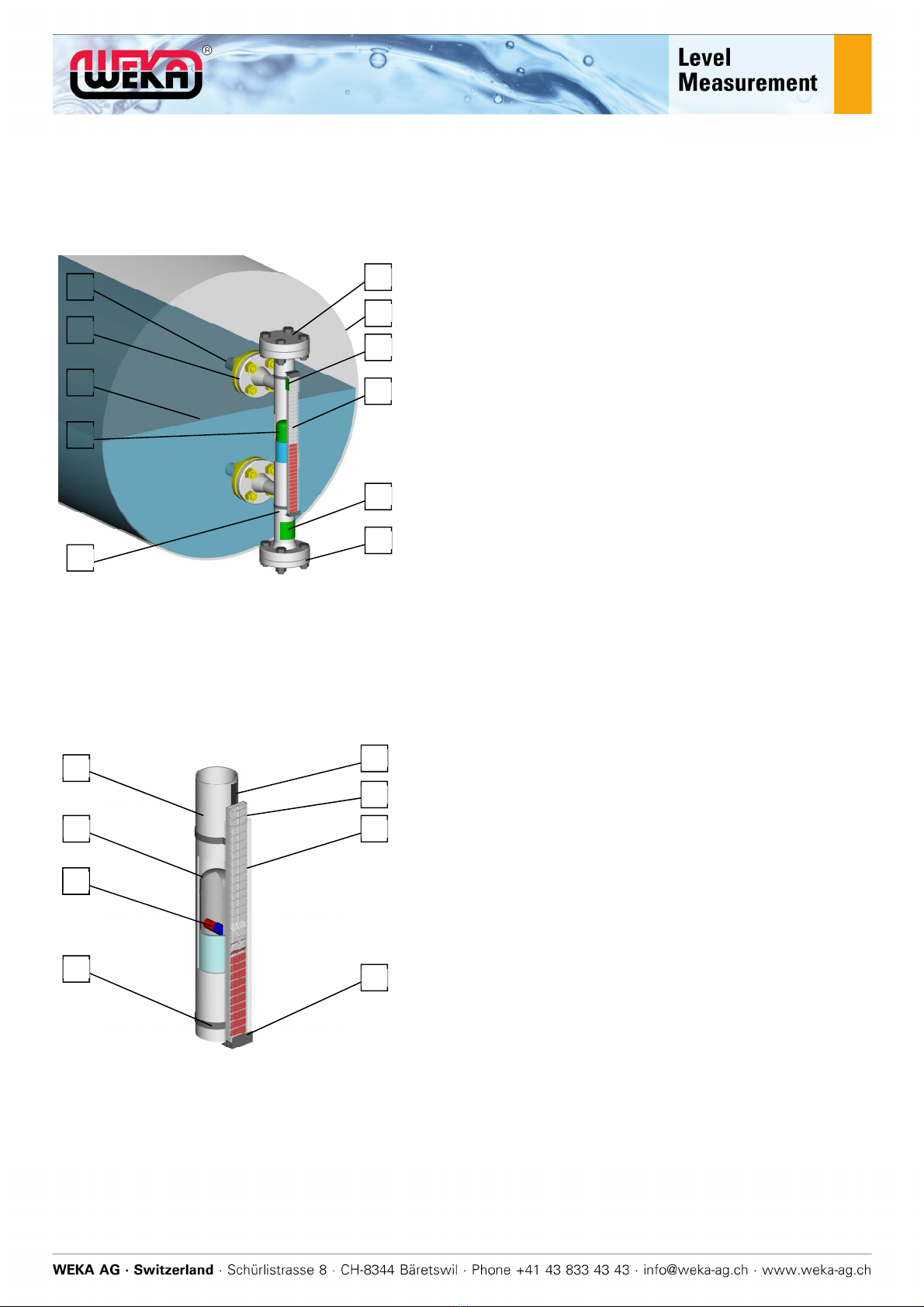
5. The visual level indicator at a glance
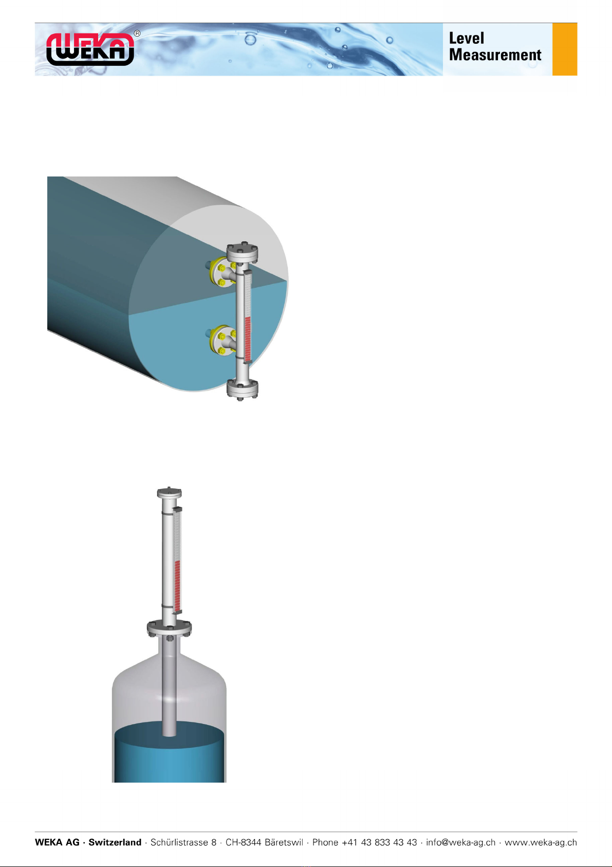
Visual level indicators are used to continuously record the fluid level of the contents of a tank. They are
connected as a bypass on the side of the tank, or as a top-of-tank gauge on the tank.
Figure 4A
Visual level indicators may be built in a way that differs
from the way depicted in this manual, and individual
parts may not be present.
1 Tank (container), supplied by customer
2 Process connections*, supplied by
customer
3 Surface of the liquid
Visual level indicator
4 Process connections*, top and bottom
5 Float chamber
(also called standpipe)
6 Float
7 Indication rail
(see below for details)
8 Type plate
with customer-specific parameters
9 “Top” sticker
10 Service connections*, top and bottom
* Process and service connections may be:
Flanges
Couplers
Weld sockets
Internal and external threads
Figure 4B
A1 Float chamber
A2 Flat with integrated bar magnet
A3 Horizontal bar magnet
A4 Crossed, two-part hose clip*
(also called bride)
* also possible in single-piece design with a
bracket for reinforced mounting
B1 Outer profile**
B2 Inner profile*** with two-tone gauge flaps
inserted
B3 Rotating magnetic band
B4 End caps with seal, screwed
** Aluminium outer profile used with plastic or
glass strips or polycarbonate profile, sealed
*** Aluminium or polycarbonate inner profile,
consistent with outer profile
2
1
3
4
5
6
7
8
9
10
10
A1
B2
A2
A3
A4 B4
B1
B3
WEKA_IOM_VLI_EN / 17.03.2020 7 / 31
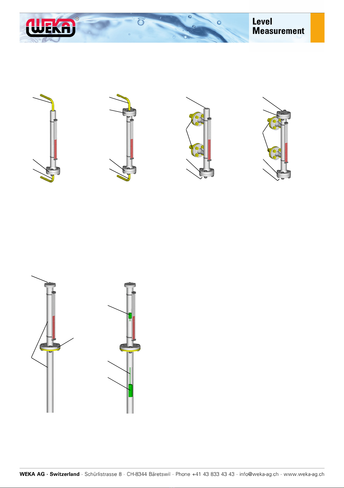
5.1 The four different types of bypass
Type A
Type B Type K Type O
20 Top process connection
21 Top service flange/plug
22 Bottom service flange/plug
23 Bottom process connection
(Drain and vent omitted)
30 Lateral process connections, top and bottom
31 Top service flange/plug
32 Possible ventilation hole with plug
33 Bottom service flange/plug
34 Possible drain hole with plug
5.2 Top-of-tank design
Figure 4.2
40 Float chamber
41 Process connection
42 Service flange, possibly with
ventilation hole and plug
43 Float
44 Rod
45 Magnet holder, possibly rotatable,
with integrated, horizontal bar magnet
20
22
23
20
22
21
23
32
33
34
30
32
33
31
34
30
42
41
40
45
44
43

WEKA_IOM_VLI_EN / 17.03.2020 8 / 31
5.3 Options Indication rail
See data sheets for more options.
Measuring scale Reinforced
indication rail
mounting
Indication rail with
protective hose
Coloured gauge
flaps
6. Function description
The fluid level in the float chamber corresponds to
the fluid level in the tank (communicating vessels).
The bar magnet has been integrated into the float
in a way that means the centre of the bar magnet
is level with the surface of the liquid.
Each float has been designed for a specific liquid
density.
The magnetic band in the indication rail aligns the
bar magnet with the indication rail – like a
compass needle.
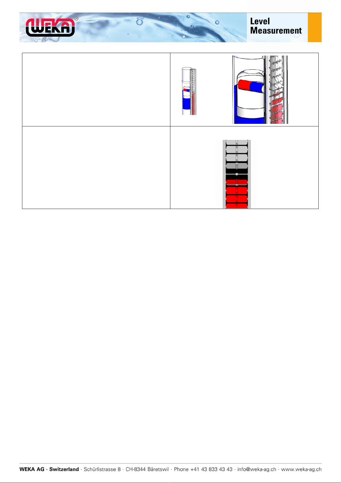
WEKA_IOM_VLI_EN / 17.03.2020 9 / 31
The magnetic field of the bar magnet penetrates
the non-magnetic standpipe and rotates the gauge
flaps by 180° when it goes past.
Information on options: Magnetic switches and
transducers can also be controlled using the bar
magnet in the float.
Magnets built into the gauge flaps keep the gauge
flaps in position (magnetic coupling).
7. Scope of delivery for visual level indicator
Visual level indicator, as ordered
Visual level indicator manual
Works test certificate EN 10204 – 2.2 (function and pressure testing)
Optional: acceptance test certificate EN 10204 – 3.1 (material certificate)
Optional: other certificates like NACE
8. Preparation for assembly
8.1 Unpacking
1. Lay the visual level indicator and the packaging flat on the floor.
2. Remove the packing tape.
3. Remove the staples in the overlapping cardboard at both ends of the packaging with a big
screwdriver or an appropriate tool.
4. Open the packaging and remove the visual level indicator together with the packing trays at both
ends.
5. Carefully remove the packing trays. Make sure that the visual level indicator is on a clean, smooth
surface so that the process connections or supplied parts are not damaged.
6. Make sure that no other parts are in the packaging.
7. Visually inspect the visual level indicator and all the supplied parts for possible damage caused
during transport. Don’t use any damaged or dubious parts.
8.2 Disposing of the packaging
Protect the environment and take the packaging material to be disposed of / recycled properly.

WEKA_IOM_VLI_EN / 17.03.2020 10 / 31
8.3 Remove float protection
If the float is not suitable for the intended use (density, max. operating pressure, max. operating
temperature, connection dimensions, material, etc.), the visual level indicator may display an
incorrect level, and it may be damaged and pose a risk. Make sure that the float is suitable for
the intended application.
Incorrect or incorrectly inserted seals result in leaks. It is imperative that you ensure the correct
seals (material, design) are used for your specific application, and that the seals are positioned
correctly.
Damaged floats adversely affect the functioning of the visual level indicator. Handle the float
carefully and don’t drop it!
Foreign substances in the float chamber adversely affect the functioning of the visual level
indicator. Remove them completely!
An incorrectly installed float will lead to the incorrect fill level being displayed! Slide the float into
the float chamber as shown.
Falling parts (screws, floats, etc.) may create impact sparks and may lead to an explosion in
potentially explosive atmospheres. Make sure that there isn’t a potentially explosive atmosphere
and that no parts are falling when working on the visual level indicator. Only use approved tools.
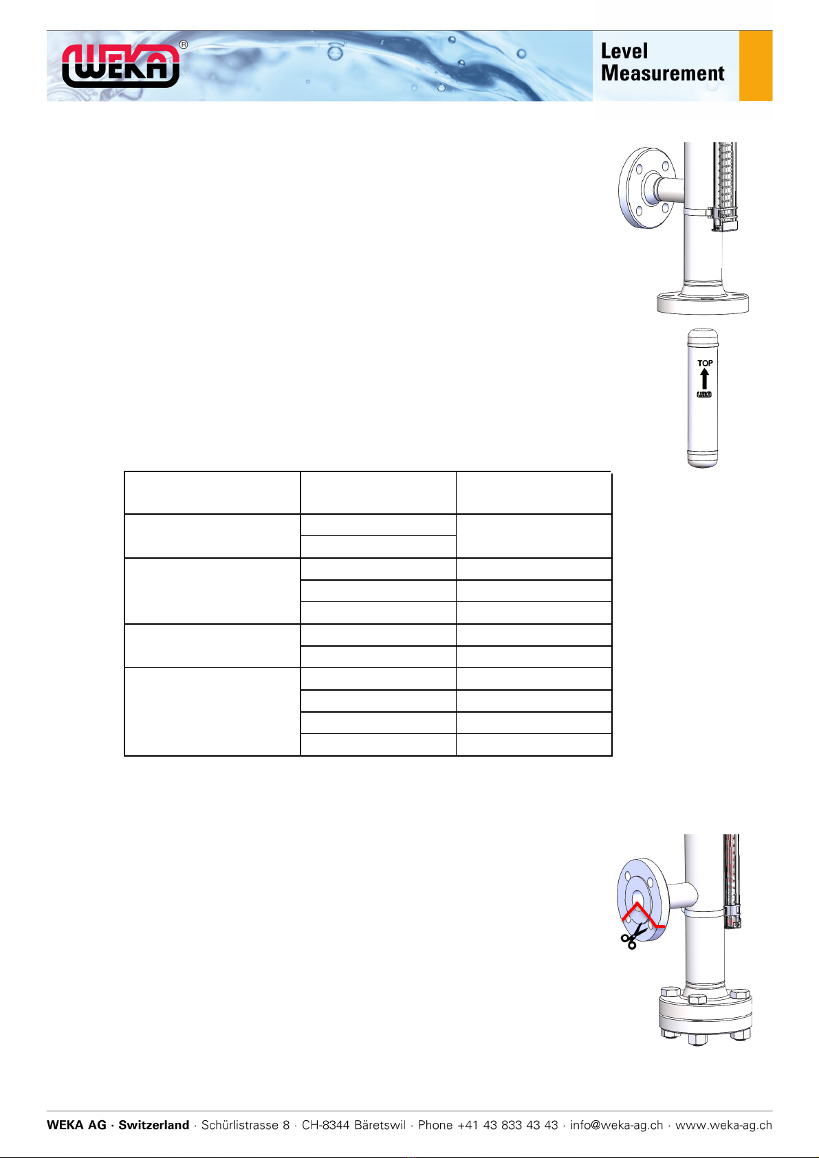
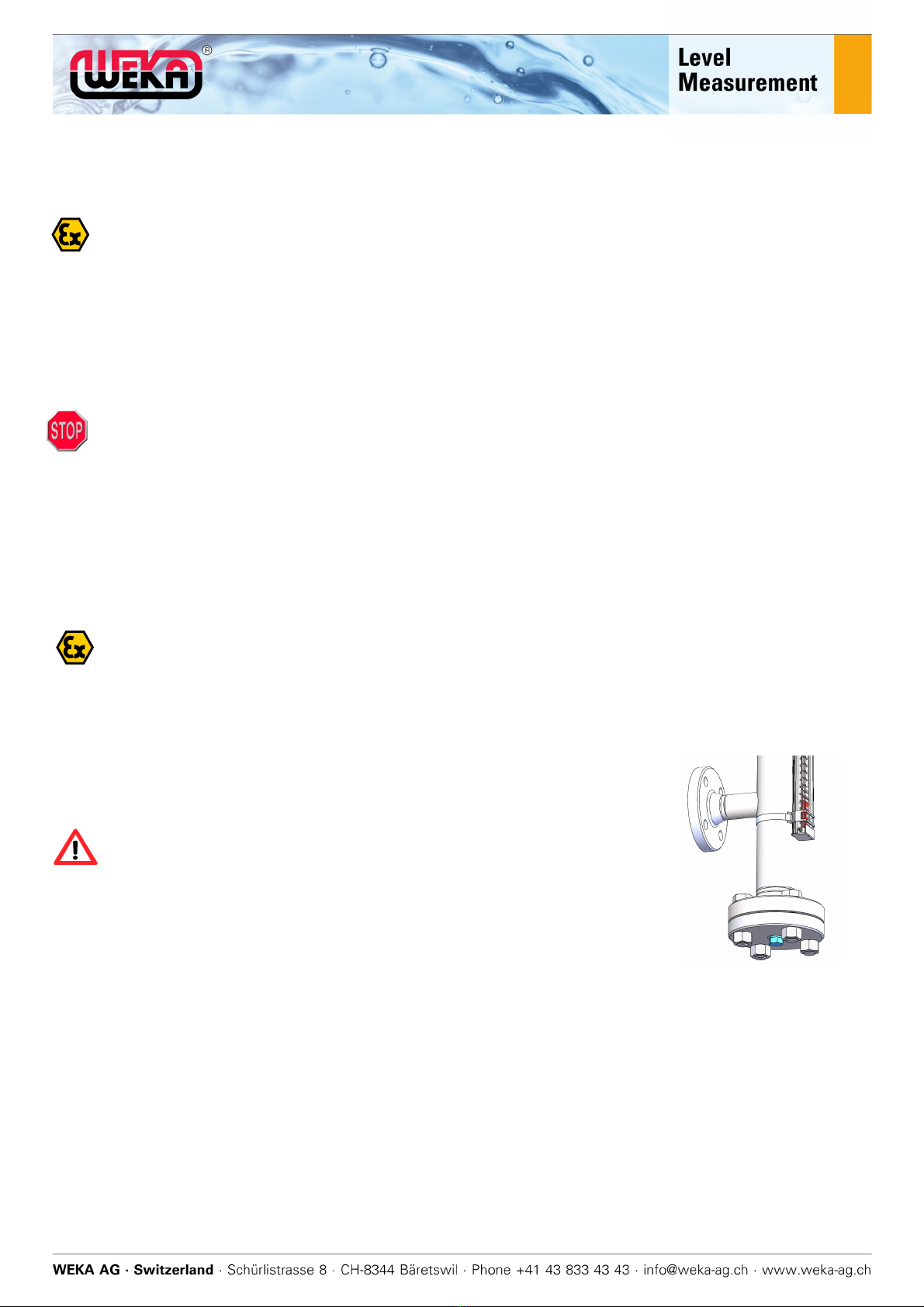
To avoid damage in transit, the float for some designs is secured to the outside of the float chamber
separately in a cardboard tube. For all other devices, it is secured with a safety device inside the float
chamber to the lower process connection using a cord. This needs to be removed / detached before
assembly:
If the float is secured outside the float chamber, follow point A.
If the float is in the float chamber, follow point B.
If it is a top-of-tank gauge, follow point C.
WEKA_IOM_VLI_EN / 17.03.2020 11 / 31
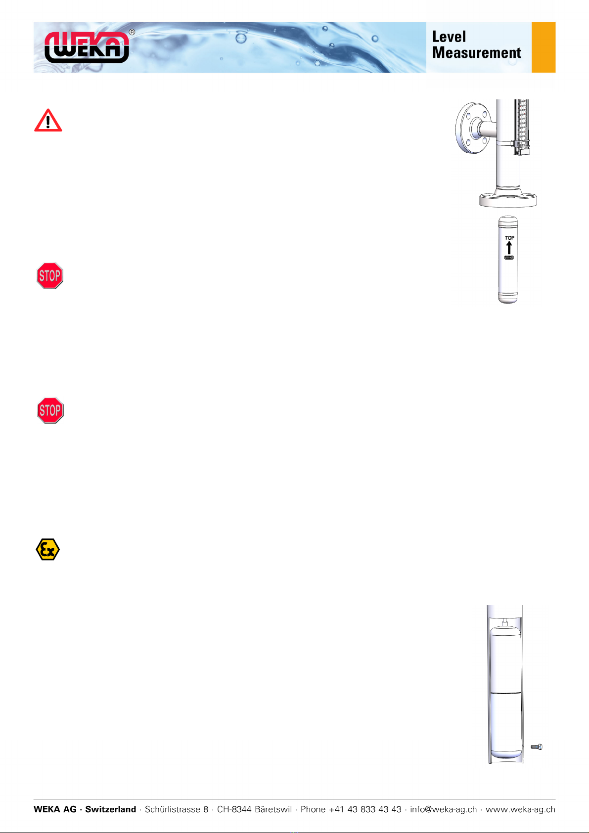
A) Float attached
1. Detach the cardboard tube from the float chamber.
2. Open the cardboard tube and take out the float.
3. Remove the cardboard rings.
4. Remove the bottom service flanges/plugs.
5. Double check that the float is suitable for the chosen application using
the highlighted data.
6. Insert the float into the float chamber so that the arrow with the label
“TOP” is pointing upwards.
7. Bear in mind that the float can now move freely in the float chamber
and may be damaged. You should therefore now move the level gauge
with all due care.
8. Make sure that there are no foreign substances in the float chamber.
9. Make sure that seal has been inserted correctly.
10. Install the bottom service flange/plug. If you’re dealing with a flange,
tighten the screws diagonally. Bear any tightening torque information in
mind.
VLI line VLI type Torque [Nm]
SmartLine 34000 20
34110
StandarLline
23614 20
34300 60
32755 40
EconomyLine 34000E 20
23614E 20
HighPressureLine
36800 45
26411 25
25683 50
32806 50
Further torque values on datasheet, drawing or on request.
11. Remove the protective covers from the process connections.
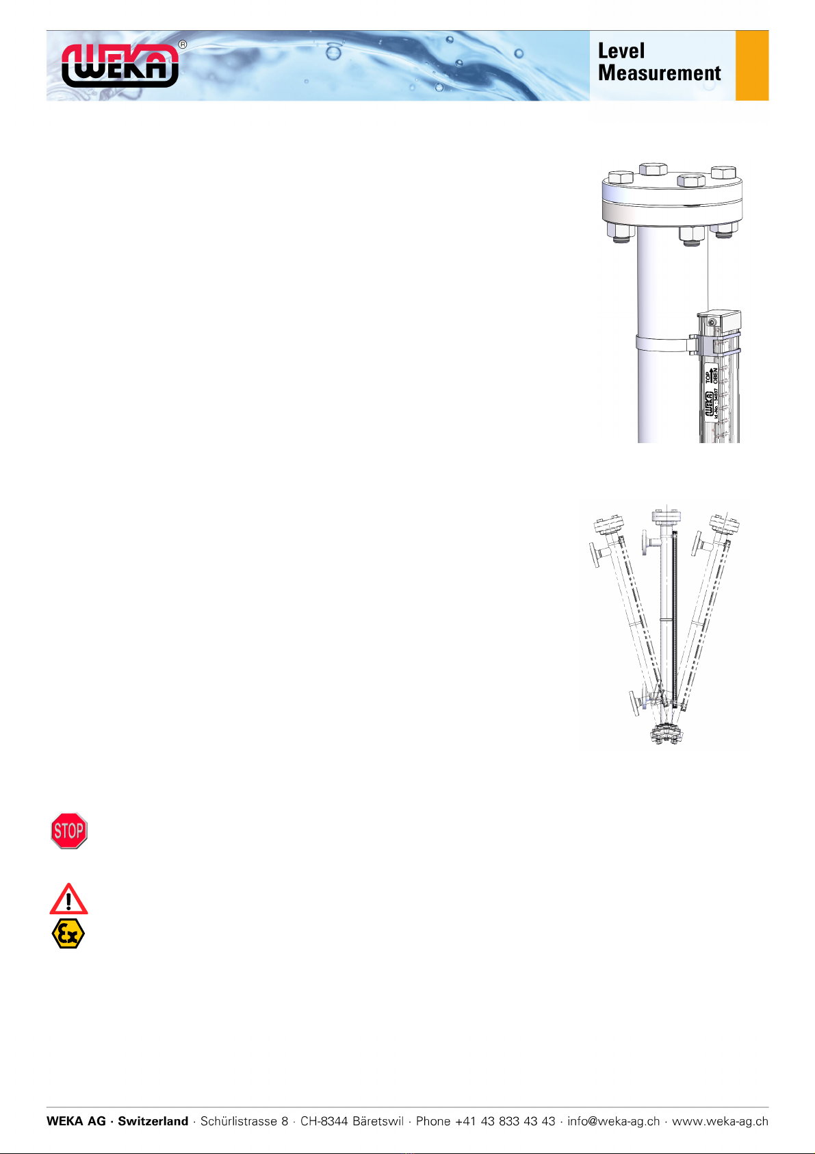
B) Float secured in the float chamber
1. Sever the float safety device from the lower process connection.
2. Pull the float safety device completely out of the process connection
from one end. Make sure that there are no foreign substances in the
float chamber.
3. Bear in mind that the float can now move freely in the float chamber
and may be damaged. You should therefore now move the level
gauge with all due care.
4. Remove the protective covers from the process connections.

WEKA_IOM_VLI_EN / 17.03.2020 12 / 31
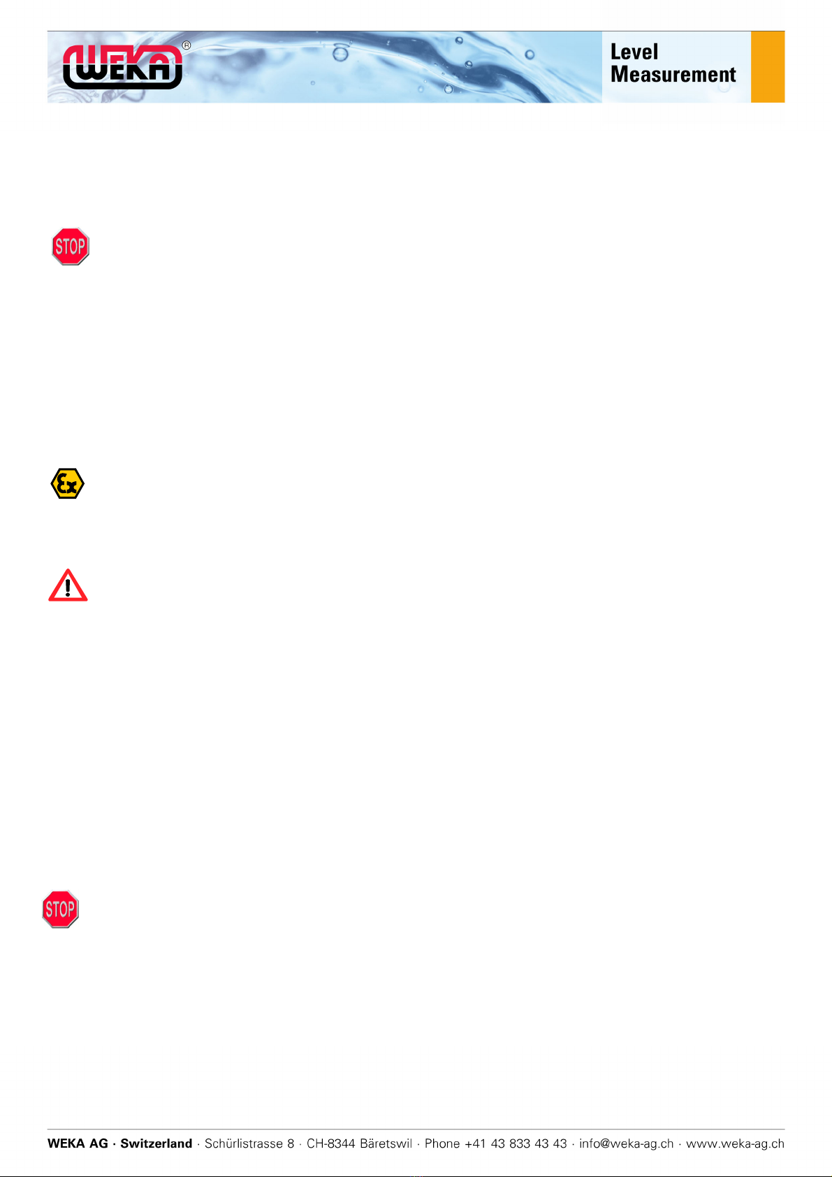
C) Float for top-of-tank designs
1. The float system for the top-of-tank design consists of a floatation body (called
a float here), the magnet holder and the rod that connects the two parts.
2. Type 23013:
The float moves along a guiding pipe and is fixed for transportation by a cable
tie against movement.
Type 25270:
The float is in the float chamber and is stopped from moving around thanks to
a screw at the bottom end of the chamber.
3. Type 23013:
Remove cable tie and dispose properly.
Type 25270:
Turn the screw until the float can move without too much resistance and move
the float further into the float chamber.
4. Bear in mind that the float can now move freely and may be damaged. You
should therefore now move the level gauge with all due care.
5. Type 25270:
Put the screw all the way back in and tighten it so that it can’t go missing. Now the float cannot
fall out.
WEKA_IOM_VLI_EN / 17.03.2020 13 / 31
9. Installation
Preparations for installing (point 8) the visual level indicator must be completed before installation.
If the data marked on the type plate (density, max. operating pressure, max. operating
temperature, connection dimensions, material, etc.), does not match the application, the visual
level indicator may display an incorrect level, and it may be damaged and pose a risk to people
and the environment. Make sure that the data marked on the type plate matches the application.
Unsuitable screws, nuts and seals may result in leaks and cause damage and may endanger
people and the environment. Only use components suited to the application.
For visual level indicators with weld sockets as process connections, only suitable (approved)
welding processes may be used. The same applies to the selection of filler materials.
Working on hot or pressurised visual level indicators may result in physical injuries, burns,
chemical burns or poisoning. Depressurise the tank and allow it to cool to the ambient
temperature before working on the visual level indicator. Wear suitable protective equipment
(gloves, face guard, possibly breathing apparatus).
The visual level indicator may only be used for the purposes recorded on the type plate and the
Ex label.
Falling parts (screws, floats, etc.) may create impact sparks and lead to an explosion in
potentially explosive atmospheres. Make sure that there isn’t a potentially explosive atmosphere
and that no parts are falling when working on the visual level indicator.
In the absence of equipotential bonding, static charges may build up, which may result in
sparking and lead to explosions. To equalise the potential, permanently connect the metallic
housing of the visual level indicator (float chamber) to the equipotential bonding conductor of the
system (tank).
Possible equipotential bonding connections:
-Weld the weld sockets (process connection) to the tank
-Connect the flanges (process connection) to the tank via at least two bolts.
-If none of these are possible, set up an equipotential bonding conductor of at least 4mm²
via a clamp connection.
-The connection points must be free of paint.
Also, the accessories, like magnet switches, transmitters, etc. must be connected to the potential
equalisation system.
WEKA_IOM_VLI_EN / 17.03.2020 14 / 31
9.1 Mounting
1. Lay out the tools, lifting aids, screws, nuts and seals that you need to
install the visual level indicator.
2. Position the visual level indicator on the tank. When doing so, make
sure that the TOP sticker on the indication rail is pointing upwards.
3. If needed, add seals to the connection threads or between the flange
connections.
-Flange connections
Tighten the flange connection screws diagonally. Check that the
screw connections are a tight fit.
-Weld sockets
Remember that heat will be built up when welding weld sockets.
Components at risk should be covered, cooled, or temporarily
removed.
-Screw-in threads
The visual level indicator and indication rail must not be used to
provide counter torque when installing the screw-in threads. Use a
suitable tool for counteraction without putting stress on or damaging
mounted parts.
9.2 Inspecting
For all types of installation, make sure that the process connections for the
visual level indicator are aligned with the tank’s process connections.
The visual level indicator must be installed in a vertical position. You can
check this with a spirit level on the float chamber. Deviations of up to 5° from
the vertical position are acceptable. Larger deviations may result in increased
friction on the float in the float chamber and may lead to blockages. It is
imperative that this is agreed with the supplier.
Twisting or bending of the float chamber, caused by incorrect socket
distances for example, may block the float and lead to the visual level
indicator breaking down!
10. Commissioning
Installation (point 8 to point 9) must be fully completed before commissioning.
If the data marked on the type plate (density, max. operating pressure, max. operating
temperature, connection dimensions, material, etc.), does not match the application, the visual
level indicator may display an incorrect level, and it may be damaged and pose a risk to people
and the environment. Make sure that the data marked on the type plate matches the application.
Check the visual level indicator for visible external damage before use. Do not put a damaged
visual level indicator into operation.
The visual level indicator may only be used for the purposes recorded on the type plate and the
Ex label.
WEKA_IOM_VLI_EN / 17.03.2020 15 / 31
The visual level indicator is filled with liquid from the tank. When filling the tank for the first time, bear in mind
that there will not yet be any liquid in the float outlet, and that the float will only float when this dead space
has been filled via the lower socket.
Once the float starts floating, some time will still be needed for it to align with the magnetic band of the
indication rail. From then on, the fill level should be shown when the gauge flaps are turned down.
If any of the gauge flaps are shifted into an incorrect position during transit, it is possible to move them back
to their intended locations using a weak hand-held magnet. This method can also be used to test the
mobility of the gauge flaps by hand. However, they should always then be put back in their original
positions.
It is advisable to completely drain the tank under supervision once, and to visually check the fill level so that
you can guarantee the level gauge is functioning properly.
Just to be on the safe side, check the entire device after it has been filled, including checking the seals for
leaks.
For steam applications, it is imperative that you ensure no pressure surges occur, as this may catapult the
float up into the float chamber and destroy it.
11. Maintenance
Only use the visual level indicator if it is working properly.
Do not use an unsealed visual level indicator.
Working on hot or pressurised visual level indicators may result in physical injuries, burns,
chemical burns or poisoning. Depressurise the tank and allow it to cool to the ambient
temperature before working on the visual level indicator. Wear suitable protective equipment
(gloves, face guard, possibly breathing apparatus).
If you suspect that there is a malfunction or determine that there is one, this must be rectified.
Damaged or faulty components must be replaced by original replacement parts.
The visual level indicator may only be repaired and modified by the manufacturer (or, if
appropriate, in consultation with the notified body).
The visual level indicator is generally maintenance-free.
The level gauge should only be cleaned on the outside – and on the inside if necessary – in the
event of a suspected malfunction, or in any of the circumstances listed below.
Time Scope
While in use
-In the event of a suspected
malfunction
-Periodically, depending on
usage and degree of
contamination
Check visual level indicator for leaks.
If required, clean inside and outside.
Check float for excessive wear marks.
Before each use Check for damage.
For highly-viscous and/or heavily
contaminated process liquids
Periodically clean the inside, depending on degree of
contamination.
After a long period of inactivity Check visual level indicator for leaks.
If required, clean inside and outside.
After cleaning
(see chapter 12)
Check visual level indicator for leaks.
WEKA_IOM_VLI_EN / 17.03.2020 16 / 31
12. Cleaning visual level indicator
12.1 Cleaning the outside
Polycarbonate indication rails may become statically charged – e.g. during cleaning. Sparks
created when discharging in a potentially explosive atmosphere may cause an explosion. Only
clean these parts with antistatic cleaning agents and tools.
Caution
Solvents and scouring agents may cause the indication rail window to become dull or cracked. Clean the
window with soapy water or a plastic cleaner.
12.2 Cleaning the float chamber and the float
Risk of burning! Working on hot visual level indicators may result in physical injuries and burns.
The surfaces of the standpipes and the process connections may become hot. Allow the tank to
cool to the ambient temperature before working on the visual level indicator. Wear suitable
protective equipment (gloves, face guard, possibly breathing apparatus). Keep a sufficient
distance away while the machine is in operation.
Visual level indicators run at excessive pressure carry pressure-related risks. Depressurise the
tank before working on the visual level indicator and observe the information of the local valid
pressure regulations, i.e. Pressure Equipment Directive 2014/68/EU.
When opening the visual level indicator, bear in mind that the fluids and gases it contains could
be hazardous to health. It is imperative that you comply with the safety data sheets for the
process liquids and gases used.
Falling parts (screws, floats, etc.) may create impact sparks and lead to an explosion in
potentially explosive atmospheres. Make sure that there isn’t a potentially explosive atmosphere
and that no parts are falling when working on the visual level indicator.
When using highly contaminated fluids or pipe systems, the float and the float chamber need to be cleaned
frequently.
In fluids with magnetic parts, they cluster on the float’s magnet. Remove them
frequently.
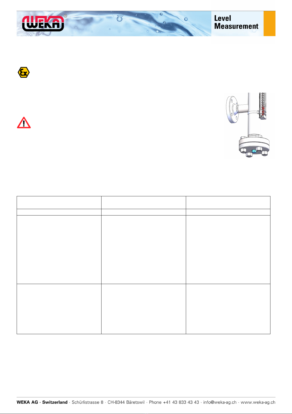
1. Empty the tank.
The float may fall out and get damaged when you remove the
connection flange.
Remove the float chamber via the lower service connection, see
Figure (Service plug/flange).
Remove the lower service plug/flange and the float.
2. Clean the float chamber and the float with a suitable cleaning agent.
WEKA_IOM_VLI_EN / 17.03.2020 17 / 31
3. Check the float.
Floats with heavy signs of wear need to be replaced occasionally. When
ordering replacements, make a note of the serial/order number and the
item number to make clear assignment possible.
If the density noted on the float doesn’t match with the density of the fluid,
the visual level indicator will show an incorrect fill level. Consult your
authorised WEKA dealer before using a float from a different visual level
indicator.
An incorrectly installed float will lead to the incorrect fill level being
displayed!
4. Slide the float into the float chamber as shown.
Unsuitable screws, nuts and seals may result in leaks and cause damage
and may endanger people and the environment. Only use components
suited to the application.
5. Reseal the service connection, as described in point 9.1.
Recommission the visual level indicator, as described in point 10.
12.3 Cleaning the float chamber and float for a top-of-tank assembly
Risk of burning! Working on hot visual level indicators may result in physical injuries and burns.
The surfaces of the standpipes and the process connections may become hot. Allow the tank to
cool to the ambient temperature before working on the visual level indicator. Wear suitable
protective equipment (gloves, face guard, possibly breathing apparatus). Keep a sufficient
distance away while the machine is in operation.
Visual level indicators run at excessive pressure carry pressure-related risks. Depressurise the
tank before working on the visual level indicator and observe the information of the local valid
pressure regulations, i.e. Pressure Equipment Directive 2014/68/EU.
When opening the visual level indicator, bear in mind that the fluids and gases it contains could
be hazardous to health. It is imperative that you comply with the safety data sheets for the
process liquids and gases used.
Falling parts (screws, floats, etc.) may create impact sparks and lead to an explosion in
potentially explosive atmospheres. Make sure that there isn’t a potentially explosive atmosphere
and that no parts are falling when working on the visual level indicator.
1. Remove the visual level indicator.
2. Loosen the lower float stopper (usually a screw in the guide pipe which stops
the float from falling out) until you can remove the float.
3. Clean the float chamber and the float system with a suitable cleaning agent.
Check the float system (floatation panel, connecting pipe and magnet holder)
for damage and replace them if needed.
Floats with heavy signs of wear need to be replaced occasionally. When
ordering replacements, make a note of the serial/order number and the item
number to make clear assignment possible.
WEKA_IOM_VLI_EN / 17.03.2020 18 / 31
4. Put the float system back in the float chamber and fit the float stopper, see chapter 8.3.
5. Reinstall the visual level indicator on the tank.
Unsuitable screws, nuts and seals may result in leaks and cause damage and may endanger
people and the environment. Only use components suited to the application.
6. Recommission the visual level indicator, as described in point 10.
13. Operating, transport and storage conditions
13.1 Operating conditions
According to the type plate and order confirmation / drawing
Environment (standard):
-Temperature: -20°C to +60°C
-Relative humidity: 10% to 95%
The operating and ambient conditions may be restricted for products for use in potentially
explosive atmospheres. Please comply with the information on the type plate and explosion-proof
plate.
13.2 Transport and storage conditions
-Protect the visual level indicator from severe jolts.
-Do not place heavy items on the visual level indicator or its packaging.
-To avoid damage in transit, secure the flat with a safety device.
-Store the visual level indicator in a dry environment.
-Avoid contact with water and moisture
-Temperature: -40°C to +80°C
-Relative humidity: 10% to 95%
14. Technical data
General information can be gathered from the data sheet for the model in question.
Order-specific data as per type plate and order confirmation / drawing.
15. Disassembly / disposal
15.1 Disassembly
Risk of burning! Working on hot visual level indicators may result in physical injuries and burns.
The surfaces of the standpipes and the process connections may become hot. Allow the tank to
cool to the ambient temperature before working on the visual level indicator. Wear suitable
protective equipment (gloves, face guard, possibly breathing apparatus). Keep a sufficient
distance away while the machine is in operation.
Visual level indicators run at excessive pressure carry pressure-related risks. Depressurise the
tank before working on the visual level indicator and observe the information of the local valid
pressure regulations, i.e. Pressure Equipment Directive 2014/68/EU.
WEKA_IOM_VLI_EN / 17.03.2020 19 / 31
When opening the visual level indicator, bear in mind that the fluids and gases it contains could
be hazardous to health. It is imperative that you comply with the safety data sheets for the
process liquids and gases used.
Falling parts (screws, floats, etc.) may create impact sparks and lead to an explosion in
potentially explosive atmospheres. Make sure that there isn’t a potentially explosive atmosphere
and that no parts are falling when working on the visual level indicator.
1. Empty the tank.
2. Remove the float chamber via the lower service connection (service
plug/flange).
3. Remove the lower service plug/flange and the float.
Caution: The float may fall out and get damaged when you remove the
connection flange.
4. To avoid damage in transit, the float should be furnished with a transport
safety device (original, if possible). If in doubt, pack the float in separate
packaging.
15.2 Disposing of the visual level indicator
Protect the environment and take the visual level indicator to be disposed of properly.
16. Troubleshooting
Problem Possible
causes
Possible solutions
No visual level shown even
though there is fluid in the tank
Float blocked by dirt in the float
chamber.
Float is damaged, has filled with
fluid and sunk.
Float is caught on iron parts
installed outside the float
chamber.
Clean the float and float chamber
(see “Maintenance” section).
Replace the float. Compare
system test pressure with
information on the type plate.
Search for iron parts (clips,
screws, etc.) along the visual
level indicator with a magnet and
remove or replace them.
Gauge level different to surface of
the liquid (variation)
-Deviation of a few centimetres
or millimetres
Unavoidable deviation with float.
Incorrect float being used.
Immersion depth of the magnet in
the float incorrectly calibrated.
See data sheet.
Check whether the correct float
has been used.
Shift the magnet in the flat by
tapping the float on a soft pad
(rubber mat).
This manual suits for next models
56
Table of contents
Popular Measuring Instrument manuals by other brands

koban
koban KPAW-01A manual

Field Scout
Field Scout CM 1000 product manual

McCrometer
McCrometer FPI Mag 394 Installation, operation and maintenance manual

Baumer
Baumer Hubner Berlin TDPZ 0,2+ESL Installation and operating instructions

VWR International
VWR International 634-6002 instruction manual

DeWalt
DeWalt DW0165 user manual


