FTS LT1 User manual

EXTREME ENVIRONMENTS. EXTREMELY RELIABLE.
LT1 SYSTEM
Installation and Quick Start Guide
For use with LT1-CELL /LT1-CELL-VZ/LT1–GOES
1.800.548.4264 | www.ftsinc.com
700-LT1-SYS-IG Rev2 22 Oct 2018
Part #19795

i
Contents
CHAPTER 1 DESCRIPTION ................................................................................... 1
1.1 GENERAL..................................................................................................................................................... 1
1.2 SYSTEM COMPONENTS............................................................................................................................. 1
1.3 POLE MOUNT ............................................................................................................................................. 3
1.4 REQUIRED TOOLS AND EQUIPMENT....................................................................................................... 3
CHAPTER 2 SETTING UP AN LT1 STATION......................................................... 4
2.1 PRIOR TO PROCEEDING TO THE FIELD.................................................................................................... 4
2.2 SITE SELECTION.......................................................................................................................................... 4
2.3 MOUNTING THE ENCLOSURE................................................................................................................... 5
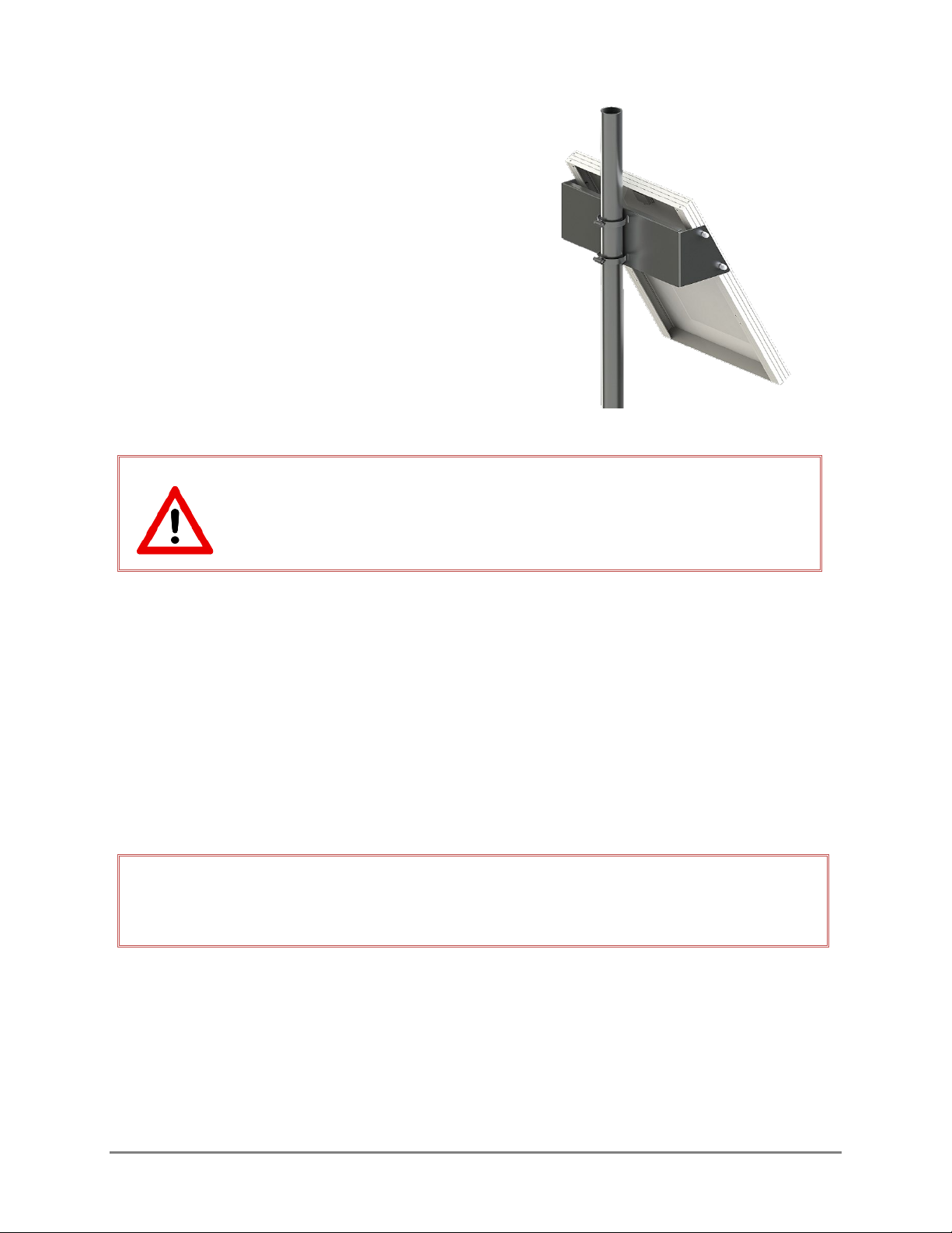
2.4 MOUNTING THE SOLAR PANEL................................................................................................................ 5
2.5 GROUNDING THE SYSTEM........................................................................................................................ 6
2.6 INSERT CABLES........................................................................................................................................... 7
2.7 TELEMETRY ................................................................................................................................................. 8
2.7.1 LT1-CELL SYSTEMS ........................................................................................................................... 8
2.7.2 LT1-GOES SYSTEMS.......................................................................................................................... 8
2.8 CONNECTING SENSORS............................................................................................................................ 8
2.9 POWER CONNECTIONS ........................................................................................................................... 10
2.10 LED STATUS INDICATORS ....................................................................................................................... 13
2.10.1 START UP ......................................................................................................................................... 13
2.10.2 LOW POWER MODE: ...................................................................................................................... 13
2.11 SOLAR REGULATOR STATUS LEDS ......................................................................................................... 14
CHAPTER 3 CONFIGURING WITH THE FTS360 CONFIG APP .......................... 15
3.1 CONFIGURING SENSORS ........................................................................................................................ 15
3.2 CONFIGURE GOES/EUMETSAT STATION SETTINGS/MESSAGE........................................................... 17
3.3 SYNCHRONIZE AND DISCONNECT......................................................................................................... 18
APPENDIX A TROUBLESHOOTING...................................................................... 20
DOCUMENT REVISION HISTORY ............................................................................... 22

700- LT1-Man Rev222 Oct 2018 Page 1/22
DESCRIPTIONChapter 1
1.1 GENERAL
This guide is meant as a ready reference to set up an LT1 System. Details of all aspects of
station operation can be found on the FTS Support website (http://support.ftsinc.com/) in
the following manuals:
• LT1 (Cell/GOES) Operator’s Manual (700-LT1-Man)
• FTS360 and FTS360 Config App (FCA) User Manual (700-FTS360-Man)
LT1-Cell and LT1-GOES systems are set up exactly the same, with the exception of the
placement of the telemetry antennas. LT1-Cell systems come equipped with a dual
cellular/GPS antenna which is mounted internally; LT1-GOES systems require an externally
mounted satellite antenna and the GPS antenna can be mounted either internally or
externally.
1.2 SYSTEM COMPONENTS
The LT1 System Kits consist of all the required components to mount an LT1 station on an
existing 2” diameter pole assembly. The system will have the specific LT1 Bundle for your
order, depending if it is an LT1- Cell or an LT1-GOES. Prior to assembling, examine the
shipment and confirm all the parts arrived and are undamaged.
LT1-CELL-BNDL/LT1-CELL-VZ-BND
ITEM
PART #
LT1- CELL or LT1-CELL-VZ complete with:
•4 pin power terminal block
•8 pin data terminal block
•4 GB SD Card (inserted)
•Slot Screwdriver
•
Integrated Cellular/GPS antenna
LT1-4PIN
LT1-8PIN
19100
19367
18682
OPTIONAL: SIM card (inserted) with purchase of FTS cellular plan
LT1-GOES-BNDL/LT1-GOES-GPS-BNDL
LT1-GOES complete with:
•4 pin power terminal block
•8 pin data terminal block
•4 GB SD Card (inserted)
•Slot screwdriver
•SMA to N adapter*
•SMA plug to SMA jack cable
•SMA plug to N plug cable
•GPS antenna (LT1-GOES-GPS-BNDL only)
LT1-4PIN
LT1-8PIN
19100
19637
20180
19930
19931
GPS-ANTENNA-WP
* Not required if using part# 19931 with integrated SMA to N adaptor

700- LT1-SYS-IG Rev 222 Oct 2018 Page 2/22
LT1-CELL-BNDL and LT1-GOES-BNDL COMPONENTS
The following components are common to Cellular and GOES systems.
LT1-ENCLOSURE-BNDL
ITEM
PART #
Enclosure complete with:
•mounting brackets kit
•LT1 Ground Cable 1(attached in enclosure)
•
LT1 Ground Cable 2 (attached outside of enclosure)
19478
19465
19484
•2 x LT1 Pole Mount Brackets with mounting hardware
•2 x U-Bolts with mounting hardware
•2ft SMA to SMA cable with built-in gland
•15ft SMA to N cable with built-in gland
19480
11597
19930 (GOES only)
19931 (GOES only)
11597 x 2
x 4
19480 x 2
LT1-CELL or
LT1-GOES
19637
LT1-4PIN
LT1-8PIN
18682
(CELL only)
SD
19100
20180
(GOES only)
GPS-ANTENNA-WP
(GOES-GPS-BNDL only)
19930 (GOES only)
19931 (GOES only)
Enclosure
(19478)

700- LT1-SYS-IG Rev 222 Oct 2018 Page 3/22
SOLAR-PANEL-BNDL
ITEM
PART #
20W solar panel complete with:
•Mounting bracket
•Hose clamps (x2)
12221
12196
11117
1.3 POLE MOUNT
The LT1 System comes with fittings so that it can be mounted on a secure vertical pole with
a 2” outer diameter. FTS recommends a 1.5”nominal (1.9” outer diameter) schedule 40 or
80 aluminum pipe.
1.4 REQUIRED TOOLS AND EQUIPMENT
The following tools are required to mount the LT1 System on a pole mount:
¼” flathead screwdriver
#3 Phillips screwdriver
6/8” wrench (or adjustable)
¼” wrench
5/16” socket wrench
Voltmeter
Cable ties
Tools and equipment as required to install pole assembly (if not already installed), mount
antennas, and install the earth ground system.
9AH-BATTERY-BNDL
SOLAR-REGULATOR-BNDL
ITEM
PART #
ITEM
PART #
12 Volt 9Ah battery
LT1 Regulator to battery cable assembly
19833
19466
Solar Regulator
LT1 to regulator cable assembly
19472
19467
12221
121961
11117
19467
19472
19833
19466

700- LT1-SYS-IG Rev 222 Oct 2018 Page 4/22
SETTING UP AN LT1 STATIONChapter 2
2.1 PRIOR TO PROCEEDING TO THE FIELD
IMPORTANT! Prior to proceeding to the field the following MUST be completed
THE ADMINISTRATOR MUST:
Initialize FTS360 (https://360.ftsinc.com/signup or login if FTS initialized FTS360 on
your behalf)
Create a Technician account for the field technician
Ensure any SDI-12 sensors to be added in the field exist in the sensor library (either
default or custom sensor)
THE FIELD TECHNICIAN MUST:
Be invited to Join FTS360 by Administrator
Download the FCA onto the smart device that will be used in the field (available in the
Apple App Store or Google Play. Search for FTS360Config)
CELL only: Provision the SIM card).. Ensure the APN for the SIM card is entered (Go to
the FTS Config App’s dashboard and select “Cellular”)
Test the LT1*
Log onto the FTS360 Config App, synchronize with FTS360. DO NOT LOGOUT
Ensure the SD Card and, for cellular units, the provisioned SIM card and are inserted
Ensure any SDI-12 sensors to be added in the field exist in the sensor library
Bring the required tools (see section 1.4)
* Details of testing the LT1 are found in the LT1 User’s Manual (700-LT1-Man)
2.2 SITE SELECTION
Select a site which allows for installation of the supporting structure which is oriented so
that the solar panel will have maximum sun exposure and antennas will not be blocked by
geographical features, excessive tree canopy, or other obstructions.

700- LT1-SYS-IG Rev 222 Oct 2018 Page 5/22
2.3 MOUNTING THE ENCLOSURE
1) Attach the mounting brackets to the back of the enclosure using the smaller size
bolts in the mounting bracket kit (10-32 x .375 bolts).
2) Attach the top and bottom pole mounting brackets to the enclosure mounting
brackets using the hex bolts. Place a flat washer on the hex bolt, thread through the
enclosure’s mounting bracket and finish with another flat washer, split ring washer
and hex nut.
Figure 2-1: Enclosure with (A) mounting brackets and (B) pole mount brackets
3) Position the enclosure on the pole and secure using the U bolts. Place the U bolt
around the pole and through the mounting bracket slots. Place a flat washer, a
split ring washer and either a wingnut or a hex nut on the U-bolt posts and then
tighten.
4) Place the battery in the enclosure with the posts at the bottom and secure it in place
with the strap.
2.4 MOUNTING THE SOLAR PANEL
Select a position in which the solar panel will have maximum sun exposure throughout the
day. Try to install your solar panel so that nothing casts a shadow on it during any portion
of the day. Consider sun position and length of shadows in all seasons. Even a small
shadow cast by a guy line or small branch can affect the efficiency of the solar panel.
A
B

700- LT1-SYS-IG Rev 222 Oct 2018 Page 6/22
Position the solar panel on the pole and secure with
the clamps.
DO NOT ATTACH THE SOLAR PANEL CABLE TO THE REGULATOR AT THIS
TIME!
Electrical connections to the regulator should be done in the correct
sequence to prevent any damage to the system.
2.5 GROUNDING THE SYSTEM
An external earth ground wire MUST be attached between the earth grounding system and
the LT1 SYSTEM to provide protection from lightning and other electrostatic discharge.
Be aware that the composition of the substrate directly affects the efficiency of the earth
ground; areas with a low conductive substrate such as rock, sand, ice may require more
than one grounding rod.
IMPORTANT! FTS recommends that you consult a qualified professional to ensure
adequate earth ground protection is installed for the site and that all local regulations
are met.
Set up the earth-ground system and secure the free eye of the LT1 Ground Cable 2 to the
grounding system.

700- LT1-SYS-IG Rev 222 Oct 2018 Page 7/22
2.6 INSERT CABLES
The first step in setting up the internal enclosure components is to feed all cables through
the enclosure glands. Unscrew the bottom gland cap and remove the plug. It is
recommended to store the plugs in a small bag inside the enclosure so if a cable is
removed, the gland can be restored to its sealed state to maintain the IP rating of the
enclosure.
Figure 2-2: Inserting cables
Feed sensor cables and the solar panel cable through a gland cap and then through the
gland into the enclosure. Replace the gland cap, ensuring it is tightly screwed on to form a
seal.
For LT1-GOES systems, the fitted gland on the SMA to N cable for the satellite antenna and
the SMA to SMA jack cable (if using an externally mounted GPS antenna) replaces the
enclosure gland. Remove an enclosure gland by unscrewing the internal nut (the 5/8”
wrench may be required to initially loosen the nut). Remove the nut on the cable’s gland
and feed the cable and gland fitting through the bottom of the enclosure. Replace and
tighten the nut.
Figure 2-3: Gland replacement and inserted cables – externally mounted GPS
Removing the gland plug
Recommended cable placement
Satellite
Sensors
Solar Panel
External GPS

700- LT1-SYS-IG Rev 222 Oct 2018 Page 8/22
2.7 TELEMETRY
2.7.1 LT1-CELL SYSTEMS
1)
Uncoil sufficient cable for the dual GPS/cellular
antenna to reach from the platform to the
connectors on the LT1. Place the dual antenna
on the platform and secure in place with the split
nut.
2)
Attach the GPS and Cell cables to the
appropriate jack on the LT1.
3)
Remove the terminal blocks from the LT1 (for
ease of making power and sensors connections)
and mount the LT1 on the left hand side of the
DIN rail.
Figure 2-4
2.7.2 LT1-GOES SYSTEMS
1) Mount the satellite and GPS antennas in their desired locations. The GPS antenna can
be mounted on the enclosure’s antenna platform if its design permits.
2) Attach the satellite antenna and GPS antenna cables to their respective jack on the LT1.
3) Remove the terminal blocks from the LT1 (for ease of making power and sensors
connections), and mount the LT1 on the left hand side of the DIN rail.
2.8 CONNECTING SENSORS
Sensors are connected via the 8 pin data terminal block (refer to Figure 2-5 for wiring
guidance). The LT1 can accommodate one NMEA device, two SDI-12 sensors, and a rain
gauge. If two SDI-12 sensors are being connected, they must have their wires spliced and
use the same pins designated for SDI-12 sensors. Additionally, if more than two devices
are being connected, a ground terminal will have to be shared.
Once sensors are connected to the 8 pin terminal block it can be inserted into the LT1.
Dual Antenna
Solar panel
cable
Sensor cable

700- LT1-SYS-IG Rev 222 Oct 2018 Page 9/22
CONNECTING SDI-12 SENSORS
Connect the SDI-12 power wire (+) to the SP pin, the SDI-12 data wire to the SD
pin, and the ground wire to either the GD or the Gpin.
CONNECTING A TIPPING BUCKET (RAIN GAUGE)
Connect the signal input wire to the RN pin, and the ground wire to either the GD
or the Gpin.
FT742 RS-485 WIND SENSOR HEATER OPTION
If using the heater option on an attached FT742 RS-485 wind sensor a power
source capable of at least 3 A must be attached to both the PW and HT pins.
Details of connecting an FT7X2 RS-485 wind sensor are found in App Note 162
(700-AN-162) and posted to the FTS Support site.
Figure 2-5: 8 Pin Terminal Block Wiring Guide
B
RS485/NMEA negative
A
RS485/NMEA positive
G
Signal ground
SD
SDI-12 data
SP
SDI-12 power out
GD
Power ground
RN
Discrete counter in
(Rain Gauge)
P
RS485/NMEA power out

700- LT1-SYS-IG Rev 222 Oct 2018 Page 10/22
2.9 POWER CONNECTIONS
The LT1 SYSTEM is powered through a battery which maintains its charge through a solar
panel and regulator. Refer to the following diagram for pin locations when connecting
devices to the solar regulator.
IMPORTANT!
Power connections must be made in
the order indicated to prevent
damage to the station and
equipment.
Figure 2-6: Solar regulator pin diagram
STEP 1: MAKE SOLAR CHARGE REGULATOR CONNECTIONS
1) Remove the cap and plug from one of the enclosure ports. Feed approximately 10
inches of the solar panel cable through an access port. Once all connections are made
excess cable can be fed back through the port and the cap secured.
2) Remove the LT1 Power Terminal Block from the LT1. Once all connections are made,
the terminal block will be inserted into the terminal port to complete the cycle. Make
the following connections with the LT1 to Regulator Cable Assembly:
(to enclosure
grounding post)
Black wire to terminal 1 (GND)
Red wire to terminal 2 or 3 (OUT)
LT1 Ground Cable to the CG pin
Black wire to G pin
Red wire to PW pin

700- LT1-SYS-IG Rev 222 Oct 2018 Page 11/22
3) Connect the leads from the solar panel to the regulator as follows:
4) Connect the LT1 Regulator to battery cable assembly (part # 19466) to the solar
regulator as follows:
5) Mount the solar regulator onto the DIN rail beside the the LT1 and secure the battery in
position using the red Velcro strap.
HINT:
To attach and release the solar regulator,
slide a small screwdriver into the bottom latch
to unlock and lever up or down accordingly.
STEP 2: CONNECT POWER
1) Connect the LT1 Regulator to battery cable assembly (part # 19466) to the battery as
follows:
WARNING! Damage to the regulator can result if you do not connect
these wires in the correct order or with the proper polarity!
Release
Attach
Unlock
Black wire (-) to terminal 7 (GND)
Red wire (+) to terminal 9 (BAT)
To battery
Black wire to terminal 10 (GND)
Clear wire to terminal 11 or12

700- LT1-SYS-IG Rev 222 Oct 2018 Page 12/22
a) First, connect the black wire to the battery’s negative (-) terminal.
b) Second, connect the red wire to the battery’s positive (+) terminal.
The solar regulator LEDs will power up and display green lights. Refer to section 2.7 for
details of the solar regulator LED status indicators.
Use the reverse order to disconnect the battery.
2) Use the voltmeter to confirm 12 volts is being supplied to the output terminal on which
the LT1 to Regulator Cable Assembly is attached (regulator terminal 2 or 3)
IMPORTANT! Prior to connecting the LT1, the output from the solar regulator
MUST be disabled.
3) Press and hold the button on the regulator for at least 3 seconds. The output LED
should turn off and blink on every 2 seconds.
Figure 2-7: Solar Regulator status LEDs and final power connections (LT1-CELL shown)
4) Insert the terminal block into the LT1.
5) Turn on the regulator output by quickly pressing the black button on the regulator.
Ensure the Output LED on the solar regulator turns solid On and the LT1 LEDs indicate
there is power.
Press for 3 seconds to disable
output
Quickly press and release to
enable output

700- LT1-SYS-IG Rev 222 Oct 2018 Page 13/22
2.10 LED STATUS INDICATORS
Once power is supplied, the LT1 will boot up, and establish a GPS fix. The green LEDs
indicate the status of the system.
2.10.1 START UP
When power is first supplied or someone connects to the station:
System
Status
Blinking every second: System OK
Off: System powered down/failure
Telemetry
Status
Solid On: System OK
•Cellular: module powered and communicating to MCU*,
cellular link established
•GOES: transmitter enabled and valid configuration
Blinking: Cell: Obtaining network connection
GOES: no GPS fix/potential invalid configuration
Off: System powered down/no link/fault
BLE
Status
Solid On: BLE connection established
Blinking: System OK (module powered and communicating to
MCU*, module broadcasting beacon signal)
Off: system powered down/no beacon signal transmission/fault
GPS
Status
Solid On: System OK (module powered and communicating to
MCU*, fix established)
Blinking: Obtaining GPS fix
Off: System powered down/fault
*MCU= microcontroller unit
2.10.2 LOW POWER MODE:
Three minutes after being disconnected from the FTS360 Config App, the unit will enter low
power mode:
System
Status
Blinks once every 10
seconds: System OK NOTE: When in low power mode, a fault is
not indicated if the Telemetry, BLE and GPS
status lights are off. If you suspect a fault,
use the FTS360 Config App to connect to
the station and observe the LEDs.
Telemetry
Status
Off
BLE
Status
Off
GPS
Status
Off

700- LT1-SYS-IG Rev 222 Oct 2018 Page 14/22
2.11 SOLAR REGULATOR STATUS LEDS
Once the power loop is complete, the solar regulator LEDs will light to indicate the status.
The Solar, Battery, and Output LEDs are green and are associated with the solar panel
input, battery input and output. The Error LED is red.
Once power is supplied to the regulator, the LEDs will display for 15 seconds and then turn
off (power saving mode). To review the status LEDs, press the black button.
SOLAR REGULATOR STANDARD LED STATUS INDICATORS
DESCRIPTION
SOLAR
BATTERY
OUTPUT
ERROR
Solar panel
connected On - - -
Battery ready
-
On
-
-
Output turned on
-
-
On
-
Output disabled
(can be turned on)
- - Off– blinks on every 2s -
Battery charging
-
On-blinks off every 2s
-
-
Battery discharging
-
Off-blinks on every 2s
-
-

700- LT1-SYS-IG Rev 222 Oct 2018 Page 15/22
CONFIGURING WITH THE FTS360 CONFIG APPChapter 3
Detailed information on FTS360 and the FTS360 Config App can be found in the FTS360
User Manual (700-FTS360-Man)
3.1 CONFIGURING SENSORS
Once connected to the LT1 and powered, use the FTS360 Config App to add and configure
the sensor for the station.
1) Connect to Station
•Open the FTS360 Config App. It should automatically discover the Station. If the
station is not discovered, press the “Scan” bar.
The first time a station is connected to the FTS360 Config App, it’s identified by its serial
number. Any configuration which happens in the field will be saved to that station.
Once synchronization happens, the station’s name can be changed from the serial
number to a user friendly name using the station edit function in FTS360 or the FTS360
Config App.
•Select “Connect” to display the Station Dashboard (the BLE Status light on the LT1 will
become solid “On” when connectivity established). If there are several stations
discovered, ensure you connect to the correct one.
HINT: If there is more than one LT1 station in the area, once connected,
select the Flash LEDs bar to confirm you are connected to the desired
station.

700- LT1-SYS-IG Rev 222 Oct 2018 Page 16/22
2). Add and configure sensors: Select the sensor type to add (NMEA or Rain). To add an
SDI-12 sensor, select the Add Sensor bar.
3). Test the sensor(s): Select the Test Sensor bar. This will trigger a reading by the sensor
and the data point(s) will display.
NOTE: New sensors should always be tested prior to leaving the site to ensure they
are operating as desired.
This will indicate GOES or
Cellular as per the LT1 type
It can take up to 20
minutes to get a GPS fix
Select the desired
sensor from the Sensor
Type drop down list and
edit fields as necessary.
Save.
HINT:
Custom library items created
by your agency are listed first,
followed by default library items.
Use the Search feature to find a
specific entry or to filter the items by
sensor type

700- LT1-SYS-IG Rev 222 Oct 2018 Page 17/22
3.2 CONFIGURE GOES/EUMETSAT STATION SETTINGS/MESSAGE
GOES/EUMETSAT stations must have the telemetry and message format configured
1) Select the arrow on the GOES line to open the Station GOES Settings screen. Fill in the
fields with your provided satellite information.
2) To configure the message, select the
Configure Transmitted Message bar and use
the drop down menu to select the data
format type.
NOTE: information on this sample
screen is for demonstration
purposes only:
Once all fields are
completed, the
Transmission Enabled
button will be displayed
Other manuals for LT1
1
Table of contents
Other FTS Measuring Instrument manuals