SATAM ZC 17-24 Owner's manual

SATAM Siège Social : Paris Nord II – Bât. Le Gauguin – 47, allée des Impressionnistes
Usine de Falaise – Avenue de Verdun – B.P. 129 – 14700 FALAISE – France B.P. 85012 – Villepinte – 95931 Roissy C.D.G. Cedex - France
Tél. : +33 (0)2 31 41 41 41 Tél. : +33 (0)1 48 63 02 11
Fax : +33 (0)2 31 40 75 61 Fax : +33 (0)1 49 38 41 01
SIRET 495 233 124 000 17 SA au capital de 6 037 000 € – RCS Bobigny B 495 233 124
CODE APE 2813 Z SIRET 495 233 124 000 17 – Code APE 2813 Z – N°TVA : FR 48 495 233 124
MEASURING CHAMBERS – ZC 17-
24
and ZC 17-48 METERS
--
Description – Installation – Operation – Servicing
U508113-e– Révision 4 – 29 March 2012
This document consists of 16 pages, (including the flyleaf)
This document is the property of SATAM
And can’t be transmitted to someone also with out prior authorisation
SATAM may modify this document without prior notice
In conformity with the European directive 94/9/CE-ATEX

Edition du 29/03/12 2/16 U508113-e Révision 4
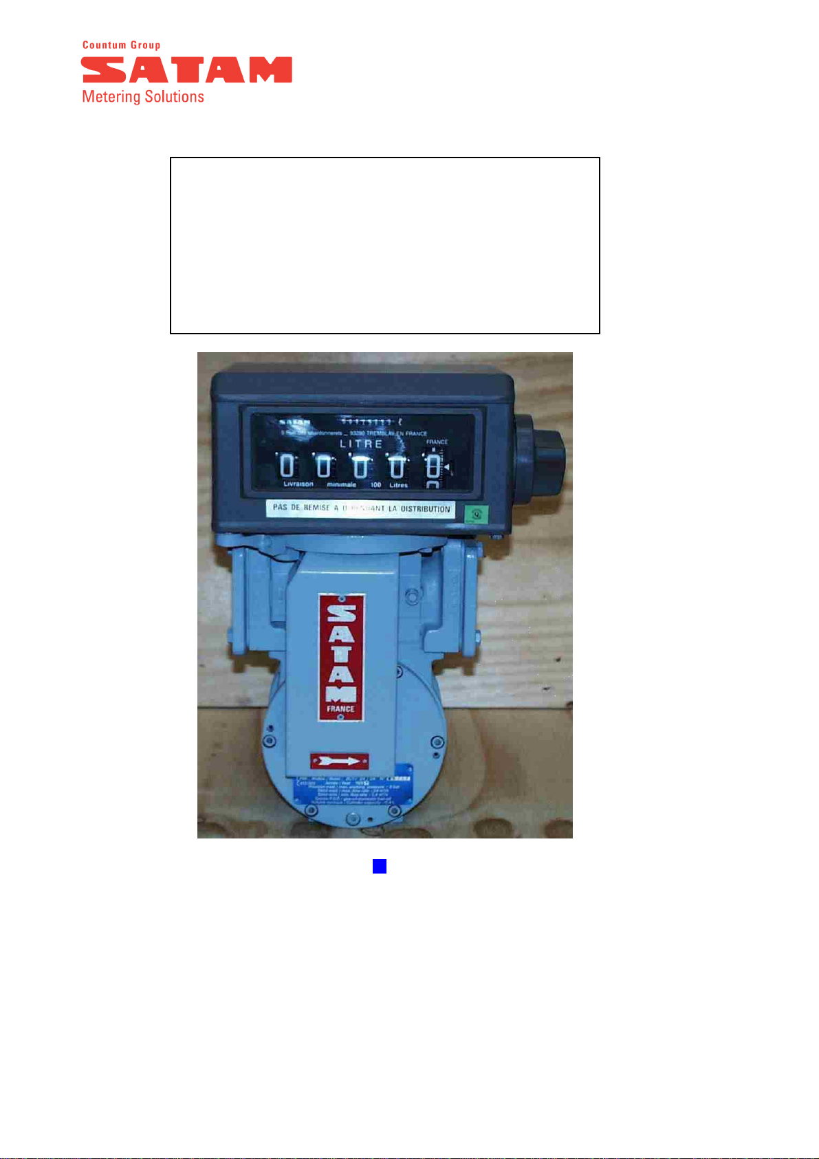
MEASURING CHAMBERS – ZC 17-24 and ZC 17-48 METERS
SUMMARY
1.
GENERAL .....................................................................................................................................................3
2.
RECEPTION..................................................................................................................................................3
3.
OPERATING PRINCIPLE..........................................................................................................................3
4.
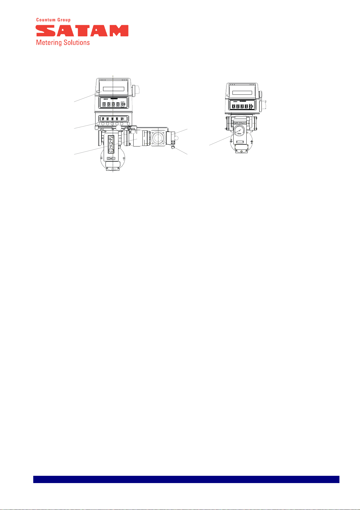
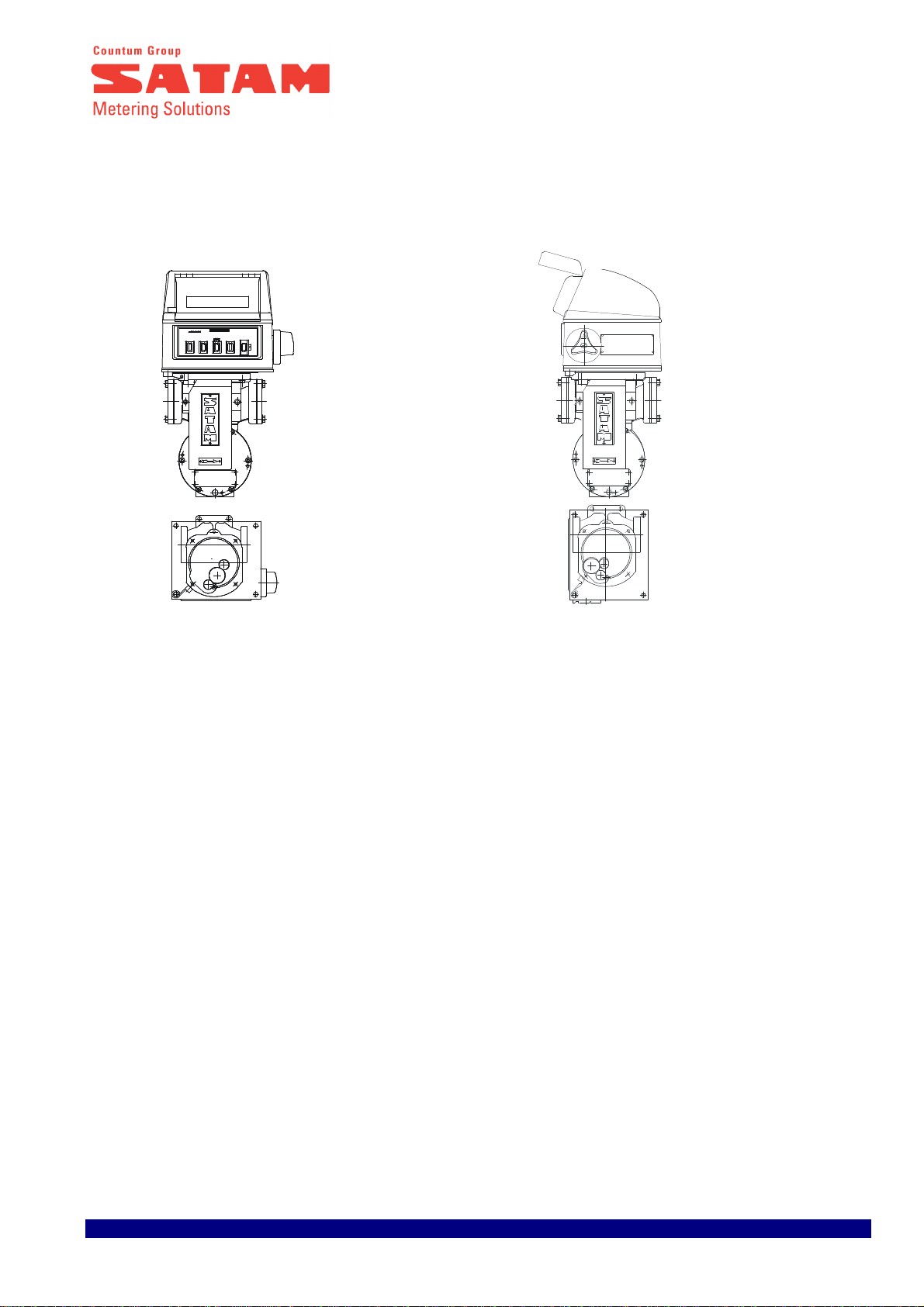
COMPONENTS.............................................................................................................................................4
5.
DESCRIPTION..............................................................................................................................................6
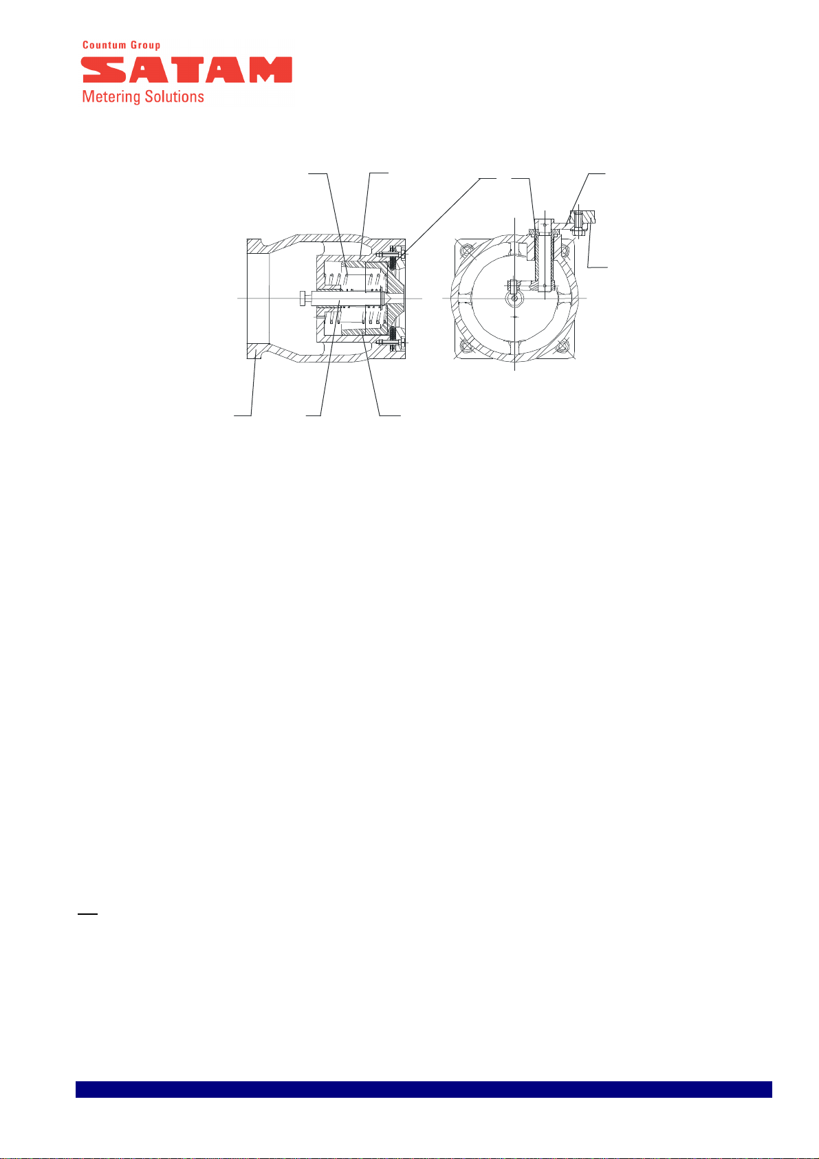
5.1.
Blade-type positive displacement measuring chamber............................................................................6
5.2.
A manifold................................................................................................................................................7
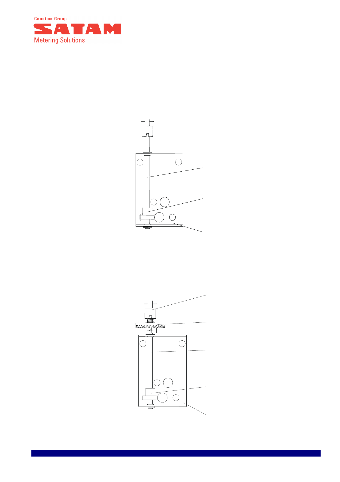
5.3.
A transmission system..............................................................................................................................8
5.4.
AB 35 Calibrating mechanism.................................................................................................................9
5.5.
Preset with XAD 39 mechanical Preset valve........................................................................................10
5.6.
Preset with XAD 54 pneumatic Preset valve..........................................................................................10
5.7.
Three way valve.....................................................................................................................................10
6.
INSTALLATION.........................................................................................................................................11
7.
OPERATION...............................................................................................................................................11
7.1.
Preset Operation....................................................................................................................................11
7.2.
Checking low flow initiation..................................................................................................................11
7.3.
3 ways valve operation ..........................................................................................................................12
8.
METROLOGICAL INSPECTION MEASURING CHAMBER............................................................13
8.1.
General..................................................................................................................................................13
8.2.
Adjustment Procedure for mechanical meter head................................................................................13
9.
PERIODIC SERVICING............................................................................................................................15
9.1.
General..................................................................................................................................................15
9.2.
Monthly Periodic Inspections................................................................................................................15
9.2.1.
Strainer Baskets .............................................................................................................................15
9.2.2.
MA 21 Measuring Chamber ..........................................................................................................15
9.2.3.
Ticket Printer .................................................................................................................................15
9.3.
Yearly Inspection ...................................................................................................................................15
9.3.1.
MA 21 Measuring Chamber ..........................................................................................................15
9.4.
Meter Head............................................................................................................................................16
9.5.
REMARK VERY IMPORTANT ..............................................................................................................16

Edition du 29/03/12 3/16 U508113-e Révision 4
1. General
This chapter contains information relating to the reception and assembly of the ZC 17-24 and ZC 17- 48
METERS.
2. Reception
The meters are packed in cardboard packing designed for and adapted to protect the meters during transport.
However if, on arrival, the packaging appears to have been damaged, the customer should notify the carrier of
the damage and inform SATAM.
3. Operating Principle
The liquid enters the metering unit in the direction indicated by the arrows (A). The rotor assembly is set in motion
under the pressure of the liquid on the blades (3). A certain amount of liquid (5) is captured between two
consecutive blades, and measured on the part of the circular way corresponding to the biggest of the 2 radii of the
stator, and then pushed towards the outlet manifold (B). The quantity of liquid measured at each revolution (i.e.
the cyclical volume) is therefore equal to four times the quantity measured.
Accuracy is obtained through the very small clearance between the rotor (2) and the stator (1), the blades (3) and
the covers.
The curved design of the manifolds and rotor ensures a steady, non-fluctuating flow of product, resulting in very
small head loss. The rotor is supported on stainless steel bearings.
A transmission system mounted on the front of the measuring chamber transmits the rotor’s movement to a
steeple calibrating mechanism enabling meter adjustment without gear replacement. The meter register is
mounted on the calibrating mechanism.

Edition du 29/03/12 4/16 U508113-e Révision 4
Cell with the shape in the axis of the body
Cell with the shape in 45 °of the
axis of the
body
4. Components
After removing the meter from its packaging, you will find it is composed of the following elements :
➥
➥➥
➥Standard Meter
- Positive displacement measuring chamber (1)
- Transmission system (2)
- Calibrating mechanism model AB 35 (3)
- A meter head (4) mechanics or electronics
reading in litter or gallons, according to the customer requirement.
- The transmission system (2) and the calibrating mechanism AB35 (3) are replaced by a pulser, for meter using
an electronic calculator.
LITRE
LITRE
jauge
4
1
3
2
4
1
3
2
5
A B
3
A

Edition du 29/03/12 5/16 U508113-e Révision 4
➥
➥➥
➥A wide range of accessories
- Ticket printer (1) : accumulative model or 0-start model
- A preset (2) with main valve type XAD 39 (3) with mechanical actuator or XAD 54 with pneumatic actuator
- A 3-way-Valve (4) equipped with its valve box (5)
- A rate of flow indicator reading in l/min, m3/h.(6)
S
T
O
P
S
E
T
LITRE
LITRE
3
M/h
55
50
45
40
35
30
25
15
10
5
0
20
1
2
3
4
5
6

Edition du 29/03/12 6/16 U508113-e Révision 4
5. Description
5.1. Blade-type positive displacement measuring chamber
Measuring apparatus with fixed lids
Measuring apparatus with centered lids
The measuring chamber consists of :
a body (1) in ni-resist cast iron or aluminum IN AC-42200 S T6 (HAVE 7G 06 Y23), made up of 2 cylindrical parts
(2) and (3) of different radii, connected via curves in such a way that the sum of the distances from center point 0
to two points opposite each other on the stator is constant.
A moving part (4) composed of :
. A rotor (5) turning on stainless steel ball bearings (6)
. Graphite blades (7) linked to each other by rods (8)
. 2 steel covers (9) and (10) ( Fixed or centered)
. A seal O’ring (11) for the shaft.
10
6
9
8
4
11
A-A B-B
5 Centre o7
3
2
1
9
10
5

Edition du 29/03/12 7/16 U508113-e Révision 4
5.2. A manifold
An aluminium manifold is mounted on the measuring chamber. The position of the gears differs according to the
position of the register.
Position 2
Position 1

Edition du 29/03/12 8/16 U508113-e Révision 4
5.3. A transmission system for mechanical indicator
The transmission system forms the link between the measuring chamber and the calibrating mechanism. Two
different types of system are available :
standard system consisting of :
- a housing (1)
- a drive axle (2)
- a measuring chamber outlet gear (3)
- a transmission(4)
a system designed to receive a "Instantaneous Flow Rate" consisting of :
- a housing (1)
- a drive axle (2)
- a measuring chamber outlet gear (3)
- a drive gear to drive the "Instantaneous Flow Rate" (5)
- a transmission (4)
4
2
3
1
1
4
5
2
3

Edition du 29/03/12 9/16 U508113-e Révision 4
5.4. AB 35 Calibrating mechanism for mechanical indicator
The AB 35 calibrating mechanism is located at the outlet of the transmission device.
The movement of the measuring chamber drives the transmission device gear via the endless screw. At the end
of the transmission device, a drive shaft links to the AB 35 calibrating mechanism.
Operation :
Meter movement is transmitted via the inlet shaft (1) to the outlet shaft (2) by a wheel (3). This inlet shaft (1)
drives an eccentric hub (4) which, via the disk (5) and a second wheel (6), drives the outlet shaft (2) faster at
certain parts of the cycle.
The position of the hub (4) can be adjusted using an adjustment screw (7). Each notch of the screw equals a
correction of 0.25‰ , whatever the direction of adjustment. Maximum 40 ‰.
1
7
6
2
6
5
3
4

Edition du 29/03/12 10/16 U508113-e Révision 4
5.5. Preset with XAD 39 mechanical Preset valve
A cam assembled on the lower part of the preset controls a shaft which opens or closes the preset valve .
The Preset valve consists of the following elements :
An outer casing in aluminium (1)
A moving needle (2)
A mobile part consisting of a piston (3), a gasket (4) which slides within the chamber
A spring (5) maintaining the moving part on its seat (6)
A drive system consisting of a guide (7), a control lever (8) and an eccentric (9).
5.6. Preset with XAD 54 pneumatic Preset valve
See Installation, Operation and maintenance manual Ref.U516120
5.7. Three way valve
Fitted at the meter outlet, the 3-way-valve allows measured distribution through two different pipes in condition to
assure the security of a precise measure for one or the other of the pipes.
Description
The 3 way valve is a ball-valve. Its body forms a 90° elbow which turns on its inlet shaft.
A control lever enables the selection of one outlet or the other, by rotating 180°through a neutral p osition of
complete closure. This means that the two outlets never come into contact with one another.
A locking system linked to the meter head (register and ticket printer) prevents the control lever from rotating
more that half its possible movement when the printer is blocked and the register is being reset.
NB
The locking system therefore prevents liquid flow via the outlet that has not been selected, and prevents any
modification in the position of the valve during distribution.
For this, the 3-way-valve is linked to the measuring chamber and the meter head (register and printer) by a
mechanical linkage and is sealed by the appropriate Weights and Measures seal.
5 4 6 7 8
9
3
21

Edition du 29/03/12 11/16 U508113-e Révision 4
6. Installation
All meters should be protected upstream by a strainer;
Filtration for Gasoline, Premium, Super, Jet A1 : 200 microns
Filtration for diesel oil, gas oil, FOD : 450 microns
Counter flanges to be welded are supplied with the meter to enable the user to connect the meter to a 2”
horizontal installation (Ø 60.3).
7. Operation
Once the hydraulic and electrical installation has been completed, the meter may be put into operation.
To ensure this is carried out under optimal conditions, the following points should be strictly adhered to :
- use clean product, devoid of any metallic particles
- all piping should be clean, rinsed, and completely dry.
7.1. Preset Operation
➥To display preset quantity required :
Stand in front of the preset. Press the “Set” button on the left to unlock the preset, then press each of the 5 push
buttons until the quantity required is displayed in the windows. The quantity is indicated in litres. For emergency
stop, press the right hand “Stop” button.
➥To open the Preset Valve :
Pull the control lever towards yourself
7.2. Checking low flow initiation
For a ZC 17-24 or a 48 meter, low flow is initiated at approximately 30 litres from the end of delivery (transfer from
high to low flow at 30 litres from end of loading).
Low flow setting
- Remove the cover (1)
- Adjust the setting by changing the position of the roller using the 19 mm flat spanner and a 10 mm spanner.
- Rotate the eccentric in a clockwise direction to increase the low flow rate
- Rotate the eccentric in an anticlockwise direction to reduce low flow rate
- A non closing of the valve can be due to a too low set up of the low flow rate
- In stop state, there must be a clearance between the roller and the cam
+
-
45°
Position Petit Débit
1
er
Cran d’ornement
1
Réglage du petit débit par
rotation du galet excentrique
avec une clé extra plate de 19
et une clé plate de 10

Edition du 29/03/12 12/16 U508113-e Révision 4
7.3. 3 ways valve operation
1. Insert a ticket in the ticket printer
2. Choose the outlet pipe required (either via the front (B) or the back (A) of the valve) by using the lever (1).
a) lightly pull the lever (1) and position it in relation to the outlet pipe required (position A or B) and put the
lever (2) in a open position 0.
b) block the ticket printer by turning the meter head button one full turn.
This operation results in :
- The ticket being locked in the printer
- Printout on the ticket of a first line of figures
- Resetting of the figures indicated on the register
- The selected setting of the 3-way-valve being locked
3. Delivery can now take place, or flow rate modified, using the control lever (2) of the 3 ways valve.
At the end of delivery the user turns the meter head push button a full turn which results in :
- A second row of figures being printed on the ticket
- The ticket is released
- The 3 way valve is released.
(without modification of the information display on the register)
The complete cycle can begin again.
F
O
F
O
B
A
1
2

Edition du 29/03/12 13/16 U508113-e Révision 4
8. Metrological Inspection Measuring Chamber
8.1. General
Current DIRRECTE and LNE (Weights and Measures) legislation require :
. Metrological inspection of meter at operation start-up
. Subsequent yearly inspections.
If during gauging the meter is found to be outside the accepted error, it is possible to re-calibrate the meter using
the AB 35 calibrating mechanism. For meters using an electronic calculator, the re-calibration is made by
adjustment of the calculator correction factor (see annex 2 of document U513237 for the RUBIS, U516318 for the
l’EQUALIS L and U516703 for the EQUALIS MPC).
8.2. Adjustment Procedure for mechanical meter head
A. TEST
1. Carry out a test run at the installation's maximum rate of flow using a 500 litres or 1000 litres gauge.
2. Note the volumes indicated on the Register and on the gauge respectively.
Example : 1000 litres at the Register
997 litres at the Gauge
3. Calculate the difference Register reading – Gauge reading. For the above example :
1000 l - 997 l = 3 l
i.e. a difference of +3 litres for 1000 litres = 3‰
B. PRINCIPLE OF ADJUSTMENT
Reminder : 1 notch of the calibration screw (2) = 0.25‰ in whatever direction adjustment is made.
Maximum : 40‰
1. Note the position of the calibrating screw.
2. Turn the screw the appropriate number of notices in the direction required to obtain the required
adjustment :
Difference (in ‰) / 0.25 = number of notches
In the above example, 3 litres must be added to the gauge. Therefore we must turn the calibration screw (2) in
the direction + :
3 ‰ / 0.25 = 12 notches, in an anticlockwise direction.

Edition du 29/03/12 14/16 U508113-e Révision 4
C. ADJUSTMENT OPERATION OF AB 35
1- Unseal and remove the cover (1)
2- Unscrew the two screws (3)
3- Slide the cover down.
4- Carry out adjustment as described above (§B)
5- Check adjustment by carrying out a new gauging test.
6- Put the cover back in place and tighten the screws.
7- Re-seal
D – ADJUSTMENT OF THE ELECTRONIC CALCULATOR RUBIS OR EQUALIS
See calibration instructions U513237 For the Rubis
See calibration instructions U516318
For the Equalis L
See calibration instructions U516703
For the Equalis MPC
3
1
3
2

Edition du 29/03/12 15/16 U508113-e Révision 4
9. Periodic servicing
9.1. General
Periodic maintenance is required at least once a year.
Service operations must be carried out by a Company approved by Weights & Measures.
9.2. Monthly Periodic Inspections
9.2.1. Strainer Baskets
The strainers installed upstream of the meter should be inspected.
N.B Filtration for Gasoline/premium/Jet : 200microns
Filtration for Gas oil, Diesel Oil, Fuel Oil : 450 microns
9.2.2. MA 21 Measuring Chamber
Check that no leakage is occurring around the measuring chamber outlet shaft
9.2.3. Ticket Printer
Make sure there are no particles or pieces of ticket caught in the ticket printer mechanism.
9.3. Yearly Inspection
9.3.1. MA 21 Measuring Chamber
The transmission assembly consisting of wheel (3) and screw (2) on the drive shaft (4) should be cleaned and
greased.
Check clearance between the wheel (3) and the screw (2).
Check the bearings (5 & 6) on shaft (4).
Clean and grease the bearings (5 & 6)
In the upper part of the inlet/outlet manifold (7), check the rings and the drive gear shaft leading to the mechanical
register.
Clean and grease the drive gear assembly in the upper part of the manifold (7).
N.B The AB 35 calibrating mechanism does not require preventive maintenance.

Edition du 29/03/12 16/16 U508113-e Révision 4
9.4. Meter Head
See the Installation and Operation Manual.
9.5. REMARK VERY IMPORTANT
AB35
Take care about the alignment
between axle 1 and the AB 35
entry
EntryAB35
6
4
3
5
2
1
7
We strongly advise against the use of a high pressure water jet to clean the measuring unit,
as this could seriously damage the metering unit.
This manual suits for next models
1
Table of contents
Other SATAM Measuring Instrument manuals
Popular Measuring Instrument manuals by other brands

Toptica
Toptica Digilock 110 manual

Bresser
Bresser RANGEFINDER.800 instruction manual

Kimo
Kimo MP 120 user manual

Simpson
Simpson 444 Operator's manual

Excelitas Technologies
Excelitas Technologies OmniCure LM2011 Series user guide

Motorline professional
Motorline professional BEWEATHER User's and installer's manual