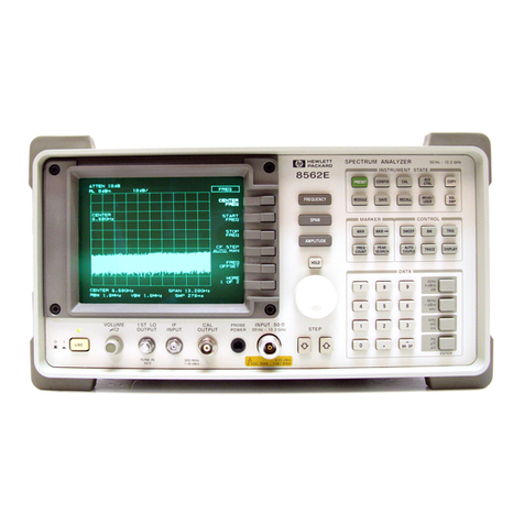
HP 8719A User manual

-~
ARTISAN
®
~I
TECHNOLOGY
GROUP
Your definitive source
for
quality
pre-owned
equipment.
Artisan Technology
Group
Full-service,
independent
repair
center
with
experienced
engineers
and
technicians
on staff.
We
buy
your
excess,
underutilized,
and
idle
equipment
along
with
credit
for
buybacks
and
trade-ins
.
Custom
engineering
so
your
equipment
works
exactly as
you
specify.
•
Critical
and
expedited
services
•
Leasing
/
Rentals/
Demos
• In
stock/
Ready-to-ship
•
!TAR-certified
secure
asset
solutions
Expert
team
ITrust
guarantee
I
100%
satisfaction
All
tr
ademarks,
br
a
nd
names, a
nd
br
a
nd
s a
pp
earing here
in
are
th
e property of
th
e
ir
r
es
pecti
ve
ow
ner
s.
Visit our website - Click HERE

Errata
Title & Document Type: HP 8719A, 8720A/B Microwave Network Analyzer
Service Manual
Manual Part Number: 08720-90108
Revision Date: 1990-09-01
HP References in this Manual
This manual may contain references to HP or Hewlett-Packard. Please note that Hewlett-
Packard's former test and measurement, semiconductor products and chemical analysis
businesses are now part of Agilent Technologies. We have made no changes to this
manual copy. The HP XXXX referred to in this document is now the Agilent XXXX.
For example, model number HP8648A is now model number Agilent 8648A.
About this Manual
We’ve added this manual to the Agilent website in an effort to help you support your
product. This manual provides the best information we could find. It may be incomplete
or contain dated information, and the scan quality may not be ideal. If we find a better
copy in the future, we will add it to the Agilent website.
Support for Your Product
Agilent no longer sells or supports this product. You will find any other available
product information on the Agilent Test & Measurement website:
www.tm.agilent.com
Search for the model number of this product, and the resulting product page will guide
you to any available information. Our service centers may be able to perform calibration
if no repair parts are needed, but no other support from Agilent is available.
Artisan Scientific - Quality Instrumentation ... Guaranteed | (888) 88-SOURCE | www.artisan-scientific.com
MICROWAVE
NETWORK ANALYZER
SERVICE MANUAL
SERIAL
NUMBERS
This manualapplies directlyto network analyzers with these
serialnumber prefixes:
HP
8719A: 3029A
HP
8720A: 2914A
HP
87208: 3029A
For additional information,see
Instrument
History
section of
this manual.
@Copyright HEWLElT-PACKARD COMPANY 1989
1400FOUNTAINGROVEPARKWAY,SANTA ROSA, CA 95403 U.S.A.
MANUALPART NO. 08720-90108
MicrofichePart Number 08720-90106 Printed: SEPTEMBER 1990
Artisan Scientific - Quality Instrumentation ... Guaranteed | (888) 88-SOURCE | www.artisan-scientific.com

CERTIFICATION
Hewlett-PackardCompany certifiesthatthisproductmetitspublishedspecificationsatthetimeofshipmentfrom
the factory. Hewlett-Packardfurther certifiesthatitscalibrationmeasurementsare traceableto the UnitedStates
NationalInstituteof Standards and Technology (NIST, formerly NBS), to the extent allowed by the Institute's
calibrationfacility, andto the calibrationfacilities of other InternationalStandardsOrganizationmembers.
WARRANTY
This Hewlett-Packardsystem product iswarranted againstdefects inmaterialsandworkmanshipfor a period
corresponding to the individual warranty periods of its component products. Computer and computer
peripheralsarewarrantedfor aperiodof
90
days.Instrumentsarewarrantedfor aperiodof oneyear. Duringthe
warrantyperiod,Hewlett-PackardCompanywill,at itsoption,eitherrepairorreplaceproductswhichprovetobe
defective.
Warranty servicefor products installedby HPandcertainotherproductsdesignatedby HPwill beperformedat
Buyer'sfacilityatnochargewithin HPservicetravelareas.OutsideHPservicetravelareas,warrantyservicewill'
be performed at Buyer's facility only upon HP's prior agreement and Buyer shall pay HP's round trip travel
expenses. Inall other areas, products must
be
returnedto a service facilitydesignatedby HP.
Forproductsreturnedto HPfor warranty service,Buyershall prepayshippingchargesto HPand HPshallpay
shipping charges to returnthe product to Buyer.However,Buyer shall pay all shipping charges, duties, and
taxes for products returnedto HP from another country.
HP warrants that its software and firmware designated by HP for use with an instrument will execute its
programminginstructionswhenproperly installedonthatinstrument.HPdoesnotwarrantthattheoperationof
the instrument,or software, or firmware will
be
uninterruptedor error free.
LIMITATIONOF
WARRANTY
Theforegoingwarrantyshallnotapplytodefects resultingfrom improperor inadequatemaintenanceby Buyer,
Buyer-suppliedsoftware orinterfacing,unauthorizedmodificationor misuse,operationoutsideof the environ-
mentalspecificationsfor the product, or improper site preparationor maintenance.
NO OTHER WARRANTY IS EXPRESSEDOR IMPLIED. HP SPECIFICALLY DISCLAIMSTHE IMPLIEDWAR-
RANTIESOR MERCHANTABILITYAND FITNESSFOR A PARTICULARPURPOSE.
EXCLUSIVEREMEDIES
THE REMEDIESPROVIDEDHEREINARE BUYER'SSOLE AND EXCLUSIVEREMEDIES. HP SHALL NOT BE
LIABLEFORANY DIRECT.INDIRECT,SPECIAL,INCIDENTAL,OR CONSEQUENTIALDAMAGES,WHETHER
BASED ON CONTRACT, TORT, OR ANY OTHER LEGALTHEORY.
ASSISTANCE
Productmaintenanceagreementsandother customer assistanceagreementsareavailable for Hewlett-Packard
products.
Foranyassistance,contactyournearestHewlett-PackardSalesandServiceOffice.Addressesareprovidedatthe
backof this manual.
BFZ4A.2
Artisan Scientific - Quality Instrumentation ... Guaranteed | (888) 88-SOURCE | www.artisan-scientific.com

SAFETY CONSIDERATIONS
GENERAL
Thisproductandrelateddocumentationmustbe
reviewedfor familiarizationwithsafetymarkings
and instructionsbeforeoperation. This product
has been designed and tested in accordance
with internationalstandards.
SAFETY SYMBOLS
Instructionmanual symbol: the
productwill
be
markedwiththis
symbolwhen itisnecessaryfor
the user to refer to the instruc-
tion manual (refer to Table of
Contents).
Indicateshazardous voltages.
Indicatesearth(ground)terminal.
The WARNING sign denotes a
hazard. Itcalls attentionto a pro-
cedure, practice, or the like,
wtiii,
if
not
correctly
performed
oradheredto, couldresultinper-
sonal injury. Do not proceed
beyondaWARNINGsignuntilthe
indicated conditions are fully
understoodand met
The CAUTION sign denotes a
hazard. It calls attention to an
operatingprccedure,
practice,
Or
thelike,which, ifnotconed)'
per-
formed or adhered to, could
resulindamage
to
ordestruction
of
part
or
all
ofthe
product
Do
not
proceedbeyondaCAUTIONsign
untilthe indicatedcontiisare
fully understood
and
met.
BEFORE APPLYINQ POWER
Verifythatthe productisconfiguredtomatchthe
availablemainpowersourcepertheinputpower
configurationinstructionsprovidedin.this man-
ual.
If this product is to
be
enernized via an auto-
transformer,make sure the &mmon terminal is
connected to the neutral(grounded side of the
mains supply).
SERVICING
Any servicing, adjustment, maintenance,
orrepairofthisproductmustbeperformed
onlybyquallffedpersonnel.
Adjustments describedinthismanualmay
be
performedwith powersuppliedto the
product while protective covers are
removed. Energyavallableatmany points
may, ifcontacted, resultinpersonalinjury.
Capacitorsinsidethisproductmayst111
be
charged even when disconnected from
theirpowersource.
To avoida ffre hazard, only fuses with the
requiredcurrentratingandofthespecified
type(normalblow, time delay, etc.) areto
beusedfor replacement.
Artisan Scientific - Quality Instrumentation ... Guaranteed | (888) 88-SOURCE | www.artisan-scientific.com
HP
8719A
and
HP
8720A/B
Service
Manual
TABLE
OF CONTENTS
SERVICE AND EQUIPMENT OVERVIEW
Introduction
.........................
1
Organizationof the Service Manual
.....
1
Table of Service Test Equipment
.......
3
PREVENTIVEMAINTENANCE
.........................
Introduction 1
Check the Front Panel Connectors
......
1
Check the Error Terms
...............
1
......
Performa Full 2-Port Calibration 2
...............
Plotthe ErrorTerms 2
Cleanthe Fan Filter
.................
3
................
Cleanthe Glass Filter 4
VERIFICATION
Operator's Check
.........................
Introduction 1
.........................
Description 1
.........................
Equipment 2
.........................
Procedure 2
.................
InCase of Difficulty 3
Connector Care
..................
4
System Verification
........................
Description 5
.....................
VerificationKit 5
System VerificationCycle and
Kit Recertification
................
5
.............
Measurement Uncertainty 6
.........................
Equipment 6
.........................
Procedure 8
.......................
Initialization 8
............
MeasurementCalibration 9
................
System Verification 11
...............
Connecting Devices 11
...................
InCase of Failure 12
..............
Connectingthe Airlines 13
3.5mm
............................
13
.............................
7mm 16
...........................
Type-N 19
Performance Tests
.......................
Introduction 23
.............
PerformanceTest Tools 23
..................
CalibrationCycle 24
..........
If the InstrumentFails a Test 24
Frequency Range and Accuracy
................
PerformanceTest 25
.......................
Equipment 25
Descriptionand Procedure
.........
25
If the Instrument Failsthis Test
......
25
........
Power Level PerformanceTest 26
.......................
Equipment 26
.........
Descriptionand Procedure 26
If the Instrument Failsthis Test ......27
Dynamic Range PerformanceTest
.....
28
.......................
Equipment 28
.........
Descriptionand Procedure 28
If the InstrumentFailsthis Test ......28
PerformanceTest Record
............
29
Option003 PerformanceTest Record .
.
30
ADJUSTMENTS
.........................
Introduction 1
.................
Order of Adjustments 1
.....................
Test Equipment 2
............
InstrumentCover Removal 2
A9 CC (CorrectionConstant)
...................
Jumper Position 2
......
A9 CC Jumper Position Procedure 3
HP 8719A/20B DisplayPositionand
.................
FocusAdjustments 4
Descriptionand Procedure
HP 8719A/20B DisplayDegausing
...................
(Demagnetizing) 5
........................
Equipment 5
..........
Descriptionand Procedure 5
HP8719A/20B Display lntensity
......................
Adjustments 6
........................Equipment 6
..........
Descriptionand Procedure 6
HP8720A Display lntensity and Focus
...............
CorrectionConstants 9
..........
Descriptionand Procedure 9
....
Serial NumberCorrection Constant 10
.........
Descriptionand Procedure 10
...
Option NumbersCorrection Constant 11
.........
Descriptionand Procedure 11
......
Analog Bus Correction Constants 13
.........
Descriptionand Procedure 13
......
IFAmplifier Correction Constants 13
.......................
Equipment 13
.........
Descriptionand Procedure 13
....
ADC LinearityCorrection Constants 14
Equipment
.......................
14
.........
Descriptionand Procedure 14
HP 8719
and
HP 8720
Table of Contents
i
Artisan Scientific - Quality Instrumentation ... Guaranteed | (888) 88-SOURCE | www.artisan-scientific.com

ADJUSTMENTS
(cont'd)
Source PretuneCorrectionConstants
..
15
Equipment
......................
15
Description and Procedure
.........
15
EEPROM BackupDisk Procedure
.....
16
Equipment
......................
16
Descriptionand Procedure
.........
16
How to Make an EEPROM Backup
Disk and StoreCorrection Constant
Datato it
.......................
16
Howto RetrieveCorrection
Constant Datafrom
the EEPROM BackupDisk
........
17
HP 8720A Display ImageSize. Position
and Trace AlignmentAdjustments
...
18
Descriptionand Procedure
.........
18
ReferenceAssembly VCO Tune
Adjustment
......................
19
Equipment
......................
19
.........
Descriptionand Procedure 19
......
Frequency Accuracy Adjustment 20
Equipment
......................
20
.........
Descriptionand Procedure 20
Sampler Check
....................
21
.........
Descriptionand Procedure 21
A Sampler Check
.................
21
B Sampler Check
................
21
R Sampler Check
................
22
Power Adjustments
.................
23
......................
Equipment 23
....
Low Band Power LevelAdjustment 23
.........
Descriptionand Procedure 23
Automatic LevelingControl Adjustment
.
26
.........
Descriptionand Procedure 26
Optional Fractional-NSpur and
FMSidebandAdjustment
..........
27
......................
Equlpment 27
.........
Descriptionand Procedure 27
Cal Kit DefaultsCorrectionConstants
..
29
........
Descriptionande Procedure 29
RevA.O1.OO Descriptionand Procedure 30
TROUBLESHOOTING AND
BLOCK DIAGRAM
Introduction
........................
1
InitialObservations
..................
1
TroubleshootingHP-IBSystems
.......
2
TroubleshootingSystems with
...............
MultiplePeripherals 3
TroubleshootingSystemswith
Controllers
......................
4
Overall Block Diagram
...............
5
ISOLATE FAULTY GROUP
Introduction
........................
1
......................
Power Supply 1
Digital Control
......................
2
............................
Source 2
Receiver
..........................
3
.......................
Accessories 3
IsolateFaulty Group Worksheets
......
5
POWER SUPPLY
Introduction
........................
1
LED State Definitions
..............
1
Start Here
.........................
3
Fan
.............................
3
Power Supply Error Messages
......
3
Check A15 Preregulatorand Loads
.....
3
Check A15 Green LED on Rear Panel
.
3
DisconnectA15W1 and Check
.......
4
Check A15 and +5V Loads
.........
4
RemoveA51 Loads
................
5
Check A15W1 Voltages
.............
6
Check A8 Post-Regulator and Loads
...
6
CheckFan
.......................
6
Check Display
....................
7
Check Assemblies Loading
...................
+7.5V Supply 7
A8 LEDs Are NotAll On
..............
7
Check A8 Alone
...................
8
?..$.
Check Upper Box Assemblies
.......
8
Check Lower BoxAssemblies
.......
8
Check the Display
.................
8
Check the RemainingLoads
......................
andTraces 9
FanTroubleshooting
................
9
MeasureA8 Fan Voltages
..........
9
MeasureA15 Fan Voltages
..........
9
Display PowerTroubleshooting
........
10
Verify A8 DisplayVoltages
.........
10
Test Point Voltages
................
12
InCase of Difficulty
...............
13
DIGITALCONTROL
........................
Introduction 1
.........................
Start Here 1
.................
Abus Test Failure 1
Fatal Errors
......................
1
HP-IB Failures
....................
1
PreliminaryChecks (All Models)
.......
2
HP 8719A/208 A9 CPU Check
.........
2
HP 8720A A9 CPU Check
............
3
Display Check (All Models)
............
4
FrontPanelControlCheck (All Models)
.
4
ii
Table of Contents
HP 8719
and
HP 8720
Artisan Scientific - Quality Instrumentation ... Guaranteed | (888) 88-SOURCE | www.artisan-scientific.com
DIGITALCONTROL
(cont'd)
..................
DiagnosticChecks 4
Fatal ErrorTroubleshooting
............
6
DisplayTroubleshooting (All Models)
....
6
HP 8719A/20B DisplayTroubleshooting
..
6
MeasureDisplay Power Supply
.............
Voltages EnteringA19 6
Display Power Supply Troubleshooting 7
...............
Run Display Test 52 7
InspectRibbonCable and
............
Repeat DisplayTest 52 7
........
PerformWalkingOne Pattern 8
........
Run Remaining DisplayTests 8
HP 8720A DisplayTroubleshooting
......
9
.......
Check Display Power Supplies 9
.........
Check Display Test Pattern 11
...
Check Display Intensityand Focus 11
........
Identifythe Faulty Assembly 14
HP-IB Troubleshooting
..............
14
A1/A2 Front PanelTroubleshooting
....
14
............
No FrontPanel Control 14
.......................
StuckKey 15
SOURCE
Start Here
..........................
1
Phase Lock Error Message Displayed
.
1
....
Source Troubleshooting Flowchart 2
Power Not Within Specifications
......
3
BroadbandPhase Lock Problems
.......
3
...
Check A7 ALC by DisconnectingW2 4
Swap Samplers to Check
..................
A64 R Sampler 4
Check Open Loop Power
............
4
..............
Check A12 Reference 5
.............
Check A14 Fractional-N 5
A14 VCO RangeCheck with
....................
Oscilloscope 6
................
A14 VCO Exercise 7
A14 Divide-by-N CircuitCheck
........
8
A14-to-A13 DigitalControl
...................
Signals Check 8
A52 PulseGenerator Check
..........
9
All Phase LockCheck
..............
9
Band-RelatedProblems
..............
10
...............
Check AllYO Drivers 11
BroadbandPower Problems
..........
13
A7 ALCISignal Separation Check
....
13
.........
A69 Step Attenuator Check 13
..........
A67 Power SplitterCheck 14
A58 Modulatorand A70 3 dB
...............
Attenuator Check 14
A51 InterfacePower Supplies
.........
14
Measuring Lower Box BiasVoltages
.
14
RECEIVER
Introduction
.........................
1
Start Here
..........................
1
.............
All Signal Paths Look Bad 2
.....................
2nd LO Check 2
.....................
4 MHz Check 2
...
At LeastOne Signal Path LooksGood 2
DirectionalCoupler Check
...........
3
A and B Sampler Check by Substitution 4
SamplerVoltage Check
.............
4
2nd Converter Check
...............
4
ACCESSORIES
.........................
Introduction 1
..........................
Start Here 1
Inspectand Gage Connectors
..........
2
..................
Switch Repeatability 2
InspectErrorTerms
..................
3
Isolatethe Fault in the RF Path
.......
4
........................
Cable Test 5
Verify Shorts and Opens
............
6
SERVICE KEY MENUS
.........................
Introduction 1
..........
InternalDiagnostics Summary 1
..........................
Tests Menu 2
...................
Test Options Menu
3
Self DiagnoseSoftkey
................
4
....................
Test Descriptions 4
InternalTests
.....................
4
.....................
ExternalTests 6
.....................
Sys Ver Tests 6
..................
Adjustment Tests 7
........
DisplayTests (HP 8719A120B) 7
.....................
Test Patterns 8
..............
Service ModesSummary 9
................
Service Modes Menu 10
...........
Service Modes More Menu 11
....................
SRC Tune Menu 11
.................
ALC On Off Softkey 12
PeekIPoke Menu
...................
12
HP
8719
and
HP
8720
Table of Contents
iii
Artisan Scientific - Quality Instrumentation ... Guaranteed | (888) 88-SOURCE | www.artisan-scientific.com

SERVICE KEY MENUS
(cont'd)
FirmwareRevision Softkey
...........
13
InputPorts Menu
..................
13
Analog Bus Menu
..................
14
Descriptionof the Analog Bus
........
14
The MainADC
...................
15
The FrequencyCounter
...........
15
Notes
..........................
15
Analog Bus Nodes
.................
15
A10 Digital IF
....................
16
All Phase Lock
..................
16
A12 Reference
...................
19
A14 Fractional-N(Digital)
...........
20
HP-IB Service Mnemonic Definitions
...
21
InvokingTests Remotely
...........
21
SymbolConventions
..............
21
Analog Bus Codes
................
22
ROM/RAMTests
...................
23
ERROR TERMS
Introduction
........................
1
MeasurementCalibration Procedure
....
2
ErrorTerm Inspection
................
3
Hardcopy Procedure
...............
4
ErrorTerm Descriptions
..............
4
Directivity (EDF and EDR)
...........
5
Source Match(ESF and ESR)
........
6
...
ReflectionTracking (ERF and ERR) 7
...
Isolation(Crosstalk. EXF and EXR) 8
Load Match (ELF and ELR)
..........
9
Transmission Tracking (ETFand ETR) 10
THEORY OF OPERATION
Introduction
........................
1
SystemOperation
...................
1
FunctionalGroupsof the Analyzer
......
2
................
Power Supply Theory
3
A15 Preregulator
..................
3
A8 Post-Regulator
.................
4
DigitalControlTheory
................
6
A1 FrontPanel
....................
7
A2
Front Panel Processor
...........
7
A9 CPU
.........................
7
HP 8719A/20B Display
.............
8
A18 Display
......................
8
A16 Rear Panel
...................
8
A51 Interface
.....................
8
................
Source Group Theory 9
1
.
Source Pretune
................
10
2
.
A14/A13 Fractional-N
Synthesizer
....................
10
3
.
A52 Pulse Generator: the
HarmonicComb
...............
10
4
.
A64 R Sampler: Down-Converting
...................
the Signals 10
5
.
All Phase Lock: Comparing Phase
................
andFrequency 10
.........
.
6 Tuning the YIG Oscillator 11
...........
.
7 Phase LockedSweep 11
A12 Reference:the Crystal
...........
Reference Frequencies 11
Source Block: The YIG Oscillator
.......................
Signals 12
A7 ALC: Automatic LevelingControl
.
.
13
..................
Signal Separation 15
...
A67 Power Splitter. A68 Attenuator 15
..............
A69 Step Attenuator 15
...............
S4 Transfer Switch 16
....
A56 Lower Front PanelAssembly 16
........
A60 and A61 DC BiasTees 16
....
A62 and A63 DirectionalCouplers 16
...................
Receiver Theory 17
....
Samplers and Second Converters 17
....................
A10 Digital IF 18
REPLACEABLEPARTS
........................
Introduction 1
............
ReplaceableParts Figures
1
..........
Adjustments and Verification 1
(R-E) Rebuilt-Exchange
.............
Assemblies Cost Less 1
...............
ReplaceableParts List 2
................
OrderingInformation 2
...
..........
Howto Order Parts Fast! 2
REPLACEMENTPROCEDURES
........................
Introduction 1
....
Adjustments and PerformanceTests 1
.....................
Cover Removal 1
Al/A2 Front Panel and Rotary Pulse
............
Generator Replacement 3
...................
Tools Required 3
.......................
Procedure 3
..................
To Disassemble 3
To Removethe Rotary Pulse
.................
Generator(RPG) 3
...................
To Reassemble 3
.............
A18 Display Replacement 5
...................
Tools Required 5
Procedure
.......................
5
..................
To Disassemble 5
...................
To Reassemble 6
A16 Rear Panel and A15
Pregegulator Replacement
..........
8
...................
Tools Required 8
iv
Table of Contents
HP
8719 and
HP
8720
Artisan Scientific - Quality Instrumentation ... Guaranteed | (888) 88-SOURCE | www.artisan-scientific.com

REPLACEMENT PROCEDURES
(cont'd)
.......................
Procedure
8
..................
To Disassemble
8
To Removethe
A16
Rear Panel
.......................
Assembly
10
........
To Removethe Preregulator
10
...................
To Reassemble
10
....
A64/A65/A66
Sampler Replacement
12
...................
Tools Required
12
.......................
Procedure
12
..................
To Disassemble
12
......
To Removethe
A
or B Sampler
12
..........
To Removethe R Sampler
12
...................
To Reassemble
13
J1/J2
Test PortConnectors.
A62/A63
DirectionalCouplers.
and
A56
~ower'FrontPanel
.....................
Replacement
16
...................
Tools Required
16
.......................
Procedure
16
To Removethe Test Port Connectors
..........
and DirectionalCouplers
16
...
To Removethe FrontPanel Board
16
.......
............
To Reassemble
r
17
A60/A61
BiasTees and
S4
Transfer
..............
Switch Replacement
20
..................
Tools Required
20
..........
To Removethe BiasTees
20
.....
To Removethe Transfer Switch
20
..................
To Reassemble
20
.....
A69
StepAttenuator Replacement
21
...........................
Tools
21
.......................
Procedure
21
..................
To Disassemble
21
To Reassemble
...................
21
...........
A51
Interface Replacement
22
...................
Tools Required
22
.......................
Procedure
22
..................
To Disassemble
22
...................
To Reassemble
24
A53
Mixer/AmplifierReplacement
......27
...................
Tools Required
27
.......................
Procedure
27
..................
To Disassemble
27
...................
To Reassemble
27
...
A55
YIG
1/A54
YIG
2
Replacement
29
...................
Tools Required
29
.......................
Procedure
29
To Disassemble
..................
29
...................
To Reassemble
29
S1/S2/S3
MicrowaveSwitch
.....................
Replacement
30
...................
Tools Required
30
Procedure
.......................30
To Disassemble
..................
30
To Reassemble
...................
30
POST-REPAIRPROCEDURES
.........................
Introduction
1
RelatedService Procedures
...........
2
INSTRUMENT HISTORY
.........................
Introduction
1
INDEX
HP
8719
and HP
8720
Table
of
Contents
v/vi
Artisan Scientific - Quality Instrumentation ... Guaranteed | (888) 88-SOURCE | www.artisan-scientific.com
Service
and
Equipment
Overview
INTRODUCTION
This
Hewlett-PackardService Manual
is a complete guide to servicingthe
HP8719A, 8720A,
or
87208
microwavenetworkanalyzeraloneor inasystem. Itispartof atwomanualset,whichalso
includes the
OperatingManual.
This manual contains information required to maintain, test, troubleshoot, and repair the ana-
lyzer. The rest of this section describes the organizationof that information. This section also
includesthe
Table
of
Service TestEquipment,
which liststhe equipment(anditscriticalspecifica-
tions) requiredto monitoror adjust the instrument.
NOTE:
In this manual, all front panel keys are shown in brackets in boldtype, e.g.
[SYSTEM];
softkey labelsare shown in a bold italic type, e.g.
[SERYICE
MENU].
ORGANIZATIONOF SERVICE MANUAL
Tabs are usedto dividethe majorsections of this manual. The names of the tabs followingthis
section, and the contents, are described below.
Preventive Maintenance
consists of routine tasks to
be
performedby the operator every six
monthsor moreoften, to ensurethat the instrumentis maintainedingoodworkingcondition.
Verification
consistsof three pa.rts.
Operator's
Check:
abrief procedurethat tests all circuitsin the analyzer to verify
with
80%
confi-
dencethat the instrumentisfunctioningproperly.Itdoesnotverifyconformanceto specifications.
System Verification:
a procedure designed to verify system-level error-corrected measure-
ment performance. Known traceable standards are measured and compared with recorded
data. Thisautomatedprocedureiscontainedinfirmwareinternaltothe analyzer, and requires
a disk drive.
Performance Tests:
step-by-stepproceduresthatverify certainindividualperformancespecifi-
cationsof the networkanalyzer.
Adjustments
providesinstructionsfor adjustment and alignmentof the instrumentafter repair
or replacementof an assembly. Some ofthe adjustmentsare semi-automatedproceduresfor
altering correctionconstants (non-mechanicaladjustments).The tab itself illustrates how to
removethe instrumentcovers and how to set the
A9
CPU
jumper.
HP
8719
and
HP
8720
!Service
and
Equipment
Overview
1
Artisan Scientific - Quality Instrumentation ... Guaranteed | (888) 88-SOURCE | www.artisan-scientific.com

NOTE:
The next eight, white-tabbedsections are thegore troubleshootingsections.
TroubleshootingandBlock Diagram. The troubleshooting strategy is to systematicallyverify
portionsof the network analyzer, andthus narrowdownthe cause of a problemtothe defec-
tive assembly.This section isthe first of a series of troubleshootingprocedures. Itchecks the
operation of the network analyzer independent of system peripherals, and suggests how to
remedy system problems. The tab also illustrateshow to remove the instrument covers and
how to set the A9 CPU jumper.
The OverallBlock Diagram concludesthis section.
IsolateFaultyGroup is used after a problemhas been shown to be in the network analyzer.
This initialinstrumenttroubleshooting sectioncan be usedequallyproductivelyon locationor
overthe phonetoisolatethe faulttoone of the five functionalgroupsinthe network analyzer.
PowerSupply
DigitalControl
Source
Receiver
Accessories
Eachof the first four functional group sections above verifies itsconstituentassemblies until
the faulty assembly is identified.Accessories verifies external
RF
cables and calibration kit
devices.
NOTE:
the following sections are, for the most part, reference material.
Service Key Menus documents the functions of the menus accessed from the
[SERYICE]
softkey. These menus let the operatortest, verify, adjust, control and troubleshootthe ana-
lyzer.All ofthe internaltestsandthe
23
analogbusnodesaredocumentedhere. HP-IBservice
mnemonicsare included.
ErrorTerms canbe powerfulpreventivemaintenanceandtroubleshootingtools,besidesbeing
the basis for accuracy enhancement. This section documentsthe access and use of these
internally-storedterms.
Theory of Operation explains the overall operation of the instrument, the division into func-
tional groups, and the operation of each functional group.
ReplaceableParts provides part numbersand illustrationsof the replaceableassemblies and
miscellaneouschassis parts, together with ordering information.
Replacement Procedures provides procedures to disassemble portions of the instrument
when certain assemblies are to be replaced. Cover removal is illustratedon this tab.
Post-RepairProcedurescontainsthe Table ofRelatedServiceProcedures.Itisatableof adjust-
mentsandverification procedurestobeperformedafterrepairor replacementof eachassem-
bly.
InstrumentHistory contains information requiredto makethis manual compatiblewith earlier
shipment configurations of the instrument.
i Service and Equipment Overview HP
8719
and HP
8720
Artisan Scientific - Quality Instrumentation ... Guaranteed | (888) 88-SOURCE | www.artisan-scientific.com

TABLE
OF
SERVICETEST EQUIPMENT
The first part of Table
1,
Service Test Equipment, lists all of the equipment required to verify,
adjust, andtroubleshoottheanalyzerand performthe operator's check.Thetable alsonotesthe
use and criticalspecificationsof each item, and the recommendedmodels.
The second part of the table issimilar to the first but it relatesspecifically two adjustments: the
displayadjustmentsfor modelswith color CRTs andthe optionalFractional-NSpurandFMSide-
band
~djustment.
Table
1.
Savice
Test
Equipment
(1
of
2)
Frequency Counter
Power Meter
Power Sensor
DVM
Oscilloscope
Disc Drive
Printer
HP-IB Cables
RFCable Set
Tool Kit
3.5 mm Calibration Kit2
3.5 mm Verification Kip
Critical
Specs
Freq: 0.13 to 20 GHz
Accuracy: 3 ppm
Freq: 0.13 to 20 GHz
Range: -30 to +15 dBm
Accuracy:
t
0.05 dB
Freq: 0.13 to 20 GHz
Range: -30 to +20 dBm
Resolution: 10 mV
Bandwidth: 100 MHz
CS80 protocol
Raster graphics capability
3.5 mm connectors
No substitute
No substitute
No substitute
Recommended
Model Use
1.
The printer is not used for adjustments unless the optional
Fractional-N Spur
and
FM
Sldeband Adjustment
is being
performed.
2.
Calibration can also
be
done in other connectortypes
with
these kits:
7
rnm
HP 850508/D
Type-N
HP850548
Appropriate cables will
be
required (referto
System Overview
in the
Operating
Manual).
3.
Verification can also
be
done in other connectortypes with these kits:
7
mrn
HP 850518
Type-N
Hp 85055A
Appropriate cables and calibration
kits
will
be
required.
HP
8719
and
HP
8720
Service and Equipment Overview
3
Artisan Scientific - Quality Instrumentation ... Guaranteed | (888) 88-SOURCE | www.artisan-scientific.com

Table
1.
&ice
Test
Equipment
(2
of
2)
Thefollowingequipment isneededonly for the
HP
8719AI208DlsplayIntensityAdjustments
which apply
to color CRTs.
I
Instnrmmt
I
Critical
Specs
I
RecommendedModel
I
Use
Photometer
Photometer Probe
LightOccluder
No substitute
No substitute
TEK J16 opt 2
TEK J6503 opt 2
TEK 016-0305-00
The followingequipment
is
neededonlyforthe optional
FracUonal-NSpurand
FM
SldebandAdjustment,
whlch is recommendedfor improvingspectral punty after replacement of the A13 assembly but is NOT
required:
Instrument
-
Series 200/300
Controller
BASIC 3.0,4.0, or 5.0
SpectrumAnalyzer
RFCable
BNC Cable
3.5 mm
(9
to Type-N
Adapter
HP8720A Automated
Adjustment Software
Critical
Specs
No substitute
No substitute
No substitute
Type-Nconnector
No substitute
Notes:
V
--
Verification
(System
Verification and Performance
Tests)
A
-
Adjustments
T
-
Troubleshooting
OC
-
Operator's
Check
4
Service and EquipmentOverview
RecommendedModel
HP98613A
HP8566A/B
8120-4780
(partof HP 11851B)
8120-1840
1250-1745
Use
HP
8719 and
HP
8720
Artisan Scientific - Quality Instrumentation ... Guaranteed | (888) 88-SOURCE | www.artisan-scientific.com
Preventive Maintenance
INTRODUCTION
Preventive maintenance consists of four tasks. It should be performed at least every six
months-more ofteniftheinstrumentisuseddaily on aproductionlineor inaharshenvironment.
Errorterms, for example, are more meaningfulwhen checkedmoreoftenbut, again, instrument
usage should be the criterion.The four tasks are to
Check the front panelconnectors,
Check the error terms,
Cleanthe fan filter, and
Clean the glass filter (and CRT as required).
CHECK THE FRONT PANEL CONNECTORS
Visually inspectthe front panelconnectors. They should be cleanandthe center pincentered. If
so, gage the connectors (gages are supplied in'the
HP
850528
calibration kit). Confirmthat the
recession iscorrect:
Front panel
3.5
mm
connector center pin recession:
0.0002
to
0.0018
inch
Also inspectand gage the connectors of the calibrationkit devices. Refer to the calibrationkit
manualfor center pin recession specifications.
Iftheconnectorsaredirtyordamaged, refertotheMicrowaveConnectorCaremanual,behindthe
ConnectorCareandApplicationstab inthe OperatingManual.That manualdetailsconnectorcare
techniquesincludingcleaningandgagingconnectors, damage signs, makinggoodconnections,
proper handlingand storage.
CHECK THE ERROR TERMS
Error terms (E-termsor calibration coefficients) are an indication of the conditionof the instru-
ment, itscalibration kits, and cables. When tracked over aperiodof time, error terms can signal
and identify system component and performancedegradation.Errorterm comparisons are best
made with data generatedperiodically by the same instrumentandcal kit(thekit normallyused
withthe networkanalyzer). For this reason,generatingerrorterms at the time of installationand
at regular intervalsthereafter is recommended.
HP
8719
and
HP
8720
heventive Maintenance
1
Artisan Scientific - Quality Instrumentation ... Guaranteed | (888) 88-SOURCE | www.artisan-scientific.com

A relatedrecommendationis to establishalogbookto storethe error term plotsand the results
of the yearly verification.
Performa Full2-Port Calibration
To obtain hard copy error term plots, connect a printer or plotter to the analyzer via an HP-I6
cable prior toturning on the instruments.
1. Turn on the instruments and press
[PRESETJ [LOCAL] [SYSTEM CONTROLLER]
to give
controltotheanalyzer.Thenpress
[[CALI[CALIBRATE MENU] [FULL 2-PORTI [REFLECrN]
to beginthe calibration.
2.
a. Connect an opento port 1and press
[(HI): OPEN].
b. Connect a short to port
1
and press
[(Sll): SHOFlr].
c. Either connect a broadband load to port 1 and press
[(Sll): LOADS] [BROADBAND]
[DONE: LOADS]
or
Connect a sliding load to port
1
and press
[(Sll): LOADS] [SLIDING].
Set the slide and
press
[SLIDE IsSW;
repositionthe slideand press
[SUDE IsSZT]
four moretimes. Then
press
[SUDING LOAD DONE].
Connectthe lowband load, press
[LOWBAND]
and then
PONE: LOADS].
3.
Repeat step
2
for
S22
at port
2.
4.
When the cal coefficientshave been calculated, press
[TRANSMISSION].
Connect a single
cable or cable pair, consistentwith normal system use, between ports 1and
2
and press
[FWD. TRANS.THRU] [FWDMATCH
THRU]
[REV.TRANS THRU] [RN.MATCH THRU] [TRANS.
DONE].
5.
Connect loads to ports 1and
2
or the cables (consistentwith normal system use). Press
[AVG][IF BW] [I][0][xi]
to changethe
IF
bandwidthto10
Hz.
Then press
[CALI [RESUME
CALSEQUENCE] @SOLA77ON][FWD ISOL'N ISOW STD].
After the beep, press
[REV ISOL'N
ISOL'N STD] [ISOLATION DONE]
and then
[DONE 2-PORT CALI.
Plotthe Error Terms
6. Press
[DISPLAY] ChfORE] @77ZE][ERASE TITLE]
andusetheknoband softkeysto enter the
serial numbers of the instrument and calibration kit, type of load and date. For example,
INST=A12345/KIT= N67890/BROADBAND/DATE. Press
[DONE].
7. Press
[SCALE
REF]
[REFERENCE POSmON] r]1x11
to position the display. Then press
[SYSTEM] [SERVICE MENU]
[TESTS3
[3] [I] [xl] [EXECUTE TEST] [COPY] [PLOT]
(or
[PRIW)
to copy Cal Coef 1.
8. Repeat step 7, substitutingthe values of table
1
to plot cal coefficients
2
through
12.
2 Preventive Maintenance HP 8719 and HP 8720
Artisan Scientific - Quality Instrumentation ... Guaranteed | (888) 88-SOURCE | www.artisan-scientific.com
TaMe
1.
Suggested
Scale
and
Repeatability
Values
for
Cal
Coef
Plots
Cal
Coet
Test Scale
(dB)
Repeatability
9.
The plots generated should closely match previously generated plots. Variations due to
connectorrepeatabilityfactors are indicatedinTable
1.
Greatervariations indicate a system
degradationdue tochangesinthe calkitdevices,the front paneltest portconnectors,or the
network analyzer itself.
Tocompare the plots to typical plots orto learnmore about their significance,see the Error
Terms or Accessories sectionsof this manual.
10.
Store the plots for future referenceand for use as troubleshootingtools.
CLEAN
THE
FAN FILTER
Clean the fan filter regularly. How regularly dependson the operatingenvironment. It is a good
ideatocheckitweeklyandcleanitas necessary.Ifthemessage, "CAUTION: Air FlowRestricted:
Check Fan Filter" isdisplayed, immediatelycheck for items(likea pieceof paper)onthe fanfilter
that may beimpedingthe air flow. If the fan filter is not blocked, clean it as follows:
1.
Turn
OFF
the instrumentand disconnectthe HP-IBcables from the rear panel.
2.
Removethe plasticfan filter retainer -use either a flat bladescrewdriver or your fingers to
pry itoff; it should "pop" off easily.
3.
Cleanthe foamfanfilter with avacuumcleaner or shake itoutthoroughlyto removethe dust
and dirt. Cleanfan filters are nearlytranslucent.
4.
Replacethe fan filter and snap on the fan filter retainer.
HP
8719
and HP
8720
Preventive Maintenance
3
Artisan Scientific - Quality Instrumentation ... Guaranteed | (888) 88-SOURCE | www.artisan-scientific.com
CLEAN THE
GLASS
FILTER (AND CRT
AS
REQUIRED)
1.
A
gasket between the CRT and glass filter limits air dust infiltration between them. Thus
cleaning the outer surface of the glass filter is usually sufficient. Use a soft cloth and, if
necessary, a cleaning solution recommendedfor optical coated surfaces:
HP
part number
8500-2163 is one such solution.
If, after cleaning the outer surface of the glass filter, the CRT appears dark or dirty or
unfocused,clean the inner surface and the CRT.
2.
Removethesoftkeyscover(aplasticcoverthroughwhichthe front panelsoftkeysprotrude):
carefully
insertathin, flat screwdriverblade(oryour fingernail)betweenthe upper leftcorner
of the softkeyscoverandthe glassfilter (seeFigure
1).
Beextremelycarefulnotto scratchor
breakthe glass. Carefully pullthe cover forward and off.
DisplayBezel
II I
CAREFULLY
INSERT
A
S~RLL.
THIN. FLRT SCREYDRIVER
BLRDE OR FINOERMRIL HERE.
<
r
Softkeys Cover
i
Screw(oneBehindof two)Cover
Figure
1.
Removing
the
Glass
Filter
3.
Removethe two screwsthat are now uncovered.
4.
Removethe display bezel assembly by pullingout the end that is now free and pivotingit
around its left edge until it is released.
5. Cleanthe CRT surface and the inner glass filter surface gently, as in step 1.
6.
Allow the surfacesto dry and then reassemblethe instrument.
4
Preventive Maintenance HP 8719
and
HP 8720
Artisan Scientific - Quality Instrumentation ... Guaranteed | (888) 88-SOURCE | www.artisan-scientific.com
Verification
This section includes three types of proceduresto check the healthof the analyzer.
Operator's Check (page 1) tests all circuits in the analyzer. If the tests pass successfully, it
verifies(withapproximately80%confidence) thatthe analyzer isfunctioningproperly.
In Case
of DiMculty
information is includedhere.
SystemVerification (page5) uses a verification kitto verify the system-levelerror-corrected
measurementuncertainty specification for the analyzer.
Performance Tests (page 23) verifies the source and dynamic range specifications of the
analyzer. The specifications are listed in the
Specifications
section of the
Operating Manual
and onthe performance test record.
OPERATORS
CHECK
The operator's check consists of two softkey initiated tests: "OP CK PORT1" and
"OPCK PORT2".
A short isconnectedtoport1(port2) to reflectallthe source energy back intotheanalyzerfor an
S11 (S22) measurement.
Thefirst partof "OPCK PORT1" checksthe repeatabilityof thetransfer switch.An S11measure-
ment is stored in memory and the switch is toggled to port 2 and then back to port 1 where
another S11 measurement is made. The difference betweenthe memory trace and the second
trace is switch repeatabilty.
The remainingpartsof bothtests also exercisethe sourceacross itsfullfrequencyrangeat -10
dBm and then the internalattenuator isadjusted in5 dB steps over a 55 dB range. The receiver
inputs are tested across their full frequency range at several power levels in ratio modes.
The resulting measurementsmust fall within a limittestingwindowtopassthe test. The window
size is basedon both source and receiverspecifications.
HP
8719
and
HP
8720
Artisan Scientific - Quality Instrumentation ... Guaranteed | (888) 88-SOURCE | www.artisan-scientific.com

The operator'scheck determinesthat:
1. The source isphase-lockedacrossthe entire frequency range.
2. All three samplers are functioningproperly.
3. The transfer switchisoperational.
4.
The attenuator steps 5 dB at a time.
EQUIPMENT
Short3.5 mm
(f)
...
...
.
.
..
.
.
.
..
.
HP part number 1250-1769
(p/o calibration kit HP 850528)
PROCEDURE
Allow the analyzer to warm up for 30 minutes.
First, run the test for port 1: press [PRESET], then
[SYSTEM]
[SERVICEMENU] [TESTS]
[EXTERNAL
TESTS].
The display should show "TEST 21 Op Ck Port 1" inthe active entry area.
Press
[EXECUTE TEST]
to beginthe test.
At the prompt, connect the short to the port indicated. Make sure the connectionis tight.
Press
[CONTINUE].
The test isa sequence of subtests.At the end of the subtests,the test title and resultwill be
displayed. Ifalltests passsuccessfully,theoverallteststatuswillbe "PASS". Ifany testfails,
the overalltest status will be "FAIL".
Next, runthetest for port2: pressthe step
[r]
key.The displayshouldshow "TEST
22
Op
Ck
Port
2"
inthe active entry area.
Repeat steps
4
through7.
If bothtests pass, the analyzer is about 80% verified. If either test fails refer to InCase of
Difficulty informationin this section, or:
a.
Makesurethat the connection istight. Repeatthetest.
b. Visually inspectthe connector interfacesand clean if necessary(refertotheMicrowave
Connector CareManualsupplied inthe Opearting
Manual).
c. Verify that the short meets publishedspecifications.
d.
Substitute another short, and repeatthe test.
2
Verification
HP
8719
and
HP
8720
Artisan Scientific - Quality Instrumentation ... Guaranteed | (888) 88-SOURCE | www.artisan-scientific.com
This manual suits for next models
2
Table of contents
Other HP Measuring Instrument manuals