ARCA 827S.E Series User manual

Operating manual
Signal box with inductive limit value transmitters for
linear and rotary actuators
Series 827S.E/X
09.2019 / 1.0

Original instructions
© ARCA Regler GmbH. All rights reserved.
Cover picture background: Freepik.com

Table of contents
1 General data...........................................................................................................................5
1.1 Validity of the manual ..............................................................................................................5
1.2 Contact details.........................................................................................................................5
1.3 Other applicable documents....................................................................................................5
1.4 Place of storage of the manual................................................................................................5
1.5 ARCA ONSITE ........................................................................................................................5
2 Safety......................................................................................................................................7
2.1 Introduction..............................................................................................................................7
2.2 General safety information ......................................................................................................7
2.3 Explanation of symbols and notices ........................................................................................7
2.4 Warning symbols on the device ..............................................................................................8
2.5 Intended use............................................................................................................................8
2.6 Improper modifications to the device.......................................................................................9
2.7 Qualified Personnel .................................................................................................................9
2.8 Liability disclaimer ...................................................................................................................9
2.9 Laws and regulations ..............................................................................................................9
2.10 Conformity to European directives ........................................................................................ 10
2.11 Use in potentially explosive areas .........................................................................................10
3 Transport, storage and packaging .................................................................................... 12
3.1 Transport ...............................................................................................................................12
3.2 Storage..................................................................................................................................12
3.3 Packaging..............................................................................................................................12
4 Type plate.............................................................................................................................13
5 Type key ...............................................................................................................................14
6 Description...........................................................................................................................15
6.1 Function.................................................................................................................................15
6.2 Construction ..........................................................................................................................15
6.3 Device Components ..............................................................................................................16
6.3.1 Electrical Connections...........................................................................................................17
7 Assembly .............................................................................................................................18
7.1 Safety instructions for assembly............................................................................................18
7.2 Mounting a linear actuator.....................................................................................................18
7.2.1 Mounting with mounting kit for "Integrated Fitting Linear Actuator"....................................... 18
7.2.2 Mounting with mounting kit "Linear actuator IEC 60534" ...................................................... 20
7.3 Mounting with mounting kit "Rotary actuator VDI/VDE 3845" ............................................... 23
7.4 Use of the signal box in a humid environment ...................................................................... 26
8 Electrical connection ..........................................................................................................28
8.1 Electrical connection standard ..............................................................................................30
8.2 Electrical connection ignition protection class Ex ia IIC ........................................................ 31
ARCA Regler GmbH Table of contents
Series 827S.E/X 3 / 4209.2019 / 1.0

8.3 Electrical connection, 3-wire, direct switching ....................................................................... 32
9 Commissioning ...................................................................................................................34
9.1 Commissioning......................................................................................................................34
10 Service and maintenance ...................................................................................................36
11 Technical Data .....................................................................................................................38
12 Disposal and recycling .......................................................................................................40
Table of contents ARCA Regler GmbH
4 / 42 Series 827S.E/X09.2019 / 1.0

ARCA Regler GmbH 1 General data
Series 827S.E/X 5 / 4209.2019 / 1.0
1 General data
This operating manual contains instructions that enable the product to
be safely and properly installed, put into operation and maintained.
The target group for this operating manual is exclusively specially
trained and authorised technical personnel.
Please contact the manufacturer if you encounter problems that cannot
be solved with the aid of this operating manual.
The product is subject to technical changes at any time.
1.1 Validity of the manual
This operating manual applies to the product in the version described in
the device pass.
1.2 Contact details
Further information about the product can be obtained from:
Manufacturer's address ARCA Regler GmbH
Kempener Str. 18
D-47918 Tönisvorst
Tel.: +49 (0) 2156-7709-0
Fax: +49 (0) 2156-7709-55
E-mail: [email protected]
www.arca-valve.com
1.3 Other applicable documents
The product can be delivered as part of an actuator and equipped with
additional components that are described in their own operating manu-
als. The instructions as well as the warning and safety information con-
tained therein must also be observed.
Furthermore, the following documents apply in addition to this operating
manual.
▪ Device pass
▪ Installation drawing
1.4 Place of storage of the manual
The operating manual and all other applicable documents are part of the
product.They must be kept in the immediate vicinity of the product and
must be accessible to the personnel at all times.
1.5 ARCA ONSITE
If the product was supplied as part of a complete control valve, the oper-
ating documentation can be downloaded from our ARCA ONSITE portal
with the help of the control valve's serial number.
Two options are available here:
1. Scan the QR code¹, which can be found on the control valve. Further
entries are not required.

1 General data ARCA Regler GmbH
6 / 42 Series 827S.E/X09.2019 / 1.0
2. Visit the website https://onsite.arca-valve.com/search and enter
the ARCA order no. and ARCA serial no. of the control valve. The or-
der no. and serial no. of the control valve can be found on the device
pass and on our order confirmation.
Entry example
Illustration1: ARCA ONSITE
¹ QR Code is a registered trademark of DENSO WAVE INCORPOR-
ATED

ARCA Regler GmbH 2 Safety
Series 827S.E/X 7 / 4209.2019 / 1.0
2 Safety
2.1 Introduction
This manual contains all the information you need for the connection and
commissioning of the device.
It is addressed to people who mechanically mount, electrically connect,
parameterise and commission the device, as well as service and main-
tenance technicians.
This manual applies to devices in both non-intrinsically and intrinsically
safe versions.
We expressly state that the contents of this operating manual do not
form part of or modify a former or existing agreement, assurance or legal
relationship. All obligations are specified in the particular purchase con-
tract which also contains all the applicable warranty regulations. These
contractual warranty conditions are neither extended nor restricted by
any statements in this document.
The contents reflect the technical state at the time of printing.
We reserve the right to make technical changes in the course of further
development.
WARNING
Use of a damaged or incomplete device
Risk of explosion!
► Do not use damaged or incomplete devices.
2.2 General safety information
Requirement for safe use
This equipment has been supplied from the factory in a totally safe con-
dition. To maintain this condition and to ensure safe operation of the
device, follow these instructions and observe all safety-relevant informa-
tion.
Pay attention to the notices and symbols on the device. Do not remove
any notices or symbols from the device. Keep the notices and symbols
in a fully legible condition at all times.
2.3 Explanation of symbols and notices
This documentation contains notes that you must observe for your own
personal safety and for the avoidance of damage to property. Notes con-
cerning personal safety are highlighted by a warning triangle; notes con-
cerning only damage to property are not marked by a warning triangle.
Depending on the danger level, the warning notes are shown in decreas-
ing order of severity as follows:
DANGER
means that death or serious injuries will occur if the corresponding
preventive measures are not taken.

2 Safety ARCA Regler GmbH
8 / 42 Series 827S.E/X09.2019 / 1.0
WARNING
means that death or serious injuries can occur if the corresponding
preventive measures are not taken.
CAUTION
with a warning triangle means that slight injury and/or damage to
property can occur if the corresponding preventive measures are
not taken.
NOTICE
indicates an important item of information about the product itself
or how the product should be handled, to which special attention
should be paid.
CAUTION
without a warning triangle means that damage to property can occur if
the corresponding preventive measures are not taken.
ATTENTION
indicates that an undesirable event or condition can occur if the corres-
ponding instructions are not observed.
If several danger levels occur, the warning note for the respectively
highest level will always be used. If a warning note with a warning tri-
angle warns against personal injury, a warning against damage to prop-
erty may be included in the same warning note.
2.4 Warning symbols on the device
Symbol Explanation of the warning symbols on the device
Observe the operating manual
Protect the device against shocks (otherwise the protection
class is not guaranteed)
2.5 Intended use
Observe the following:
WARNING
ARCA signal boxes may be used only for the applications foreseen
in the associated technical documentation. Proper transport, stor-
age, erection, assembly, installation, commissioning, operation and
maintenance are required for trouble-free and safe operation. The
permissible environmental conditions must be maintained. Notices
in the associated documentation must be observed.

ARCA Regler GmbH 2 Safety
Series 827S.E/X 9 / 4209.2019 / 1.0
2.6 Improper modifications to the device
WARNING
Modification to the device
Modifications and repairs to the device, in particular in potentially explos-
ive areas, can be dangerous for personnel, the plant and the environ-
ment!
► Modify or repair the device only as described in the instructions for
the device. The manufacturer's warranty and the product approvals
are rendered null and void if this is ignored.
2.7 Qualified Personnel
The device may be set up and operated only in conjunction with this
documentation. Startup and operation may be performed only by quali-
fied personnel. Qualified personnel within the meaning of the safety in-
structions in this documentation are persons who are authorised to com-
mission, earth and mark devices, systems and circuits according to the
safety standards.
Qualified persons are those who are familiar with the erection, assembly,
startup and operation of the product. These persons possess the follow-
ing qualifications:
▪ They are authorised and have been trained or instructed to operate
and maintain devices and systems in accordance with the safety
standards for electrical circuits, high pressures and aggressive and/
or hazardous media.
▪ In the case of devices with explosion protection: they are authorised
and have been trained or instructed to carry out work on electrical
circuits for plants that are at risk from explosions.
▪ They have been trained or instructed in the care and use of appropri-
ate safety equipment in accordance with safety standards.
2.8 Liability disclaimer
We have checked the contents of this manual for correspondence to the
hardware and software described. Nevertheless, deviations cannot be
ruled out; therefore we cannot give any guarantee for full correspond-
ence. The details are checked regularly and any necessary corrections
will be included in subsequent editions.
2.9 Laws and regulations
The test certificates, regulations and laws applicable to your country
must be observed for the connection, assembly and operation.
These are, for example:
▪ IEC 60079-14 (international)
▪ EN 60079-14 (EC)
▪ Operational safety ordinance

2 Safety ARCA Regler GmbH
10 / 42 Series 827S.E/X09.2019 / 1.0
2.10 Conformity to European directives
The CE mark on the device indicates its conformity to the following
European directives:
2014/30/EU
EMC
Directive of the European Parliament and of the
Council on the harmonisation of the Laws of the
Member States relating to electromagnetic com-
patibility.
2014/34/EU
ATEX
Directive of the European Parliament and of the
Council on the harmonisation of the Laws of the
Member States relating to equipment and protec-
tion systems intended for use in potentially ex-
plosive atmospheres.
2014/35/EU
LVD
Directive of the European Parliament and of the
Council on the harmonisation of the Laws of the
Member States relating to the making available of
electrical equipment designed for the use within
certain voltage limits.
The applied standards can be found in the EU Declaration of Conformity
for the device.
2.11 Use in potentially explosive areas
WARNING
Unsuitable device for potentially explosive areas
Risk of explosion!
► Use only devices that are approved for use in Ex-zones and are
marked accordingly.
► Make sure that the device is suitable for the area of use.
WARNING
Loss of safety of the device in the ignition protection class Intrinsic
Safety "Ex i"
If the device has already been operated on non-intrinsically safe circuits
or with a higher operating voltage, the safety of the device for use in po-
tentially explosive areas is no longer guaranteed. There is a danger of
explosion!
► Connect the device in the ignition protection class Intrinsic Safety ex-
clusively to an intrinsically safe electrical circuit.
► Observe the electrical data in the certificate.

ARCA Regler GmbH 2 Safety
Series 827S.E/X 11 / 4209.2019 / 1.0
WARNING
Impermissible accessories and impermissible spare parts
Danger of explosion in potentially explosive areas or damage to the
device!
► Use exclusively original accessories and original spare parts.
► Observe all relevant installation and safety instructions described in
the manuals for the device, accessories and spare parts.
WARNING
Open cable entry or incorrect cable gland
Danger of explosion in potentially explosive areas or damage to the
device!
► Seal the cable entries for the electrical connections. Use exclusively
cable glands or blanking plugs for this that are approved for the re-
spective ignition protection class.
WARNING
Exceeding the maximum ambient or media temperature
Risk of explosion in potentially explosive areas
The temperature class of the device is no longer valid if the maximum
permissible ambient or media temperature is exceeded!
► Make sure that the maximum permissible ambient or media temper-
ature of the device is not exceeded.
WARNING
Electrostatic charging of nameplates
The nameplates used on the device can reach a charging capacity of 5
pF.
► Keep the device and the cables at a distance from strong electro-
magnetic fields.
CAUTION
Electrostatically endangered assemblies
The device contains electrostatically endangered assemblies. Electro-
statically endangered assemblies can be destroyed by voltages far be-
low the threshold of human perception. These voltages already occur if
you touch a component or electrical connection without having electro-
statically discharged yourself first. The damage caused to an assembly
due to overvoltage is not usually immediately apparent and only be-
comes noticeable after a lengthy period of operation.
► Therefore, prevent electrostatic charging.
3 Transport, storage and packaging ARCA Regler GmbH
12 / 42 Series 827S.E/X09.2019 / 1.0
3 Transport, storage and packaging
3.1 Transport
Transport at a temperature lower than -40 °C or higher than +80 °C is
not permissible.
3.2 Storage
NOTICE
Improper storage!
There is a danger of the product no longer functioning if it is stored im-
properly.
► Storage at a temperature lower than -40 °C or higher than +80 °C is
not permissible.
► It must be stored in roofed-over storage places and that are weather-
proof.
Openings are sealed with suitable means to prevent the ingress of dirt.
These should be removed by technical personnel at the place of installa-
tion.
CAUTION
Inadequate protection during storage
The packaging offers only limited protection against moisture and infiltra-
tion!
► Provide additional packaging if necessary.
3.3 Packaging
The product is packed in a PE film inside the outer packaging (card-
board box, wooden crate, pallet, lattice box).
If the packaging, in particular the PE film, has been opened, the product
must be stored immediately in a heated room.
The product must be packed in weatherproof or seaworthy packaging for
transport by ship, rail or truck.
ARCA Regler GmbH 4 Type plate
Series 827S.E/X 13 / 4209.2019 / 1.0
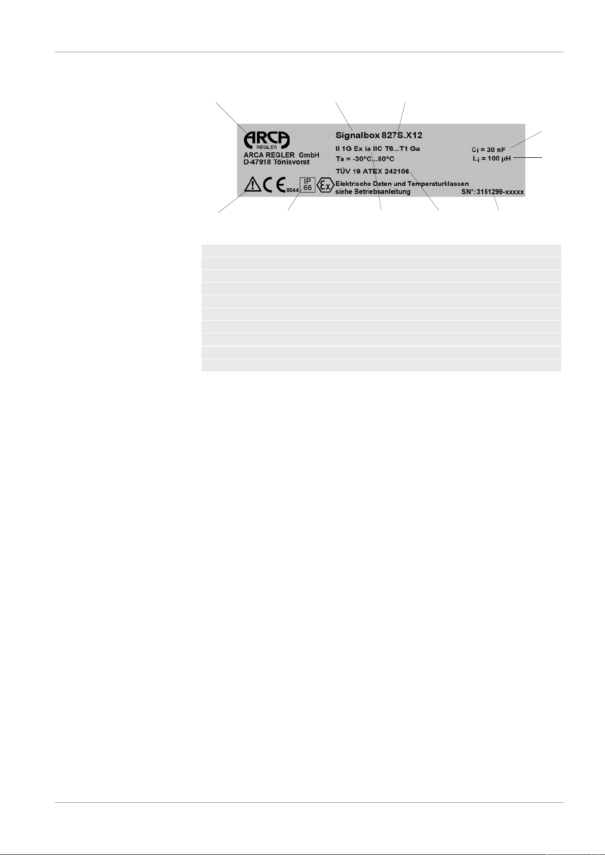
4 Type plate
1 2 3
4 5 7 6
8
9
10
Illustration2: 827S nameplate
1 Manufacturer
2 Device name
3 Type
4 Observe the operating manual
5 Protection class
6 Approval
7 ATEX marking for potentially explosive areas
8 Internal capacitance
9 Internal inductance
10 Fabrication number

5 Type key ARCA Regler GmbH
14 / 42 Series 827S.E/X09.2019 / 1.0
5 Type key
827S. X 2 1
[1] [2] [3] [4]
1. Series
827S.
2. Explosion protection 1)
E not explosion proof
X explosion protected "ia" 1)
3. Number of slot-type initiators
1 1 slot-type initiator
2 2 slot-type initiators
3 3 slot-type initiators 2)
4. Types of slot-type initiators
1 SC 3.5…NO…-BU
2 SJ 3.5-SN
3 SB 3.5-E2 2)
1) ATEX approval, other approvals on enquiry
2) only in explosion protection class "E": not explosion proof
Example of type designation 827S.X21
Signal box 827S – explosion-proof "ia" – 2 slot-type initiators – initiators
type SC 3.5…NO…-BU

ARCA Regler GmbH 6 Description
Series 827S.E/X 15 / 4209.2019 / 1.0
6 Description
6.1 Function
▪ The signal box 827S is used for the feedback of up to 3 freely ad-
justable valve positions (positions of the actuator) to the control sys-
tem. The stroke or rotary movement of the actuator is transmitted to
a shaft by the stroke or rotary angle sensor. This rotary movement is
transmitted directly to an immersion disc. The movement of the im-
mersion disc into or out of the respective slot-type initiator generates
the corresponding electrical signal.
▪ The slot-type initiators can be arranged in arbitrary positions around
this immersion disc and adjusted so that almost any desired switch-
ing position is representable for the slot-type initiator.
6.2 Construction
This section describes the mechanical and electrical construction, the
device components and the principles of the operation of the signal box.
The signal box is used to signal the positions (usually the end positions)
of:
▪ linear actuators or
▪ rotary actuators VDI/VDE 3845
Linear actuators may be mounted in a number of ways.
▪ NAMUR or IEC 60534
▪ integrated mounting (ARCA, SAMSON)
The signal box can be mounted and operated on all normal actuators.
The device is available for single-acting and double-acting actuators as
well as for potentially explosive and non-potentially explosive applica-
tions.

6 Description ARCA Regler GmbH
16 / 42 Series 827S.E/X09.2019 / 1.0
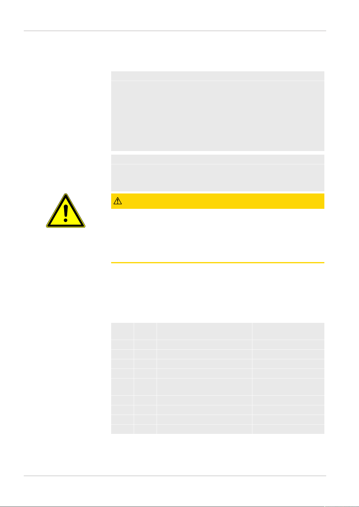
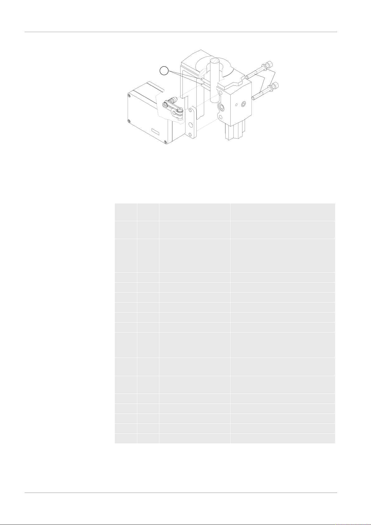
6.3 Device Components
Illustration3: Construction
10 Cable gland
20 Terminal set
30 Proximity switch
40 Screw
50 Washer
60 Screw
70 Washer
80 Switching disc

ARCA Regler GmbH 6 Description
Series 827S.E/X 17 / 4209.2019 / 1.0
90 Circlip
100 Washer
110 Spring washer
120 Spacer sleeve
130 Base plate
6.3.1 Electrical Connections
The signal box's connecting terminals are located on the left-hand side.
7 Assembly ARCA Regler GmbH
18 / 42 Series 827S.E/X09.2019 / 1.0
7 Assembly
7.1 Safety instructions for assembly
CAUTION
Improper installation
Improper installation can result in damage to the device, its destruction
or the impairment of its function.
Ascertain that the device shows no visible signs of damage each time
before installing it.
Ascertain that the process connections are clean and that suitable seals
and cable glands are used.
Install the device using suitable tools.
ATTENTION
The device protection class becoming null and void
Damage to the device due to open or improperly closed housing. The
protection class specified on the nameplate is no longer guaranteed.
CAUTION
Humid environment
If the environment is humid, mount the signal box in such a way that
there is no chance of the shaft freezing at low ambient temperatures.
Make sure that water does not enter an open housing or screw connec-
tion. If the signal box cannot be immediately and permanently mounted
and connected on site, it is possible for water to enter.
7.2 Mounting a linear actuator
7.2.1 Mounting with mounting kit for "Integrated Fitting Linear Actuator"
Included with the "integrated fitting linear actuator" are (see figures be-
low for serial numbers):
Serial
no.
No. of
items
Name Note
1 1 Driver pin cpl. with roller mounted on lever (2)
2 1 Lever
3 1 Washer B6.4 - DIN 125 - A2
4 1 Spring lock washer A6 – DIN 127- A2
5 1 Cylinder screw M6 x 25 - DIN 7984 -
A2
6 1 Hex nut M6 - DIN 6923 – A2
7 1 Square nut M6 - DIN 557 - A4
8 2 Cylinder screw M8 x 65 - DIN 912 - A2
9 2 Spring lock washer A8 - DIN 127 - A2
Mounting procedure (see
figures below) 1. Fig. 5: Adjust the pin (1) on the previously assembled lever (2) to the
value of the stroke range given on the actuator or, if this is not avail-
able as a scale value, to the next larger scale value. In case of un-
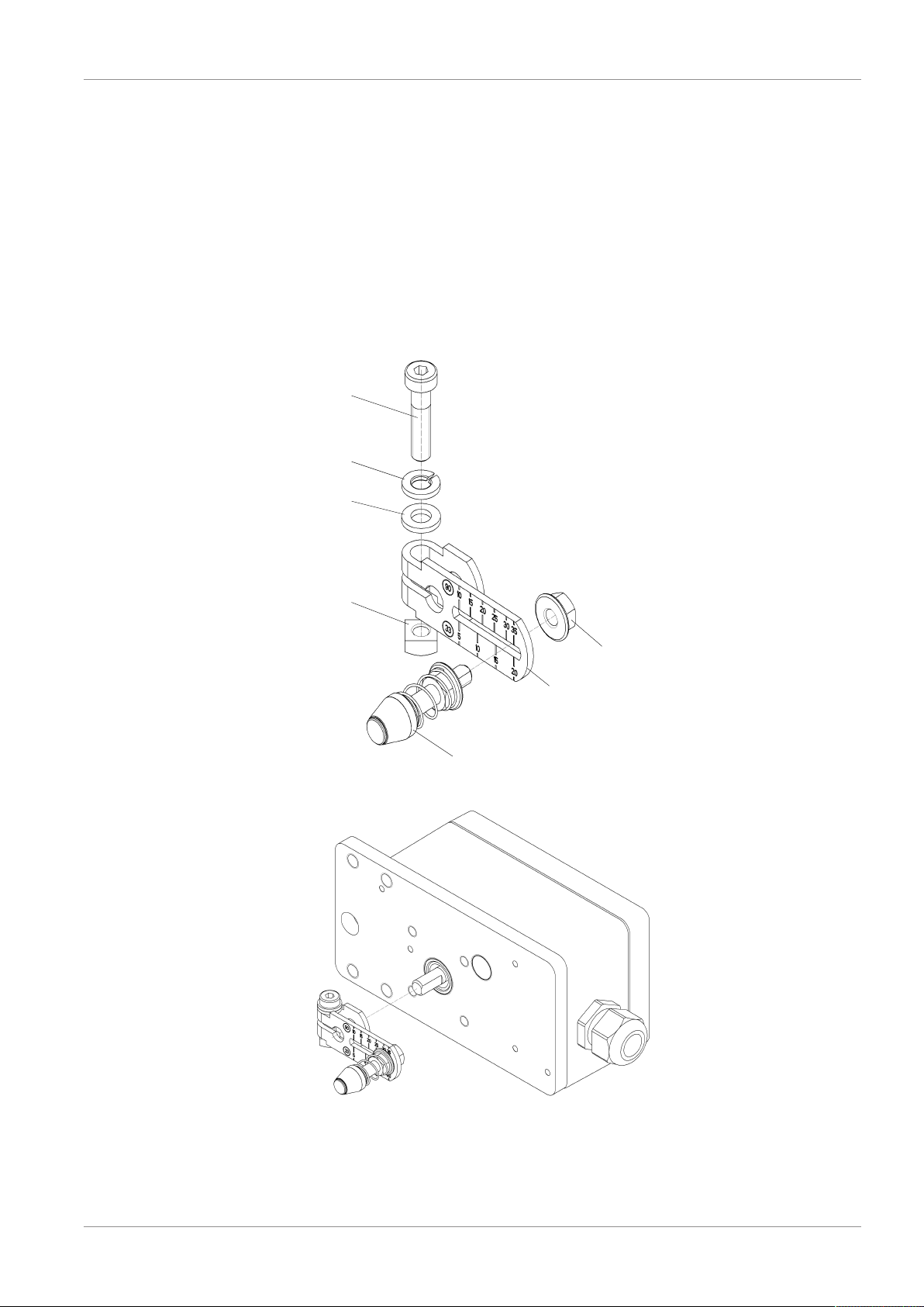
ARCA Regler GmbH 7 Assembly
Series 827S.E/X 19 / 4209.2019 / 1.0
certainty with regard to the actual working stroke (pneumatic actuat-
ors often have a setting distance reserve), the next larger scale value
should be selected. The centre of the pin should rest on the scale
line on the lever (2).
2. Fig. 6: Push the lever (2) to the stop on the signal box shaft and fix it
with cylinder screw (5).
3. Hold the signal box against the actuator in such a way that the roller
passes between the pins (16).
4. Align the signal box horizontally on the yoke and assemble it with the
screws (8) and spring lock washers (9).
Assembly procedure plan -
integrated fitting
5
4
3
7
1
6
2
Illustration4: Lever mounted
Illustration5: Mounting the lever on the signal box
7 Assembly ARCA Regler GmbH
20 / 42 Series 827S.E/X09.2019 / 1.0
16 9
8
Illustration6: Mounting the signal box on the actuator
7.2.2 Mounting with mounting kit "Linear actuator IEC 60534"
Included with the mounting kit "Linear actuator IEC 60534", stroke 3 to
35 mm, are (see figures below for serial numbers):
Serial
no.
No. of
items
Name Note
1 1 Driver pin cpl. with
roller
mounted on lever (2)
2 1 NAMUR lever For stroke range 3 mm to 35 mm,
or (order separately for stroke
range > 35 mm to 130 mm, see
Fig. 10)
3 2 Washer B 6.4 - DIN 125 - A2
4 3 Spring lock washer A6 - DIN 127 - A2
5 3 Cylinder screw M6 x 25 - DIN 7984 - A2
6 1 Hex nut M6 - DIN 6923 - A2
7 1 Square nut M6 - DIN 557 - A4
9 6 Spring lock washer A8 - DIN 127 - A2
17 1 NAMUR mounting
bracket IEC 534
Standardised connecting location
for mounting bracket with rib,
column or flat surface
18 1 Sensing hoop Guides the roller with the driver
pin and turns the lever arm
19 2 Clamping piece Assembly of the sensing hoop to
the actuator's stem
20 2 U-bolts Only for actuators with columns
21 2 Hex screw M8 x 16 - DIN 933–A2
22 6 Washer B 8.4 - DIN 125 - A2
23 4 Hex screw M8 x 20 - DIN 933–A2
24 4 Hex nut M8 - DIN 934 - A4
Mounting procedure (see
figures below) 1. Fig. 9: Assemble the clamping pieces (19) using the cylinder screws
(5) and spring lock washers (4) to the actuator stem.
This manual suits for next models
14
Table of contents


