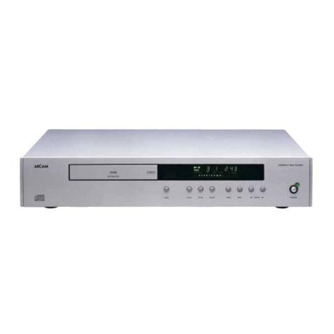
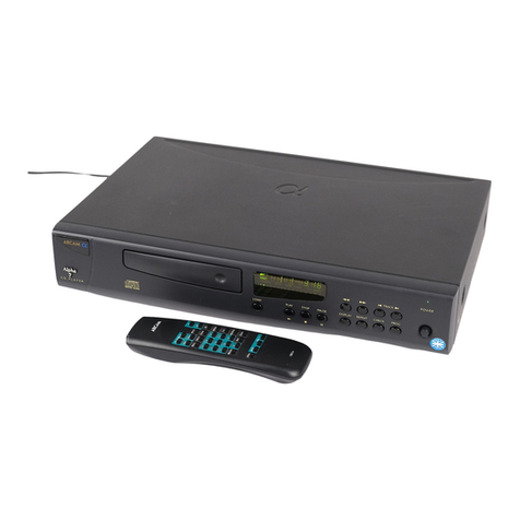
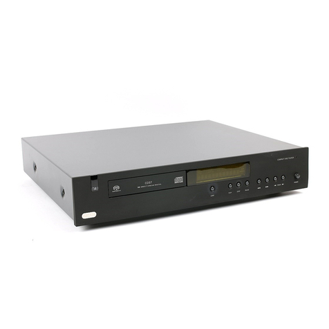
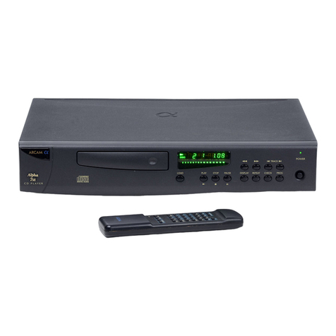
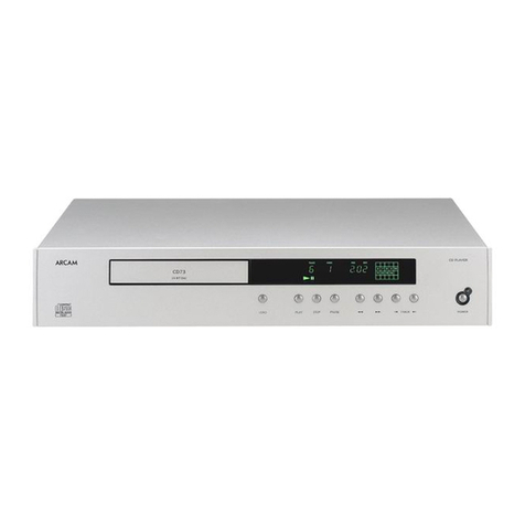
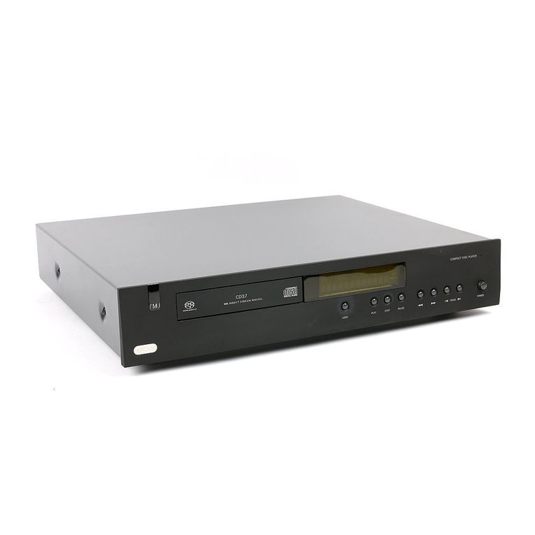
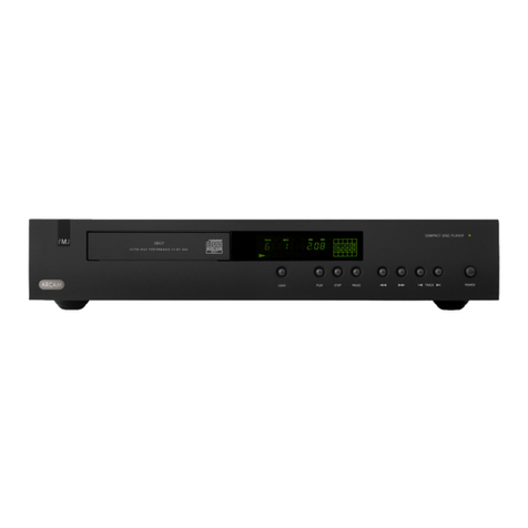
CD72/92 (text) Circuit Description
Summary
The main Motherboard/Display PCBs for the Diva CD players
may be assembled as three different versions:
! DiVA CD62 (text) - With alternate components fitted
and the 92DAC upgrade connections omitted
(L933AY).
! DiVA CD72 (text) - With the standard set of
components fitted (L899AY).
! DiVA CD92 (text) - With analogue components and
connectors omitted, for use as a host motherboard for
the plug-in 92DAC (L934AY).
The CD72T version may be converted for use with an upgrade
plug-in DAC board by changing on-board jumpers.
All systems are based on a Sony kit, comprising CDM14BL-
5BD25 CD transport / loader / laser mechanism, micro-controller
and fluorescent display.
Power Supplies
The CD72/92 transformers :-
! 230/115VAC - part number L866TX
! 100VAC only - part number L851TX
The mains transformer has three secondary windings:
1. 13.7V – 0V – 13.7V to provide ±12V(A) supplies
(IC201 and IC205) for the audio output circuitry via
regulators IC201 and IC205.
2. 9V-0V-32V to produce the digital, motor drive and
fluorescent display grid supplies:
+11V(U) Unregulated supply for relay drive and
+5V(D) supply
+7V (IC200) Mechanism and motor driver
supply
+5V(D) (IC202) General digital logic supply
+5V(A) (IC203) Supply to DAC
-30V (IC204) Display grid voltage.
3. 0-5V to provide an AC supply for the display
filament.
All of these supplies are delivered also to the optional 92DAC
upgrade board via the 92DAC power connector SK203. The
supplies are conventional and are linearly regulated by 3-terminal
voltage regulators.
When the 92DAC upgrade board is used, analogue regulators
IC201 and IC205 can be bypassed by removing JP203 and
JP205, and fitting JP202 and JP204
since regulation is contained
on the 92DAC board itself. Soft-charging resistors R204 and
R205 are be bypassed similarly.
Relay Mute Control
This circuit drives a relay to un-mute the analogue output ~5
seconds after the unit is powered on, and quickly mutes the
output when the unit is switched off. The circuit works
effectively as an “AND” gate.
If AC is present on the transformer secondary winding and the 5-
second timer composed of R222 and C221 has reached the
threshold voltage (Vbe of TR200 + Vbe of TR201 - Vce of
TR202, or ~1.0V), the relay coil is connected to +11V
(referenced to 0V_3 as required by the 9DAC’s internal circuitry)
via TR204.
When AC is removed, C231 discharges quickly through R225,
the base voltage of TR204 rises and the relay coil voltage is
removed, muting the output.
TR203 resets the ‘timer’ by discharging C221 quickly at turn-off.
Remote Control/PIC Micro
Remote controldata is received from the IREye on the display PCB
and buffered by TR300 and TR301. The Programmable Interrupt
Controller converts the RC-5 format data into the NEC format
required by the Sony micro. The PIC also controls the configuration
of the digital filter/DAC on the DAC board.
Motor Driver
The status of the drawer is indicated to the micro by two micro
switches ‘INSW’ and ‘OUTSW’ on SK205. The micro controls
the drawer motor via driver IC303.
Clock Buffering
The clock and data signals LRCK, ADATA and BCLK from the
mechanism connector SK300 are double buffered by IC300
before being delivered to the DAC.
Power-On/Reset
The power-on reset signal XRST (or RESET) is generated by
R409, C410 and IC404. When the power is turned on, C410 is
initially uncharged and pin 11 of IC404 is at high voltage, and
thus the output is low. After a short time, C410 is charged via
R409; IC404 pin 11 is then low, and the output switches high
(RESET is de-asserted).
DAC & System Clock
The DAC is a Burr Brown PCM1716E, the DAC is configured
for hardware control.
Digital audio is input on pins 1, 2 & 3 in standard Red Book
Audio format, i.e. Word Clock, Bit Clock and Data.
The system clock is based around 16.9344 MHZ crystal X400
and transistor TR402. This produces a stable clock with low
jitter. IC404A & B buffer the clock as linear buffers. IC404C &
D buffer the individual mech & DAC clock lines.
The CD92 system clock is generated on the 92DAC board.
The clock and data signals LRCK, ADATA and BCLK from the
mechanism connector SK300 are double buffered by IC300 before
being delivered to the DAC. The system clock is delivered to the
mech via two-position jumper PL300. The clock source is selected
to be either from the main board (CD62/72) or from the 92DAC
board (CD92) by the position of JP300.
When the 92DAC is fitted as an upgrade to a CD72,
removing JP400 disables the main board clock

