Archer VR2K Owner's manual

Archer Instruments, LLC www.archerinstruments.com
Model VR2K
High Volume Vacuum Regulator
Installation, Operation & Maintenance
General: The Archer Instruments Model VR2K vacuum regulator is designed for use in
vacuum gas feed systems. The VR2K can be provided with or without an integral pressure
gage.
Safety: When working with chlorine, always use caution and follow applicable safety
procedures. General safety considerations:
* Store chlorine separately from ammonia.
* When using chlorine, avoid locations that expose the chlorine containers and feed
equipment to direct sunlight.
* Do not apply heater or heat source directly to chlorine containers.
* Ton Containers: Use appropriate handling equipment when moving ton containers. When
readying ton container for use, ensure valves are aligned vertically. The top valve accesses
gaseous chlorine and the bottom valve accesses liquid chlorine. The bottom valve should
never be touched unless your system employs a chlorine heat exchanger (evaporator)
designed expressly for use with liquid chlorine.

Archer Instruments, LLC www.archerinstruments.com
Installing the Model VR2K:
*IMPORTANT SAFETY NOTES:
- The VR2K inlet assembly is connected to the back of the vacuum regulator by means of a
lead gasket seal (lead gasket part# LGA-3) and four (4) socket head cap screws. Prior to
use and during any periods of significant change in ambient temperature, these screws
should be checked to make sure they are tight. 20 lbs of torque is recommended. The LGA-3
lead gasket should be replaced once each year, but only after the pressure manifold has
been properly evacuated.
- The VR2K is equipped with a drip leg and heater, which is designed to trap any solids
entering the unit and also to trap any chlorine that might have re-liquefied inside the
pressure manifold. The drip leg heater should be hot prior to operating the system.
- Pressure manifolds must include an adequate number of heated drip legs to trap the liquid
chlorine discharged from each ton container during initial use. It is also recommended that
the pressure manifold be constructed so that the line entering the VR2K is higher than the
rest of the pressure manifold, so as to prevent the possibility of excessive liquid chlorine
entering the VR2K vacuum regulator body.
1) Wall-mounting: After selecting the best location, mount the VR2K to the wall using the
wall-mounting hardware provided, connecting onto the VR2K as shown in Figure 1. The
VR2K must be installed vertically (as shown) with the drip leg down.
2) Gas inlet: The gas inlet connection on the VR2K is a 2-bolt 3/4” NPT union, which is
sealed with one lead gasket. Using proper PTFE thread treatment, connect the gas manifold
to the Archer union and using one LGA-3 lead gasket (included), bolt the union together. 20
ft/lbs of torque is recommended. Do not overtighten.
3) Vacuum: The VR2K vacuum connection is a 1” sch. 80 PVC union. Archer recommends all
vacuum lines be sch. 80 PVC 1” pipe.
4) Vent: All Archer vacuum regulators are equipped with a vent tubing connection for
directing and venting chlorine gas to a safe location. Tubing (1/2” O.D.) is also provided.
5) Heater: Prior to startup of the system or prior to placing any new ton container on
suction, the drip leg heater(s) must be powered for at least 15 minutes. This will ensure
any trapped chlorine liquid is evaporated before reaching the VR2K inlet valve. The heater
must always be powered during operation.
6) Refer to Figure 2 for proper gas feed system configurations.

Archer Instruments, LLC www.archerinstruments.com
Figure 1
NOTE: Vent tubing should always be connected and run to a safe location (outside of any
building). A vent screen (provided with every Archer Instruments vacuum regulator) should be
fitted over the end of vent tubing to prevent insects from entering.
Figure 2

Archer Instruments, LLC www.archerinstruments.com
Operating the Model VR2K:
1) Before placing the VR2K vacuum regulator into operation, it is important to carefully test
each lead gasket seal. A small squeeze bottle (provided with every Archer Instruments
vacuum regulator) should be partially filled with ammonia. Squeezing the bottle allows the
ammonia fumes to be used to test for chlorine leaks. A leak is detected by a visible light
gray / white gas cloud when the two fumes interact. To test for leaks, open each container
valve ¼ turn and then close immediately. This pressurizes the lead gasket seal but ensures
the container of chlorine is isolated during leak testing. Use ammonia fumes around the
cylinder valve and each lead gasket to check for any signs of leaking gas. If a leak is found,
this must be addressed before placing the unit into operation.
2) After confirming no leaks exist, open the chlorine cylinder valve 1 turn. This is fully open
and there is no need to open the valve further. Archer Instruments recommends leaving the
wrench on the valve stem whenever a container valve is open.
3) The VR2K operates using vacuum supplied by the ejector. Once the gas supply has been
prepared for operation and pressurized gas is supplied to the VR2K, gas feed will begin when
the ejector is put into operation.
NOTE: If the gas supply to the VR2K is exhausted, the guide pin will retract into the
front body. This indicates that gas is no longer flowing and that increased internal
vacuum has caused the diaphragm to fully open the inlet valve. When a high internal
vacuum level exists the diaphragm assembly will seal against the inside of the back body
until either the vacuum is relieved or the gas supply is restored.
Maintaining the VR2K:
Recommended Maintenance Frequency: Archer Instruments recommends yearly routine
maintenance of the VR2K vacuum regulator.
-Refer to the following parts diagram when performing maintenance on the VR2K.
NOTE: Prior to removal, the gas manifold must be properly evacuated to be sure all chlorine
has been removed and no pressure remains in the system.
DISASSEMBLY:
1) Remove the four BTA-139 cap screws and pull the drip leg & inlet assembly straight
out of the back of the vacuum regulator. Take care to pull it straight away, so as to
avoid damaging the VRA-644 Filter Holder.
2) Remove the four BTA-125 body screws and two BTA-131 back plate screws, then
carefully separate the VR2K front and back bodies.
3) The diaphragm assembly can then be removed by pulling it straight out of the front
body. Take care to not lose the vent spring, which is located between the diaphragm
assembly and the front body.

Archer Instruments, LLC www.archerinstruments.com
4) It is generally not necessary to remove the VRA-600 guide pin for routine
maintenance. Simply replace the OA-VIT-006 o-ring. However, the guide pin can be
unscrewed by hand or (if necessary) by using a pair of pliers.
5) The diaphragm back plate VRA-56A and diaphragm front plate VRA-269 are threaded
together and can often be unscrewed by hand. If they will not unscrew by hand, it
may be necessary to use a vice and / or channel locks.
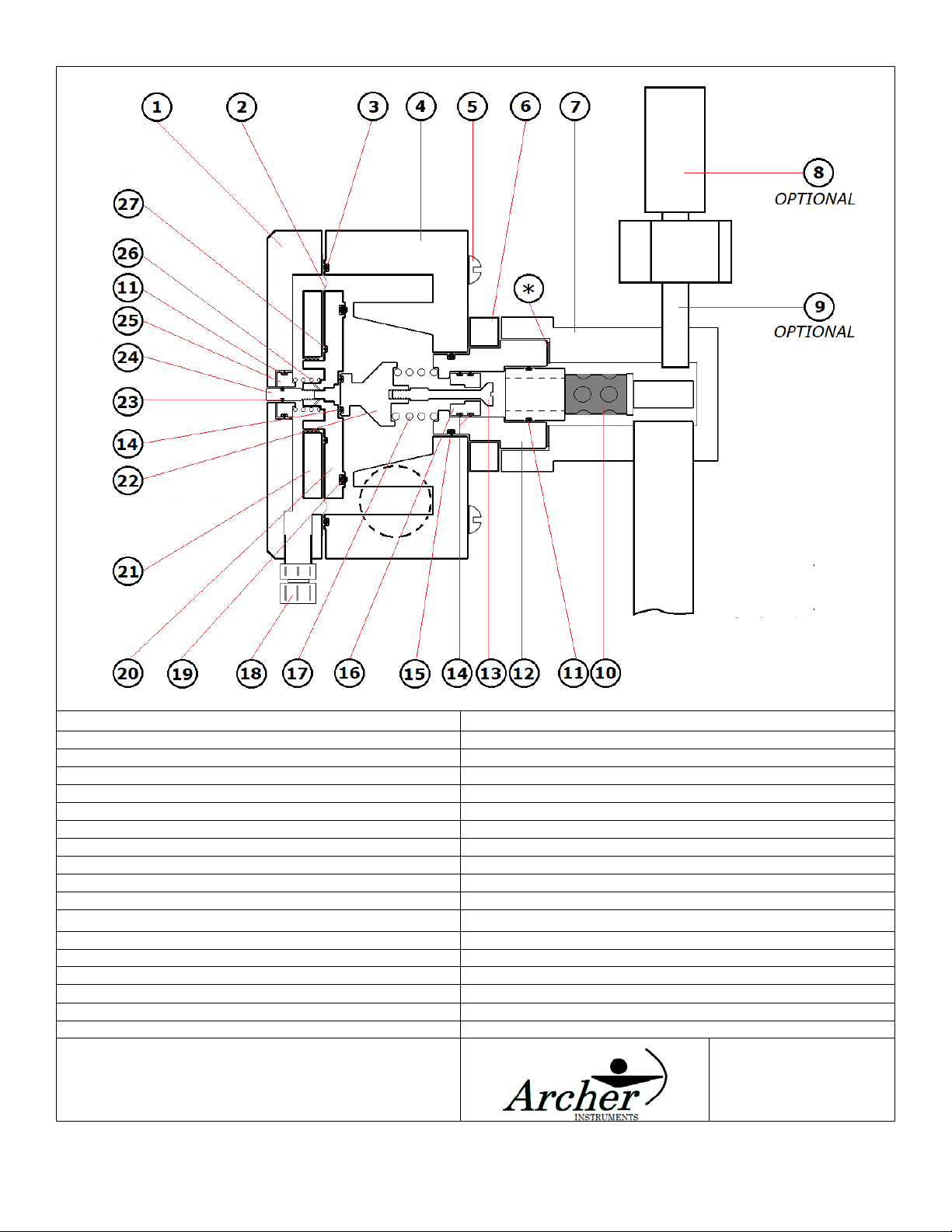
6) To complete disassembly of the back body and inlet valve assembly:
a. Remove the VRA-644 filter holder from the inlet capsule by pulling it straight
out. It is held only by an o-ring fit. It may be necessary to use pliers to twist
and pull the VRA-644.
b. Remove the old LGA-3 lead gasket by carefully prying it away from the VRA-645
inlet capsule.
c. Using a flat head screwdriver, carefully unscrew the inlet valve stem VRA-647
from the spring retainer VRA-649. Remove the stem, spring retainer and SPA-
639 inlet spring.
d. The inlet capsule VRA-645 and back plate VRA-646 can be separated from the
back body VRA-641 using a mallet or similar implement to tap on the inlet
capsule from the inside of the back body.
e. The inlet capsule is press-fit into the back plate. Once they are separated from
the back body, the inlet capsule can be pressed or knocked out of the back
plate.
f. The inlet valve seat VRA-648 is o-ring fit into the inlet capsule and can be
pressed or tapped out of the capsule. The inlet valve seat should always be
replaced during maintenance.
7) The filter holder VRA-644 incorporates a wrapped silver screen through which all gas
entering the unit must pass before reaching the inlet valve. This screen can be
cleaned in place using compressed air, hot water, etc. If necessary, the screen can be
carefully removed and cleaned using a solvent such as acetone. If the screen is
damaged or torn the VRA-644 should be replaced.
8) Whenever routine maintenance is being performed, all parts should be thoroughly
cleaned. It is recommended that the inlet valve seat and all o-rings (with the
exception of the OA-VIT-332) be replaced.
9) When reassembling, new o-rings should be given a thin film of the Fluorolube grease.
SAFETY NOTE:The inlet valve assembly is a critical component of the VR2K. Improper
handling or reassembly can result in dangerous leakage of chlorine gas. Archer
Instruments recommends that only trained personnel or those familiar with
vacuum regulator maintenance service the VR2K.
-Should you have any questions during maintenance of your VR2K vacuum regulator, please
contact your local service provider or Archer Instruments for support.

Archer Instruments, LLC www.archerinstruments.com
Item# Qty. Part # Description
1 1 VRA-642 Front Body
18 1TCA-84 Tube Connector (Vent)
2 1 DIA-640 Double Diaphragm
19 1 OA-VIT-332 O-Ring
3 1 OA-VIT-047 O-Ring
20 1 VRA-56A Diaphragm Back Plate
4 1 VRA-641 Back Body w/ 1” Union
21 1 VRA-269 Diaphragm Front Plate
5 4BTA-125 ¼-20 x 2-3/4” Body Screw
22 1 VRA-649 Spring Retainer
6 1 VRA-646 Back Plate
23 1 OA-VIT-006 O-Ring
7 1 VRA-643 Inlet Manifold
24 1 VRA-600 Guide Pin
8 1 PGL-200 Pressure Gage Assembly
25 1 VRA-104 Pin Guide
9 1 VRA-650 ¼” Monel Nipple
26 1SPA-100 Vent Spring
10 1VRA-644 Filter Holder & Silver Screen
27 1 OA-VIT-029 O-Ring
11 2OA-VIT-014 O-Ring
*1LGA-3 Lead Gasket
12 1 VRA-645 Inlet Capsule
NOT SHOWN:
13 1 VRA-647 Inlet Valve Stem
2 BTA-131 ¼-20 X 3” Back Plate Screw
14 3 OA-VIT-013 O-Ring
4 BTA-139 3/8-16 x 1” Cap Screw
15 1 OA-VIT-214 O-Ring
1 OA-VIT-215 O-Ring - inside 1” PVC Union
16 1 VRA-648 Inlet Valve Seat
1 HTA-111 Drip Leg Heater
17 1 SPA-639 Inlet Spring
1 LGA-3 Lead Gasket -inside pressure union
Notes:
1. Vacuum Connection is 1” PVC Sch. 80 Socket Union
2. Vent Tubing is ½” O.D.
Date: Nov 2019
Drawing #: VR2K
Other Archer Controllers manuals
Popular Controllers manuals by other brands

Canon
Canon imagePASS-P2 Service manual

Alfalaval
Alfalaval ESE02126-EN5 instruction manual

NAU ROBOTICS
NAU ROBOTICS RC40A Operating instruction

Trane
Trane Tracer UC400 Installation, operation and maintenance

Exalux
Exalux CONTROLSKY user manual

Transmitter Solutions
Transmitter Solutions PAL SPIDER WIEGAND 26 user manual