Arcomora DCC Next User manual

Assembly manual DCCNext Version 3.2.1

Place all components on the print as indicated below.
Check that all parts are present. Please contact Arcomora a.s.a.p. if you are missing something.
Partslist resistors/capacitors:
R1: 10k ohm. Brown, black, black, red, brown
R2, R3: 2k2 ohm ½ Watt. red, red, black, brown, brown
R6: 2k ohm. Red, black, black, brown, brown
R4, R7, R8: 1k ohm. Brown, black, black, brown, brown
C4: 470 uF C8: 47 uF C1, C9, C5, C7: 100 nF (‘104’)
C2, C3: 22pF (‘22’) C6: 220 pF (‘221’ or no print)
Insulation plate

1. Place all resistors R1 to R8. Note the colour codes (there is no R5)
2. Place diodes D2, D3 and D5. Note the orientation.
3. Place both IC feet. Note the orientation. The cut-outs to the edge of the print.
Make sure that ALL pins protrude through the print. If placed incorrectly, that is no problem; pay
extra attention to the placement of the ICs.
4. Install the DB107 (D1) diode bridge and the L7805. Secure the L7805 with a nut and bolt.
Note the orientation of both components.
5. Install all capacitors except C4 (470 uF) and C8 (47 uF). C6 and C7 have an imprint ‘22’.
C6 has an imprint ‘221’or no imprint. The others (100 nF) have an imprint of ‘104’.
6. Place the oscillator and the reset switch. Place the insulation plate under the oscillator!
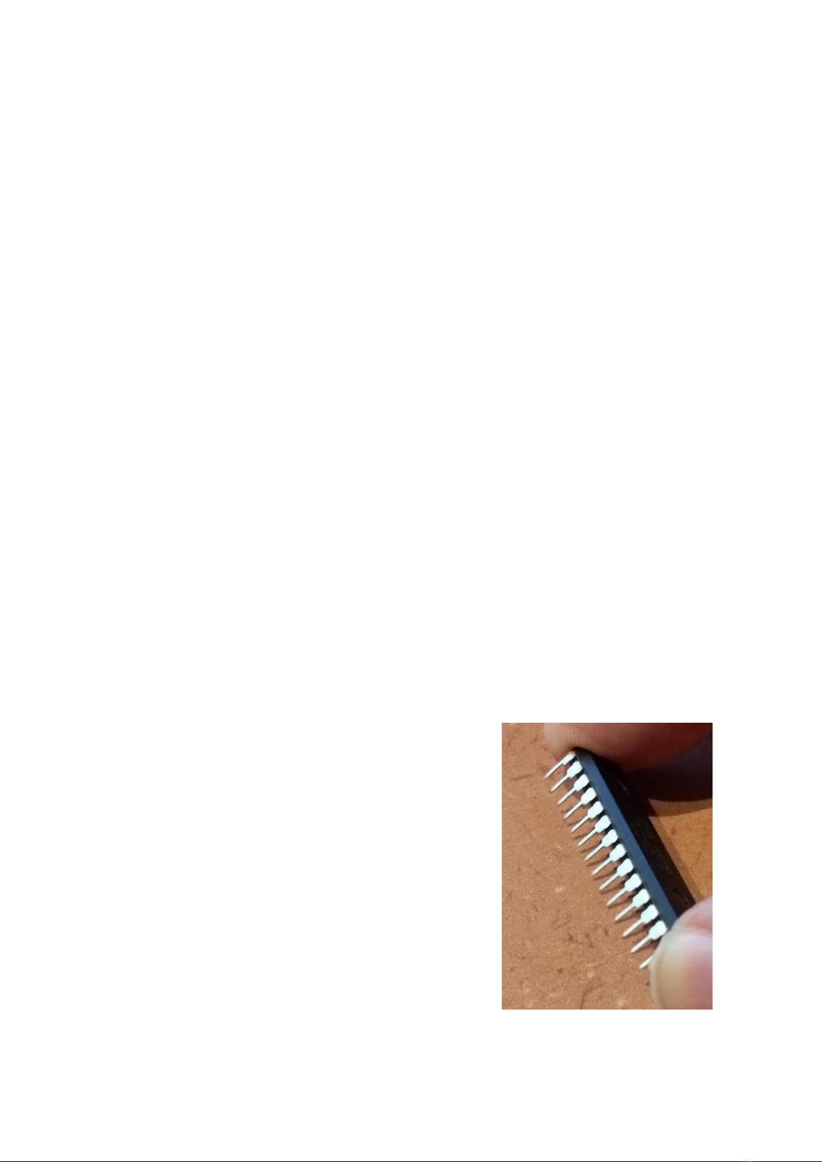
7. Cut 2 pieces of 3 Dupont pins and place them in the holes at the LM7805.
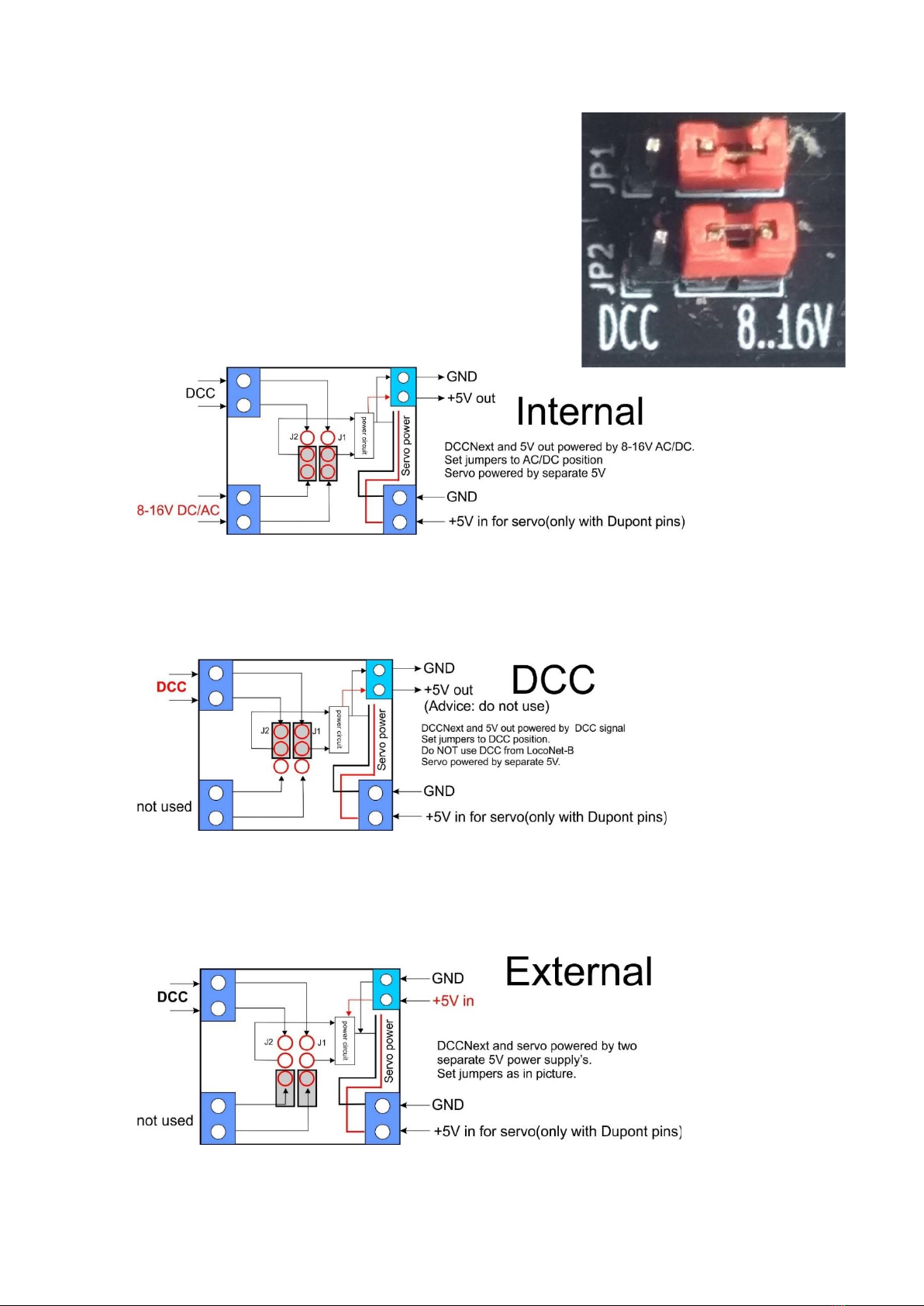
After soldering, place both jumpers over the pins at 8-16V or a DCC. See below for an explanation of
the power options
8. Place the 4 LEDs with the correct color. Note the orientation. The long leg is the plus (+).
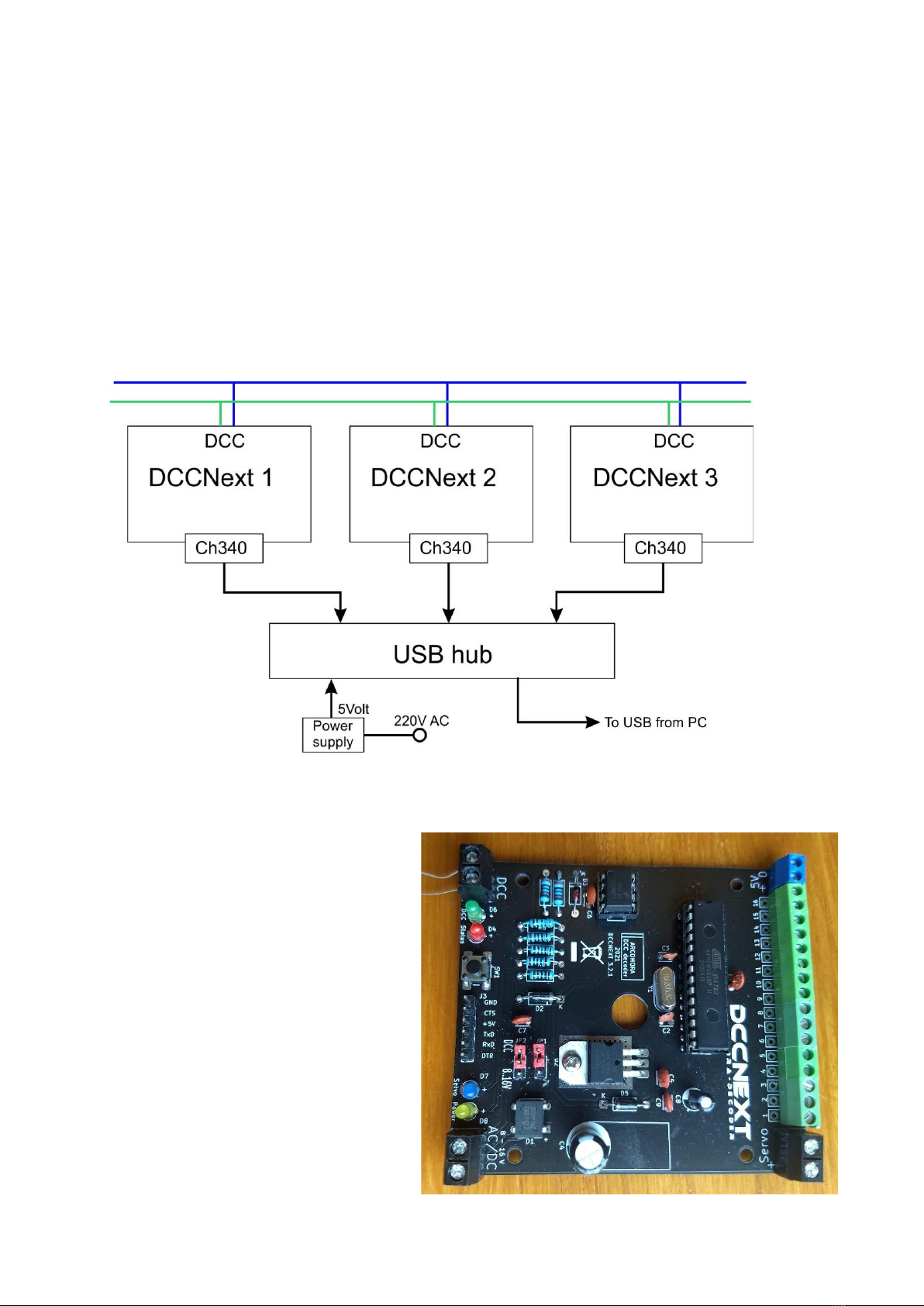
9. Cut a piece of 6 Dupont pins and place this at Serial.
If desired, you can also solder the hooked Dupont pin as supplied with the USB interface. (See also
below for the USB connection options).
10. Only if you want to connect servos directly:
Cut pieces of 3 pins and solder them on the print. Do this preferably from port 1. Naturally you must
also configure the servos for these ports at Mardec. By using both 2-pole and 3-pole connections you
can make any number of 2 to 12 servos. Only one servo is not possible.
11. Slide the required number of terminal blocks together and solder them onto the print. If you have
not used servo pins, you must assemble them all. Place the terminals on the print first. Then turn it
over and push the print against the desk. Because of this the terminals are stuck and you can easily
solder.
NOTE: Use the small blue terminal for the 5Volt connection.
12. Install the 3 blue big screw terminals. Do this in the same
way as the green screw terminals.
13. Install capacitor C6. Note the orientation; the long leg is the
plus.
14. Install capacitor C4. Note the orientation. This can be done
in upright or lying position. Make sure that the capacitor lies
tight against the PCB when placed in the upright position and
the box is used.
15. Install IC 6n137 and the ATMEGA328P processor. Usually
the legs are too far apart so that they do not fit well in the foot.
To bend them, place one side against the work surface and
push all legs at the same time a little to the right. Do this for
both sides.

If you also use the box, stick the stickers on the lid.
Note: on the connector side, the sticker must
be folded over the edge.
Tip: Stick a piece of transparent plastic over
both stickers for protection.
(not included!)
The assembly is now complete and we can start testing the DCCNext. For this purpose there is a
special test program on the processor.
1. Connect the USB interface to the PC.
The yellow power LED should light up and the red status LED should blink.
2. Now connect the DCC signal to the DCC terminals. The green LED should now also light up.
3. Now send any DCC address, greater than 1, to the DCCNext.
The red LED will now blink rapidly. This proves that the DCC signal is 'seen' by the DCCNext.
4. Send DCC address 1. The red LED will now blink more slowly again.
5. Repeat points 3 and 4 to test multiple addresses.
The 16 ports can also be tested.
6. Connect a led with in series a resistor of
about 1k between the gnd of the servo power
and a port.
This LED will now blink at the same rate as the
status LED.
Now connect the led to all 16 ports. This will test
the individual ports.
For Dupont pins use the pin closest to the edge.
Tip:
Wait to solder R7 and D7 (servo led).
Use these first for this test.
7. Now put the jumpers in the DCC position and remove the USB cable.
Everything keeps working. There should be no difference.
8. Reconnect the USB cable and remove the jumpers.
Everything continues to work. There should be no difference.
9. Connect a voltage to the screw terminals and put the jumpers in the 8-16V position.
Remove the USB cable. Everything continues to work. There should be no difference.
10.Only if you use Dupont pins:
Solder R7 and D7 if you have not done so already for the test at point 6.
Connect a voltage of 5V to the servo terminal.
The blue LED should now light up.

USB-Serial CH340 Interface
The USB interface can be mounted in 4 different ways:
1) Standard method:
2) Fixed soldered:
3) Hooked method:
This method saves space. The danger is that the interface is set up incorrectly; so with the
USB connector on the other side.
However, only one set of female connector with angled connector is supplied.
So if you want to use the interface on multiple prints, an extra female connector is needed.
4) Hooked soldered:
Make sure that the switch is in the 5V position!

Schema DCCNext (V3.2.1):

Power Options:
There are 4 options for supplying power to the DCCNext.
1) Internal. The DCCNext is powered by the internal power
circuit on the board.
Connect a power supply to the big blue screw terminal.
For servos connected to the Dupont pins a separate 5V must
also be connected.
On the 5V output a voltage is available for LEDs (max 500mA).
Never connect a relay or servo permanently to this output.
Only do that for testing purposes.
Put both jumpers on the position 8-16V.
2) DCC. The DCCNext is powered by the DCC signal connected to the DCC terminal.
The LocoNet Railsync signal can NOT be used.
For servos connected to the Dupont pins a separate 5V must be connected.
Put both jumpers in the DCC position.
3) External. The DCCNext is powered from the blue 5 Volt terminals.
This can be a low power supply.
For servos connected to the Dupont pins, a separate 5V must also be connected
Do not connect a power supply to the normal input.
Set the jumper as indicated in the picture.

4) Via the USB interface.
Connect the USB interface to the PC.
The DCCNext receives a 5V power supply from this connection.
This option is best used in combination with a USB hub with its own power supply.
This hub can be used for connecting several DCCNexts and each DCCNext gets its own COM-port
when the hub is always connected to the same USB port of the PC.
For each DCCNext a Putty session can be started and the activity can be monitored.
Do not connect anything to the AC/DC input and the 5V output.
If you connect servos directly to the Dupont pins, do connect a separate 5V power supply to the
servo screw terminal.
Set the jumpers as indicated in the figure at External.
With this USB option, you do not need to mount the power supply circuit.
The following components are then
not needed:D1 = DB107
C4 = 470 uF
C5 = 100 nF
IC1 = LM7805
C9 = 100 nF
C8 = 47 uF
D5 = 1N5817
Pins for the jumpers
AC/DC screw terminal
If you don’t know what to do then
choose option 1 (Internal)
Table of contents
Other Arcomora Media Converter manuals