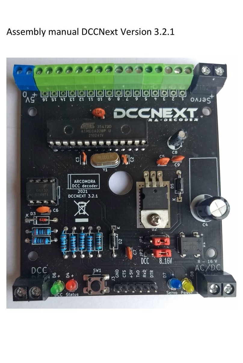
1. Place all resistors R1 to R8. Note the color codes
2. Place diode D1. Note the orientation.
3. Place both IC feet. Note the orientation. The cut-outs to the edge of the print.
Make sure that ALL pins protrude through the print. If placed incorrectly, that is no problem; pay
extra attention to the placement of the ICs.
4. Install the DB107 diode bridge and the L7805. Secure the L7805 with a nut and bolt.
Note the orientation of both components.
5. Install all capacitors except C1 (1000uF) and C3 (10uF). C6 and C7 have an imprint 22. C9 has an
imprint 221. The others (100 nF) have an imprint of 104.
6. Place the oscillator and the reset switch. Keep the oscillator 5 mm. above the pcb.
7. Cut 2 pieces of 3 Dupont pins and place them in the holes at C1. Place the jumper over the middle
pins (servo); then they remain well positioned.
After soldering, place the jumper over the pins at Internal. See below for an explanation of the power
options
8. Place the 4 LEDs with the correct color. Note the orientation. The long leg is the plus (+).
9. Cut a piece of 6 Dupont pins and place this at Serial.
If desired, you can also solder the hooked Dupont pin as supplied with the USB interface. (See also
below for the USB connection options).
10. Only if you want to be able to connect servos directly:
Cut pieces of 3 pins and solder them on the print. Do this preferably from port 1. Naturally you must
also configure the servos for these ports at Mardec. By using both 2-pole and 3-pole connections you
can make any number of 2 to 12 servos. Only one servo is not possible.
11. Slide the required number of terminal blocks together and solder them onto the print. If you have
not used servo pins, you must assemble them all. Place the terminals on the print first. Then turn it
over and push the print against the worktop. Because of this the terminals are stuck and you can
easily solder.
NOTE: Instead of 6 green 2-pole connections, one blue and 5 green connections can be added. Use
the blue one for the 5Volt connection.
12. Install the 3 blue big screw terminals. Do this in the same
way as the green screw terminals.
13. Install capacitor C3. Note the orientation; the long leg is the
plus.
14. Install capacitor C1. Note the orientation. First lay the
capacitor flat against the PCB before soldering.
15. Install IC 6n137 and the ATMEGA328P processor. Usually
the legs are too far apart so that they do not fit well in the foot.
To bend them, place one side against the work surface and
push all legs at the same time a little to the right. Do this for
both sides.
Pay attention to the orientation when installing!
16. Now connect the USB interface to the PC.
If all is well, the red status LED will now flash quickly.


