SightLine 4000-OEM User guide

© SightLine Applications, Inc.
EAN-Startup Guide 4000-OEM
2022-04-06
Exports: Export Summary Sheet
EULA: End User License Agreement
Web: sightlineapplications.com
1Overview.............................................................1
1.1 Additional Support Documentation ...................1
1.2 SightLine Software Requirements ......................1
2Safe Device Handling..........................................1
34000-EVAL Kit .....................................................1
4Hardware Bench Setup.......................................2
4.1 Additional SightLine Adapter Boards..................3
5Network Configuration.......................................3
5.1 Static IP Configuration Through Ethernet ..........4
6Serial Communications.......................................4
6.1 Direct Serial Connection (optional): ...................4
6.2 USB Device Driver...............................................5
7Panel Plus ...........................................................5
7.1 Camera Acquisition ............................................7
7.2 Stream Network Video to This PC ......................8
8Summary ............................................................8
8.1 Demo Mode........................................................9
9Modifying Encoder Parameters..........................9
10 Troubleshooting ...............................................10
10.1 Send Diagnostic Files to SightLine Support ......11
10.2 Nonfunctional SLA-4000-MIPI-IN Board (4000-
MIPI-IN Kit).......................................................12
10.3 Questions and Additional Support ...................12
CAUTION: Alerts to a potential hazard that may result in personal injury, or an unsafe practice that causes damage to the equipment
if not avoided.
IMPORTANT: Identifies crucial information that is important to setup and configuration procedures.
Used to emphasize points or reminds the user of something. Supplementary information that aids in the use or understanding of the
equipment or subject that is not critical to system use.

EAN- Startup Guide 4000-OEM
© SightLine Applications, Inc. 1
1Overview
This Startup Guide provides the steps for connecting, configuring, and testing the 4000-OEM video
processing board. The 4000-OEM board provides the standard connections for power and
communication as well as general purpose IO and camera connections.
For 4000-OEM software debugging capabilities see the 4000-DEBUG board in the ICD-4000-OEM. The
DEBUG board gives the developer access to a debug serial port at RS-232 level, a USB
programming/debugging port, and a switch/button combination for board recovery.
1.1 Additional Support Documentation
Additional Engineering Application Notes (EANs) can be found on the Documentation page of the
SightLine Applications website.
The Panel Plus User Guide provides a complete overview of settings and dialog windows. It can be
accessed from the Help menu of the Panel Plus application.
The Interface Command and Control (IDD)describes the native communications protocol used by the
SightLine Applications product line. The IDD is also available as a PDF download on the Software
Downloads page.
1.2 SightLine Software Requirements
IMPORTANT: The Panel Plus software version should match the firmware version running on the
board. Firmware and Panel Plus software versions are available on the Software Download page.
2Safe Device Handling
CAUTION: To prevent damage to hardware boards, disconnect all input power to OEMs and adapter boards before
connecting or disconnecting cables including all FFC, FPC, KEL, HDMI, MIPI, and round wire (Molex) cables.
CAUTION: To prevent damage to hardware boards, use a conductive wrist strap attached to a good earth ground.
Before picking up an ESD sensitive electronic component, discharge built up static by touching a grounded bare
metal surface or approved antistatic mat.
34000-EVAL Kit
Provides a complete laboratory bench/development interface with standard connectors. For additional
options and interface boards, please contact Sales. To review all the interface board options, see the
4000-OEM Accessories page on the SightLine Applications website.
The 4000-OEM will also support a number of USB Webcams and USB 3.0 Vision cameras.
Table 1: 4000-EVAL Kit
Part Number
Qty
Description
Part Number
Qty
Description
4000-SOM
1
Video processing board
SLA-PWR-B12V-36W
1
12V Power supply w/ 2p connector (36W)
plus AC power cord
4000-OEM
1
REV A, PCBA
SLA-CAB-0504
1
5P PicoBlade to 3P Molex, and pigtail
SLA-PAD-020-01
1
Thermal pad pink 0.020-inch x
1.63-inch x 0.010 inch with 0.5 x
0.5 cutout
SLA-CAB-0804
1
8P PicoBlade to 3P (2) Molex, and pigtail

EAN- Startup Guide 4000-OEM
© SightLine Applications, Inc. 2
(4000-EVAL Kit continued)
SLA-PAD-010-01
1
Thermal pad 1.4-inch x 1.6-inch x
0.010 inch
SLA-CAB-0305
1
TTL (3.3V) to USB serial cable w/ 3p Molex
4000-OEM-MP
1
4000-OEM mounting base
SLA-CAB-0402
1
4p Molex to pigtail
4000-BRACKET
1
4000-OEM heat sink bracket
SLA-CAB-TC2USB
1
USB3.0 Type-C to Type-A adapter
SLA-3000-HDSDI-IN
1
HDSDI-IN Adapter board
SLA-CAB-HD10
1
HDMI output cable
SLA-DIST
1
PWR/ENET distribution board
SL00852
1
HDMI out adapter, female
SLA-KIT-4000-DEBUG
1
4000-DEBUG PCBA, kit
SLA-MSD-ADPT
1
SD adapter
SLA-CAB-0405
1
4-in Molex-to-Molex PicoBlade, 3.0
inches, PWR (BLK/RED)
SLA-CAB-MCX2BNC
1
Cable, MCX (RA) to BNC(M) for HDSDI-IN
SLA-CAB-0404
1
4-in Molex-to-Molex PicoBlade, 3.0
inches, GEN (WHT)
SLA-CAM-HDSDI
1
HD-SDI 1080p camera
SLA-MSD-32GB
1
32GB uSD card (installed)
SLA-PWR-A12V
1
12V Power Supply for camera
SLA-CAB-1505
1
4p PicoBlade to pigtail
Mounting hardware
-
Spacers and mounting screws
4Hardware Bench Setup
IMPORTANT: To prevent damage to hardware boards, disconnect the power before connecting or
disconnecting all cable connections.
Included boards:
•SLA-DIST: Provides power switch and standard bench interface connections for power and ethernet
connections.
•SLA-3000-HDSDI-IN: Provides camera interface to HDSDI cameras.
Cable connections:
•SLA-CAB-MCX2BNC: Connects to J1 (MCX jack) on the 3000-HDSDI-IN board and to the green BNC
connector of the 1080p camera.
The yellow BNC connector is for analog use only.
•SLA-CAB-0404: Connects to J3 on the SLA-DIST board and J4 on 4000-OEM. Provides Ethernet to
the 4000-OEM.
•SLA-CAB-0405: Connects to J50 on the 4000-OEM board and J2 on the SLA-DIST board. Provides
power to the 4000-OEM.
•SLA-PWR-A12V (110-250VAC input / 12VDC output): Connects to the red power connector on the
HD-SDI 1080p camera.
•SLA-PWR-B12V-36W (110-250VAC input / 12VDC output): Connects to J4 on the SLA-DIST board.
Power and network connectivity LEDs:
•A green light (D1) on the 4000-OEM indicates that all boards are powered on. An amber light (D5)
verifies network connection.
•To prevent voltage spikes to the board, plug in the power adapter to an AC power source first and
then connect to the board.
EAN- Startup Guide 4000-OEM
© SightLine Applications, Inc. 3
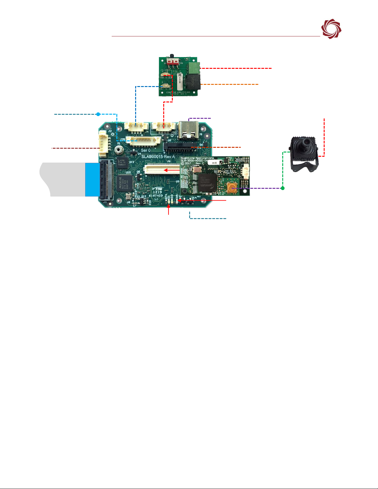
Figure 1: Typical Bench Hardware Setup
*SLA-CAB-MIPI-02 FFC cable must be connected correctly. See FFC cable instructions before connecting the SLA-4000-MIPI board.
**SLA-CAB-0305 can connect to SLA-CAB-0804 to facilitate a PC/USB connection to serial port 0 on the 4000-OEM. See the Serial
Communications section for more information.
4.1 Additional SightLine Adapter Boards
SightLine adapter boards provide different I/O, camera inputs, or digital outputs. The boards can be
attached directly to the 4000-OEM or through a secondary adapter allowing customers to swap out
modules for custom configurations. This setup guide assumes the initial use of the EVAL kit only.
Customer specific configurations with other camera input boards are fully supported. See the EAN-
Digital Video Configuration for more setup and configuration information for supported cameras.
5Network Configuration
The 4000-OEM Ethernet interface is configured for DHCP at factory default settings. No configuration is
necessary to acquire an IP address from a DHCP server. It will self-assign the link-local address of
169.254.1.182/16 if it does not receive a DHCP response.
Refer to EAN-Network Configuration for more network configuration information.
SightLine recommends assigning a static IP on the PC when a DHCP server is not present on the
network.
If you require additional assistance with assigning a static IP address to the host PC, contact your
network administrator or search online for procedures that corresponds with your current PC
operating system.
Network Switch or
PC Direct
SLA-PWR-B12V-36W
Serial (SLA-CAB-0504)
SLA-CAB-0404 (J4)
4000-OEM + SLA-3000-HDSDI-IN
Optional
SLA-4000-MIPI Board
RJ45 Ethernet Cable
SLA-CAB-0405 (J50)
(J6)
SLA-CAB-MCX2BNC
*SLA-CAB-MIPI-02 (J9)
1080p Camera
SLA-PWR-A12V
Power LED (D1)
Network LED (D5)
Debug Port
4000-DEBUG Board (see the ICD-4000-OEM)
SLA-CAB-TC2USB (J8)
USB 3.0 Type-C to Type-A Adapter
HDSDI Input
(Green BNC
Connector)
SLA-CAB-0804 (J25)
**USB to Serial SLA-CAB-0305 (optional)
SLA-DIST
J3
J2
HDMI OUT
Contact
surface facing
down when
inserting.
IMPORTANT: Disconnect all input
power to OEMs and adapter
boards before connecting or
disconnecting cables.
EAN- Startup Guide 4000-OEM
© SightLine Applications, Inc. 4
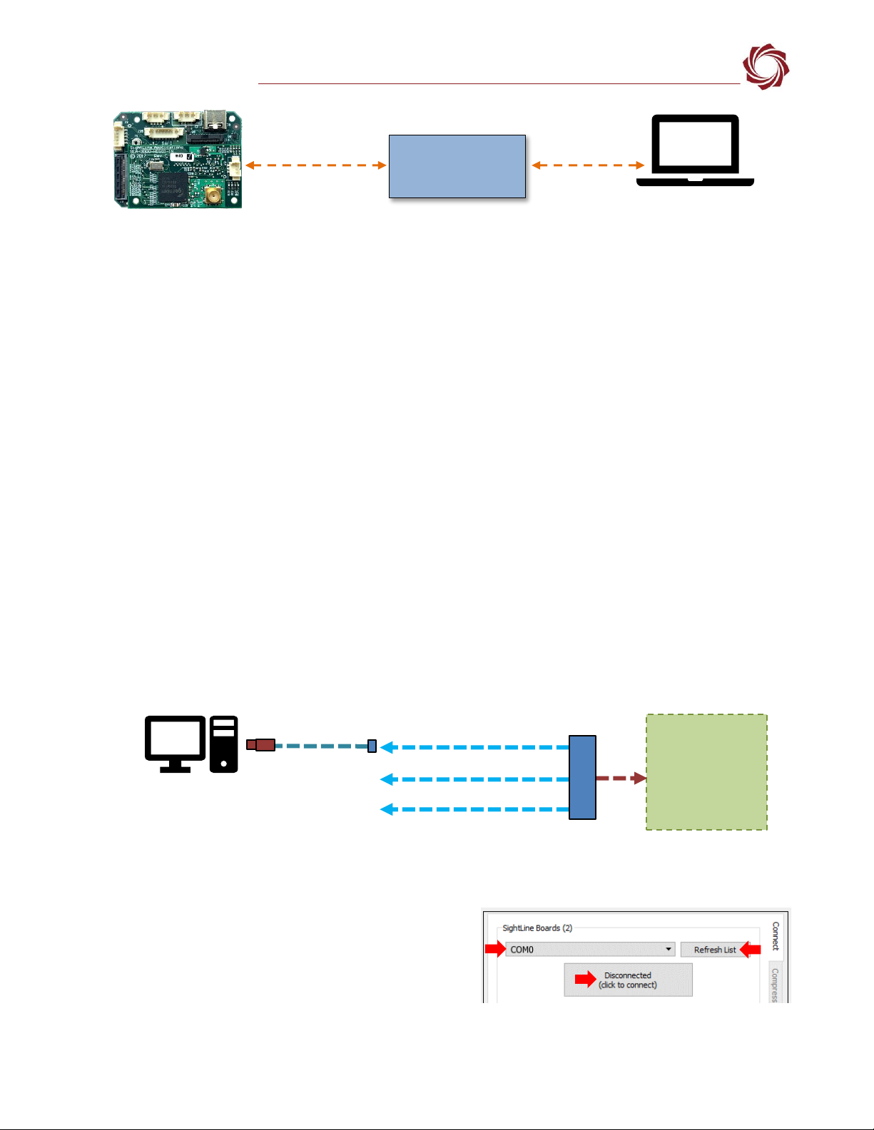
Figure 2: Network Configuration Options
5.1 Static IP Configuration Through Ethernet
1. Connect the board to a DHCP network.
2. Apply power to the 4000-OEM and wait for the board to receive an address from the DHCP server.
3. Connect to the board in Panel Plus.
4. Configure a static IP address using the procedure outlined in EAN-Network-Configuration.
Configuration notes:
•If a wireless adapter is active on the host PC it should be disabled.
•If using the link local address, we recommend assigning a static IP address to the host PC of
169.254.X.X, where X is 1-254 (do not use 182). Use a subnet mask of 255.255.0.0.
•Problems with outbound streaming are often related to setting/assigning IP addresses and ports.
See the Encoding Configuration settings in EAN-Encoding for advanced settings.
6Serial Communications
Use a direct serial connection for troubleshooting or if a network connection cannot be established.
To connect to a PC USB port, attach the USB to TTL (3.3V) serial cable (SLA-CAB-0305) to SLA-CAB-0804
to J25 (Serial 0) on the 4000-OEM board (Figure 3). Serial ports on the 4000-OEM are 3.3V TTL.
Figure 3: J25 Serial 0 to PC Connection (SLA-CAB-0804)
6.1 Direct Serial Connection (optional):
1. Connect the serial cable to the 4000-OEM board
and host PC as show in Serial Communications.
2. From the Connect tab, click the Refresh List button
to get a list of available COM ports.
3. Select the Com port in the drop-down menu.
4. Click the Disconnected (click to connect) button.
Figure 4: Direct Serial Connection
Host PC
User assigned static
IP: 169.254.1.10
4000-OEM Board
Ethernet Cable
Default IP assigned to the 4000-
OEM: 169.254.1.182
Network Switch
or PC Direct
J25 (8-pin)
Serial 0
3-pin Connector
SLA-CAB-0305
USB to PC*
SLA-CAB-0804
Serial 0
4000-OEM
*See the USB Device Driver
section below.
EAN- Startup Guide 4000-OEM
© SightLine Applications, Inc. 5
6.2 USB Device Driver
If the USB connection on SLA-CAB-0305 is not functioning correctly a third-party driver may be needed.
The driver can be found on the Silicon Labs web page » Downloads tab » CP210x Universal Windows
Driver. Once installed open the Run window in Windows (WIN+R) and enter devmgmt.msc to open the
Device Manager. Verify the new driver is listed under Ports (COM & LPT) as shown in Figure 5.
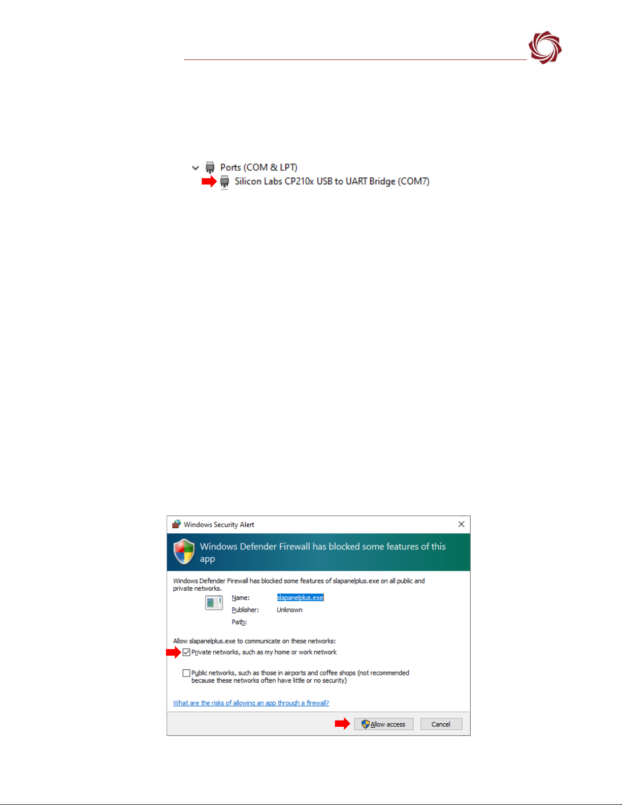
Figure 5: CP210x Universal Windows Driver Installed
7Panel Plus
This section covers the Panel Plus setup and configuration process. Panel Plus provides a basic
graphical interface to the 4000-OEM board.
Before connecting with the Panel Plus software, the 4000-OEM board should be powered up and
connected through:
-a network switch or directly to the host PC (preferred) or,
-Direct serial connection (for troubleshooting or if a network connection cannot be established).
1. Go to the Software Downloads page on the SightLine website and download the Panel Plus
application installer. Older releases are available under the Previous Versions section.
IMPORTANT: The firmware version number and Panel Plus Software version number should match.
If the board firmware version is initially unknown, reference the SightLine invoice that came with
the board when it was purchased.
2. Launch the installer file and follow the prompts. After installation, open the Panel Plus application.
3. The first time that Panel Plus is launched, a Windows Security Alert prompt should appear. Select
Allow Access to create a firewall exception (Figure 6).
Approving private network access is sufficient in most cases. Check public networks if directly
connecting to the board.
Figure 6: Windows Security Alert Prompt
C:\Program Files (x86)\sightline applications\sla-panel-plus
3.05.03\slapanelplus.exe
EAN- Startup Guide 4000-OEM
© SightLine Applications, Inc. 6
IMPORTANT:
•Do not cancel this prompt. Failure to allow access at this point will not allow the Panel Plus
application to connect to the board. See the Troubleshooting section for more information.
•Before using the Panel Plus program, review the Panel Plus User Guide in the Help section of the
Panel Plus application for additional user and setup information.
4. Network connection to the board:
a. From the Connect tab, click the Refresh List button to get a list of boards on the network.
b. Select the appropriate board in the drop-down menu.
c. Click the Disconnected (click to connect) button.
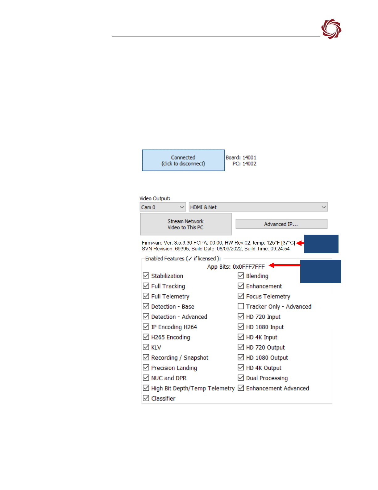
Once the connection is
successful, the button
changes to Connected.
Figure 7: Network Connection to the OEM Board
5. Verify the connection.
When the Panel Plus has
successfully connected to
the 4000-OEM board,
operating information is
displayed under the Video
Output section and the
bottom status bar in Panel
Plus. If the connection was
not successful, this
information will not be
present or incomplete.
IMPORTANT: For optimal
performance, monitor the
board temperature. Board
temperatures should be
below 185°F (85°C). To
keep boards within the
optimal temperature
range, use the included
heatsink during bench
testing. For more
information about thermal
management see the ICD-
4000-OEM.
Figure 8: Firmware Version and Enabled Features
Appbit code
with listed
features
Operating
information
EAN- Startup Guide 4000-OEM
© SightLine Applications, Inc. 7
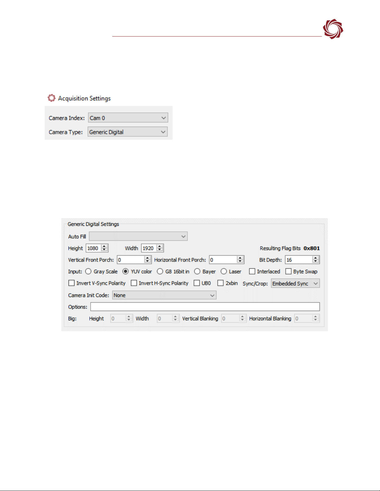
7.1 Camera Acquisition
1. From the main menu go to Configure »Aquisition Settings. This dialog window allows changes to
the camera configuration.
2. Set the Camera Index to Cam 0. Set the Camera Type to Generic Digital.
3. In the AutoFill drop-down menu, select HD-SDI 1080p30 from the Auto Fill menu or enter the
Height and Width settings of the connected camera.
If using a camera that is not configured for 1080p30, choose a corresponding option under Auto Fill
that matches the camera, e.g., HD-SDI 720p or HD-SDI 1080p60.
If the camera is listed, the AutoFill drop-down menu automatically populates the relevant fields with
the correct settings as shown in Figure 9.
Figure 9: Camera Acquisition Auto Fill Settings Example - HD-SDI 1080p30
4. After changes have been made, the Apply button will turn red indicating that a change has been
detected. Click Apply to apply the changes. Close the Acquisition Settings dialog window.
5. Save and activate the settings:
a. Main menu » Parameters » Save to Board.
b. Main menu » Reset » Board.
c. After the system reboots reconnect to the board. Make sure the board connects.
See EAN-Camera Compatibility for all third-party cameras and lens assemblies that are currently
supported by SightLine software. Includes configuration and setting support guidance.
EAN- Startup Guide 4000-OEM
© SightLine Applications, Inc. 8
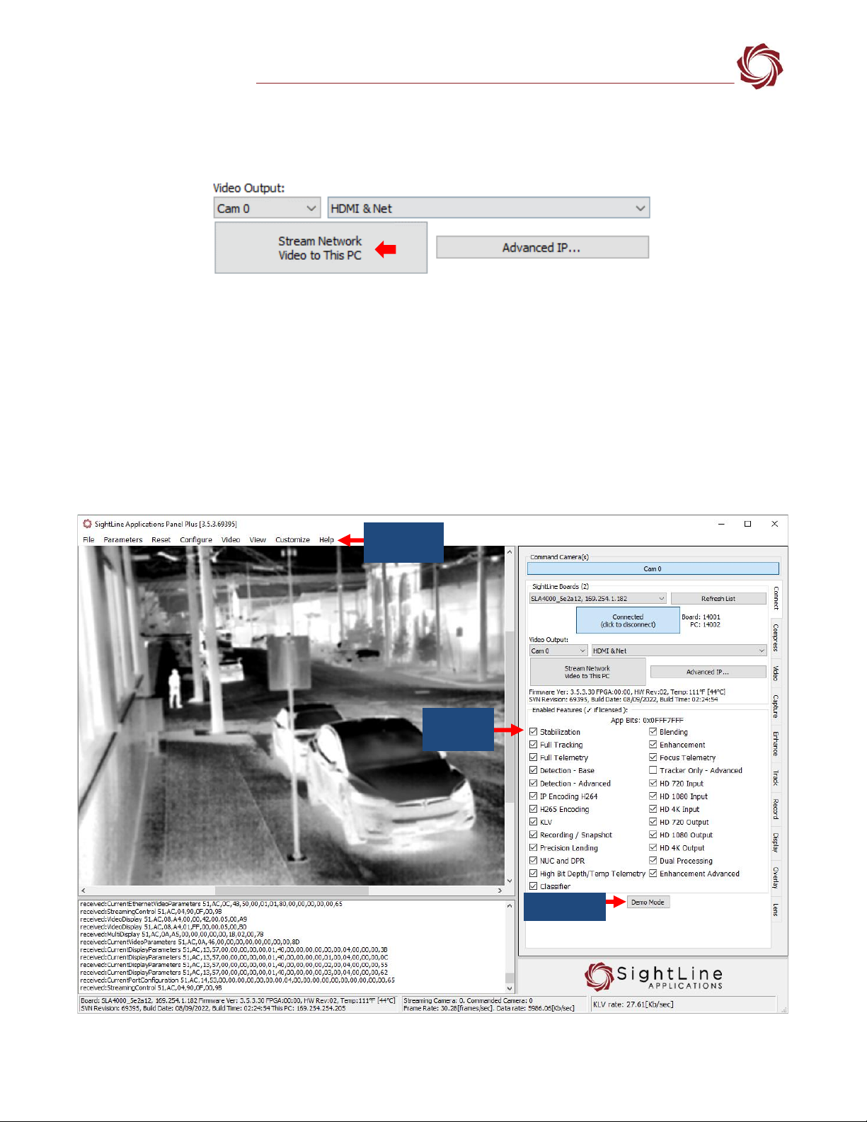
7.2 Stream Network Video to This PC
To stream network video to the connected PC, click the Connection tab in Panel Plus and then click
Stream Network Video to this PC.
Figure 10: Stream Network Video to PC
8Summary
This completes the startup guide for the 4000-OEM board. See the Panel Plus User Guide (main menu »
Help » User Guide) for additional user and setup information.
If the board has been connected to a camera and encoding functions are part of the configuration,
video will be displayed in the main window. On the Connect tab of Panel Plus, the purchased/enabled
functions are checked. To add additional features to 4000-OEM, contact Sales.
To modify the encoder parameters of the OEM, see the Modifying Encoder Parameters section.
Figure 11: Panel Plus Connection to Board
Enabled
Features
Panel Plus
User Guide
Demo Mode

EAN- Startup Guide 4000-OEM
© SightLine Applications, Inc. 9
IMPORTANT: Not all 4000-OEM purchased configurations include encoded IP video. For
configurations that include encoding, video will be displayed in the Panel Plus main window.
Tracker-only configurations will display processed video on the HDMI output only. An HDMI-
capable monitor is required for viewing this output.
8.1 Demo Mode
To enable all features for testing and evaluation purposes, click the Demo Mode button from the
Connect tab. All the features enabled on the board are now available for testing. The Demo Mode
screen overlay will display until the Demo Mode function is turned off.
9Modifying Encoder Parameters
The encoder parameters can be
modified from the Compress tab in
Panel Plus.
•The H.264 encoding option is a
good choice to get started.
•In the Output Properties section,
use the default values for Frame
Step and Down Sample.
•The Streaming parameters
section defines the destination
IP address and port.
•To set the parameters quickly,
click the Use My IP - Unicast
button. This sets the outbound
destination IP address to the
network interface card on the
PC.
•Click Send to dynamically set the
desired IP Address, UDP Port,
and UDP delivery format
(Unicast, Multicast, or
Broadcast).
•To save the settings and make
them recurrent through restarts,
main menu » Parameters » Save
to board.
See EAN-Parameter File for a
comprehensive guide to saving
parameter settings.
Figure 12: Compress Tab

EAN- Startup Guide 4000-OEM
© SightLine Applications, Inc. 10
10 Troubleshooting
Issue: Unable to connect with the Panel Plus application to the 4000-OEM over a standard network
connection.
Check static IP address:
Check the static IP address configuration. Improper or unknown static IP address setup is a common
connection problem. See the Network Configuration section and EAN-Network Configuration for more
network configuration information.
Check Windows firewall:
Failure to allow access in the Windows Security Alert dialog during initial startup of the Panel Plus
application can cause connection issues.
1. Close the Panel Plus software application and open the Windows Firewall Security Manager on the
host PC.
2. Go to Inbound rules and delete the two slapanelplus rules (TCP and UDP).
Figure 13: Windows Firewall Security Manager Fire - Delete Inbound Rules
3. Re-start the Panel Plus application and allow access in the Windows Security Alert prompt window.
Check hardware connections:
Make sure that all the boards are powered on. If connecting over the network, switch to a direct serial
connection. See the Serial Communications section. The Panel Plus software will automatically
recognize serial ports and list them in the drop-down menu for available connections.
Connecting to the serial port on the 4000-OEM board from a host PC requires TTL (3.3V) to USB
serial cable w/ 3-pin Molex cable (SLA-CAB-0305).
Delete inbound rules
EAN- Startup Guide 4000-OEM
© SightLine Applications, Inc. 11
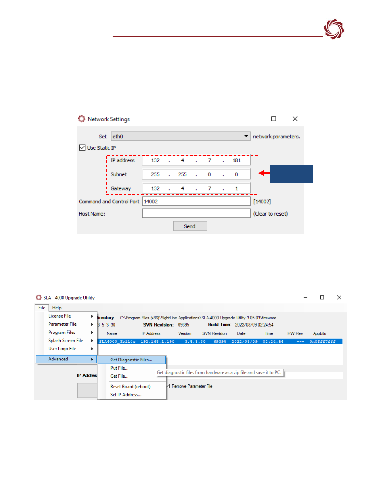
Check network configuration:
After communications have been established using the serial connection, networking settings can be
corrected to allow proper network communications.
1. From the main menu, go to Configure » Network Settings.
2. If an unknown static IP address is assigned, remove it or update it to match the addressing scheme
of your network.
Figure 14: Check Network Settings
10.1 Send Diagnostic Files to SightLine Support
In the event of a system malfunction or other issue, use the Get Diagnostic Files feature in the
SightLine upgrade utility application to download files and then send them to Support.
Figure 15: Get Diagnostic Files
Additional diagnostic information can also be obtained from the 4000-OEM by displaying the system
log.
1. Establish an SSH session to the OEM with Tera Term (recommended) or similar application.
2. Login using the default username and password for the 4000-OEM: slroot
Check network
settings
EAN- Startup Guide 4000-OEM
© SightLine Applications, Inc. 12
3. At the prompt, type:
dmesg
4. Copy the output and send it to Support.
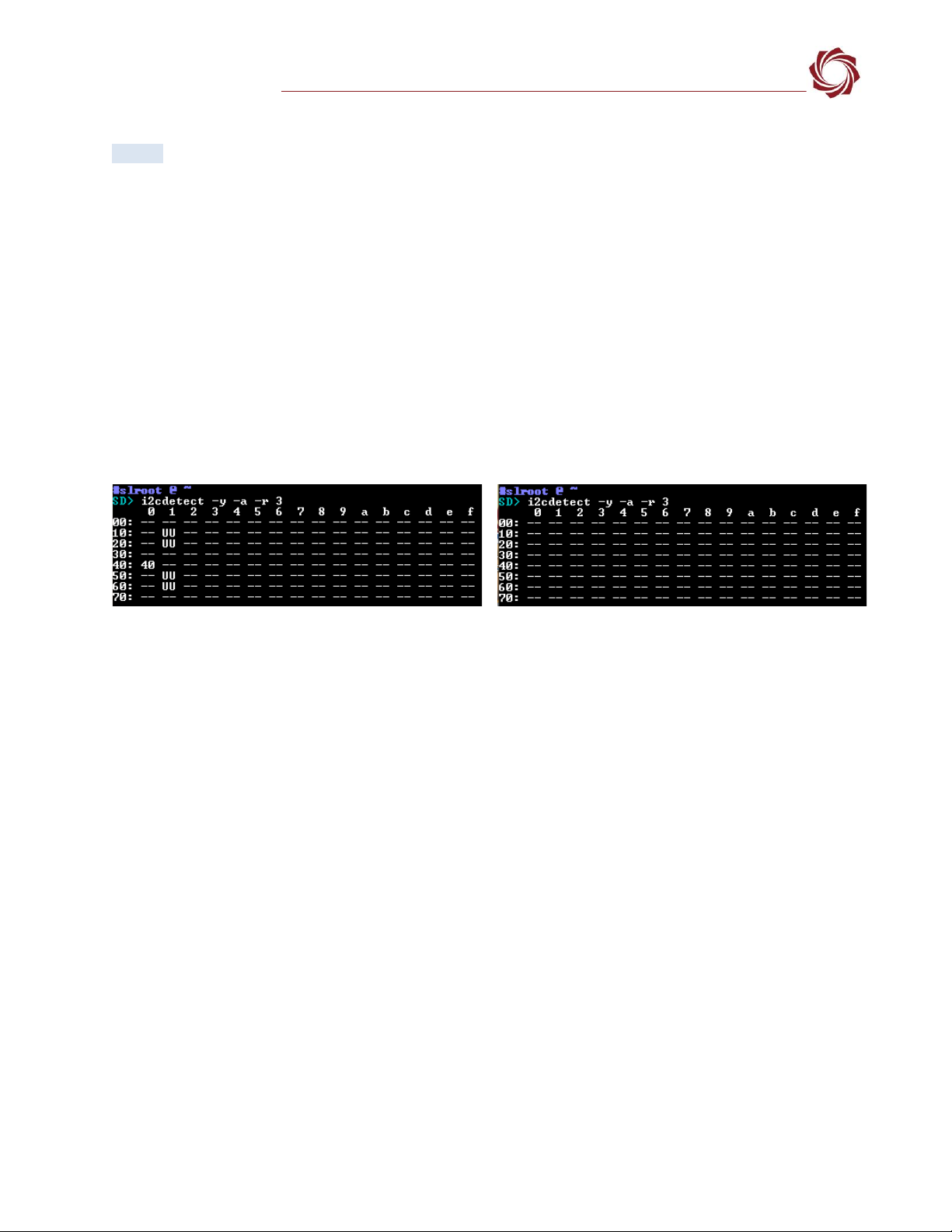
10.2 Nonfunctional SLA-4000-MIPI-IN Board (4000-MIPI-IN Kit)
I2C Bus 3 detect can be used to help diagnose issues with ports and/or cable connections on the SLA-
4000-MIPI-IN board.
1. Remove all the adapter boards from the 4000-OEM.
2. Establish an SSH session to the 4000-OEM with Tera Term (recommended) or similar application.
Username and password: slroot
3. Run command: i2cdetect -y -a -r 3. The status of the SLA-4000-MIPI-IN board in Tera Term is shown
in Figure 12.
Figure 16: I2C Bus 3 Detect with Tera Term
4. If nothing shows up using I2C Bus 3 detect, check the SLA-CAB-MIPI-02 cable connection between
the SLA-4000-IN MIPI board and the 4000-OEM, and then repeat steps 1 through 3.
IMPORTANT: To prevent damage to hardware boards, disconnect the power before connecting or
disconnecting the SLA-CAB-MIPI-02 cable.
5. If the board is still not responding contact SightLine Support.
10.3 Questions and Additional Support
For questions and additional support, please contact SightLine Support. Additional support
documentation and Engineering Application Notes (EANs) can be found on the Documentation page of
the SightLine Applications website.
Functioning and Connected Correctly
Not Functioning and/or Connected Correctly
Table of contents
Other SightLine Media Converter manuals


