1-4
Break-In Procedure
A new vehicle and an overhauled engine require a
“break-in” period. The first 10 hours (or 200 miles) are
most critical to the life of this vehicle. Proper opera-
tion during this break-in period will help assure maxi-
mum life and performance from the vehicle.
During the first 10 hours (or 200 miles) of operation,
always use less than 1/2 throttle. Varying the engine
RPM during the break-in period allows the compo-
nents to “load” (aiding the mating process) and then
“unload” (allowing components to cool). Although it
is essential to place some stress on the engine compo-
nents during break-in, care should be taken not to
overload the engine too often. Do not pull a trailer or
carry heavy loads during the 10-hour break-in period.
When the engine starts, allow it to warm up properly.
Idle the engine several minutes until the engine has
reached normal operating temperature. Do not idle the
engine for excessively long periods of time.
During the break-in period, a maximum of 1/2 throttle
is recommended; however, brief full-throttle accelera-
tions and variations in driving speeds contribute to
good engine break-in.
After the completion of the break-in period, the engine
oil and oil filter should be changed. Other maintenance
after break-in should include checking of all pre-
scribed adjustments and tightening of all fasteners.
Gasoline - Oil -
Lubricant
RECOMMENDED GASOLINE
The recommended gasoline to use is 87 minimum
octane regular unleaded. In many areas, oxygenates
(either ethanol or MTBE) are added to the gasoline.
Oxygenated gasolines containing up to 10% ethanol,
5% methane, or 5% MTBE are acceptable gasolines.
When using ethanol blended gasoline, it is not neces-
sary to add a gasoline antifreeze since ethanol will pre-
vent the accumulation of moisture in the fuel system.
RECOMMENDED ENGINE/
TRANSMISSION OIL
The recommended oil to use is Arctic Cat 4-Cycle
Engine Oil or an equivalent oil which is rated SE, SF,
or SG under API service classification. These oils
meet all of the lubrication requirements of the Arctic
Cat engine. The recommended engine oil viscosity is
SAE 5W-30. Ambient temperature should determine
the correct weight of oil. See the following viscosity
chart for details.
OILCHARTC
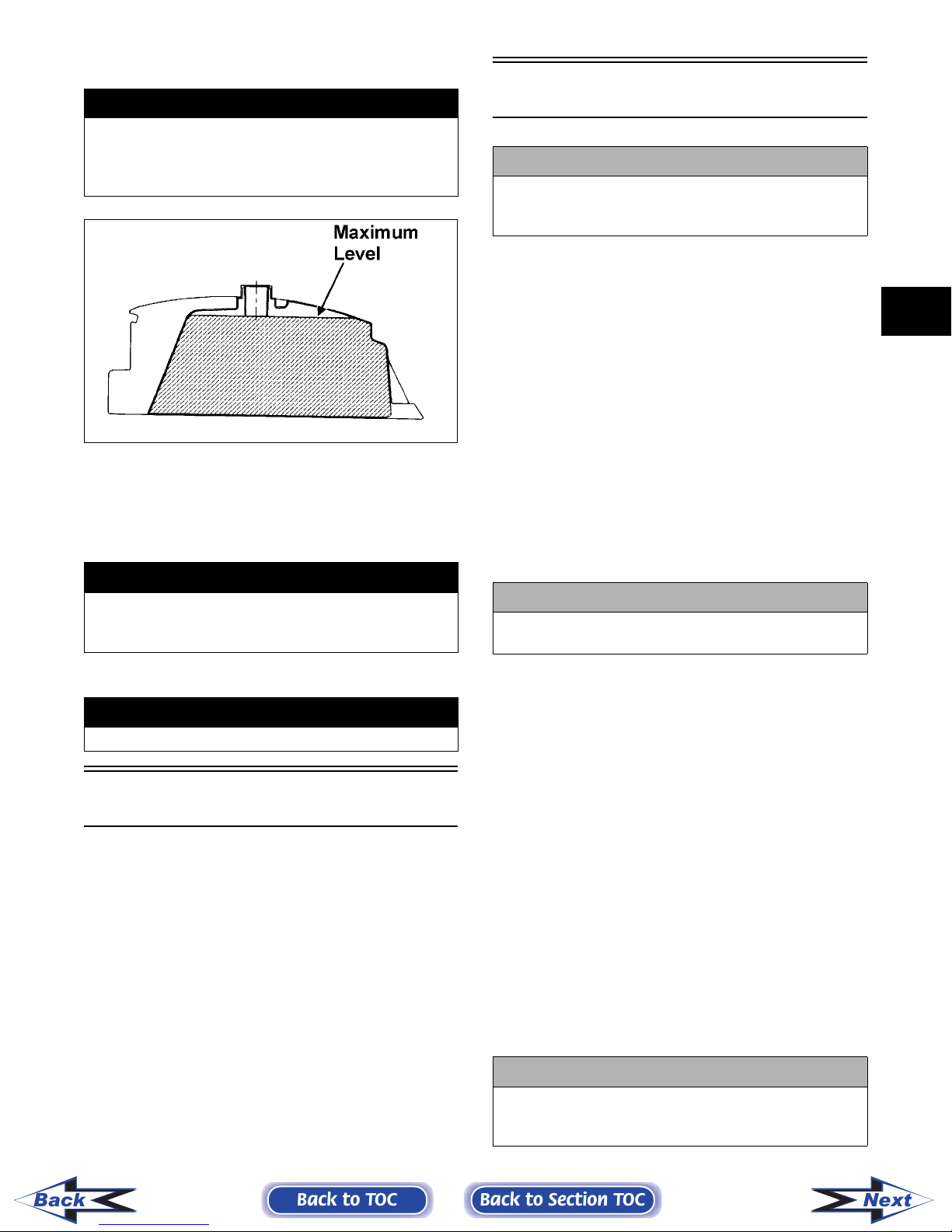
RECOMMENDED FRONT
DIFFERENTIAL/REAR DRIVE
LUBRICANT
The recommended lubricant is Arctic Cat Gear Lube
or an equivalent gear lube which is SAE approved
80W-90 hypoid. This lubricant meets all of the lubrica-
tion requirements of the Arctic Cat vehicle front differ-
ential and rear drive.
! CAUTION
Do not use white gas. Only Arctic Cat approved gas-
oline additives should be used.
! CAUTION
Any oil used in place of the recommended oil could
cause serious engine damage. Do not use oils which
contain graphite or molybdenum additives. These
oils can adversely affect clutch operation. Also, not
recommended are racing, vegetable, non-detergent,
and castor-based oils.
! CAUTION
Any lubricant used in place of the recommended
lubricant could cause serious front differential/rear
drive damage.
Back to TOC Back to Section TOC Next
Back