manuals.online logo
Brands
  1. Home
  2. •
  3. Brands
  4. •
  5. Arecont Vision
  6. •
  7. Security Camera
  8. •
  9. Arecont Vision D4SO Series User manual

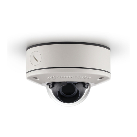
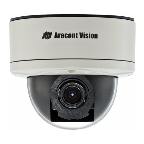
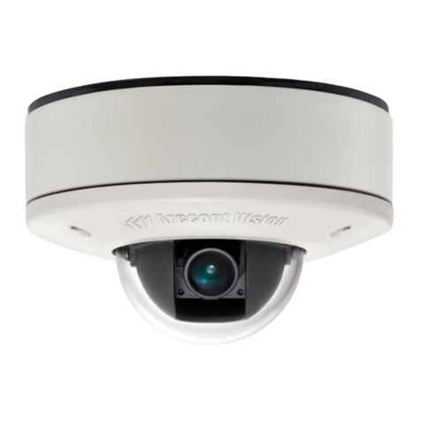
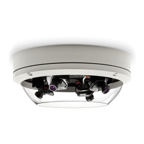
Arecont Vision D4SO Series User manual

Arecont Vision D4SO Outdoor Dome Series Installation Manual
0 | Page
Arecont Vision D4SO Outdoor Dome Series Installation Manual
1 | Page
D4SO Outdoor Dome Installation Manual
A. Arecont Vision D4SO Dome Camera
Inside the box:
B. Mounting template
C. Security L-key
D. One double sided hex key
E. One single sided hex key
F. 6-position external power & IO plug
G. Pack of four (4) wood screws and four (4)
dry wall anchors
•#1 Phillips head screw driver
Not included but needed:
•#2 Phillips head screw driver
•Small Flat Head screw driver
Image 1
Mounting the Camera:
1. Remove camera and hardware from the
box.
2. Using the Mounting Template, prepare
the mounting provisions for camera
installation. NOTE: the 19.5mm diameter
hole on the Mounting template is where
the Ethernet cable will be exiting the
D4SO, align accordingly. If using the
side conduit hole, please see step 7
below.
3. Using Security L-key, loosen the four (4)
screws securing the dome cover (Image
2). Remove vandal resistant dome
cover. NOTE: Do not remove screws
from the dome cover.
Image 2
G
F
E
C
A
D
B
Arecont Vision D4SO Outdoor Dome Series Installation Manual
2 | Page
4. Run Ethernet cable through the hole on the
bottom of D4SO and plug it into the RJ45 port
on Arecont Vision’s compact MegaVideo®
camera. (Image 3) . NOTE: If the camera will
be powered via PoE, please skip to step 5.
Image 3
5. If the camera is powered by an outside power
supply, run power wires through the hole and
connect power wires to appropriate contacts
of 6-postion connector using small flat screw
driver and connect 6-position plug to camera
as shown in Image 4-1.
Note: Please make sure the polarity of the
AC/DC input on the camera match the way
wires are installed in connector shown in
Image 4-2.
Image 4-1
Image 4-2
6. Align the holes in the camera with the
prepared holes on the mounting surface.
Attach the camera to the mounting surface
with the wood screws or any optional
hardware suitable for the mounting surface.
Arecont Vision D4SO Outdoor Dome Series Installation Manual
3 | Page
7. If you are using the side conduit opening,
remove the conduit plug by first removing the
socket set screw using one of provided Allen
keys (Image 5).
Image 5
8. To adjust the tilt, use a #1 Phillips screwdriver
to loosen the screw on the side of the U
bracket 1/4 turn (Image 6). CAUTION: Do not
remove the screw!
Adjusting the Tilt and Pan:
Image 6
9. Adjust lens tilt as required and tighten the
screw. CAUTION: To properly install camera,
the U bracket needs to be installed between
the dome BASE and camera Bubble shown
in Image 7
Image 7
10. To adjust the pan, hold and turn the U bracket
as shown in Image 8.
Image 8
0°
90°
Screw
Gimbal Base
Pan=360°
U Bracket
Arecont Vision D4SO Outdoor Dome Series Installation Manual
4 | Page
11. To focus the lens, loosen the three set screws
as shown in Image 9and adjust each as
needed. Aadjusts the zoom, Badjusts the
iris, Cadjusts the focus.
Adjusting the Focus:
Note: Adjust zoom first then focus!
Note: For more information on proper
focusing technique, please watch the
“Focusing Arecont Vision Megapixel
Cameras” Best Practices Training Video at
www.youtube.com/ArecontVision.
12. Secure the dome cover to the camera.
13. Tighten the set screw on the dome cover.
14. Rotate bubble to align camera with slot in
camera shield.
15. Remove the protective film from the camera
dome. NOTE: be cautious not to scratch the
vandal dome cover.
Image 9
B
A
C
Arecont Vision D4SO Outdoor Dome Series Installation Manual
5 | Page
D4SO Pendant Mount (MD-CMT) Installation Instructions
A. Top shield
Inside the box:
B. Pendant Mount
C. Mounting template
D. Pack of four (4) machine screws
E. Pack of four (4) small machine screws
F. Pack of four (4) wood screws and four (4)
dry wall anchors
G. Large round rubber gasket
H. Smaller square rubber gasket
I. One double sided hex key
•#2 Phillips head screw driver
Not included but needed:
Image 10
1. Remove Pendant Mount and hardware from
the box.
Image 11 Image 12
2. Using the Mounting template, prepare the
mounting provisions for camera installation.
3. Place small gasket onto pendant dome as
shown in image 11.
4. Attach Dome to Pendant as shown in Image
12 using four machine screws provided.
5. Install large round rubber gasket onto
Pendant as shown in image 12. Be sure to
align the holes appropriately.
6. Run Ethernet Cable and outside power cable
(if necessary) through the Pendant.
7. Attach Pendant to the ceiling using the four
wood screws provided or any optional
hardware suitable for the mounting surface.
8. For installation of the camera, please
reference “Mounting the Camera”.
E
C
H
G
D
B
A
I
F
Arecont Vision D4SO Outdoor Dome Series Installation Manual
6 | Page
D4SO Wall Mount (MD-WMT2) Installation Instructions
MD-WMT2 only fits with SV-JBA and SV-EBA but
not with MD-JBA and MD-EBA!
Caution:
A. Wall mount ( Fit 1.5 NPT Standard)
Inside the box:
B. Top shield
C. Mounting template
D. One double sided hex key
E. Pack of four (4) machine screws
F. Pack of four (4) wood screws and four (4)
dry wall anchors
•#2 Phillips head screw driver
Not included but needed:
Image 13
1. Remove Wall Mount and hardware from the
box.
Image 14
2. Using the Mounting template, prepare the
mounting surface.
3. Install Top Shield on Wall Mount as shown in
image 14.
4. Fasten the socket set screw using double side
hex key.
5. Run Ethernet Cable and outside power cable
(if necessary) through the Wall Mount.
6. Attach Wall Mount to the wall using drywall
screws or any optional hardware suitable for
the mounting surface.
7. For installation of the camera, please
reference “Mounting the Camera”.
B
E
D
C
A
F
Arecont Vision D4SO Outdoor Dome Series Installation Manual
7 | Page
D4SO Wall Mount Cap (MD-CAP) Installation Instructions
A. Wall Mount Cap (MD-CAP)
Inside the box:
B. Pack of four (4) machine screws
•1½” NPT Pipe
Not included but needed:
•1½” NPT Coupling
•1½” NPT Flange
•#2 Phillips head screw driver
Image 15
1. Remove Wall Mount Cap from the box.
2. Assemble Wall Mount Cap, 1½” Coupling,
1½” Pipe nipple and 1½” Flange as a Pendant
Mount shown in image 16.
Image 16
3. Run Ethernet Cable and outside power cable
(if necessary) through the Pendant.
4. Attach Pendant to the ceiling using four wood
screws or any optional hardware suitable for
the mounting surface
5. For installation of the camera, please
reference “Mounting the Camera”.
A
MD-CAP
1 ½” Coupling
1 ½” Pipe
1 ½” Flange
B
Arecont Vision D4SO Outdoor Dome Series Installation Manual
8 | Page
D4SO Junction Box Adapter (MD-JBA) Installation Instruction
MD-JBA only fits with D4SO and MD-CMT but not
with MD-WMT2!
Caution:
A. Junction Box Adapter
Inside the box:
B. Large round rubber gasket
C. Pack of four (4) wood screws and four (4)
dry wall anchors
D. Pack of four (4) machine screws
E. One double sided hex key
•#2 Phillips head screw driver
Not included but needed:
•D4SO Wall Mount, MD-WMT
•¾” NPT Conduit (if necessary)
Image 17
1. Remove Junction Box and hardware from the
box
Image 18Image 19
2. Remove the conduit plug by first removing the
socket set screw using one of provided Allen
keys shown in Image 18.
3. Attach Junction Box Adapter to the wall using
drywall screws or any optional hardware
suitable for the mounting surface.
4. Attach D4SO Wall Mount to Junction Box
Adapter as shown in Image 19.
5. Connect ¾” NPT Conduit to Junction Box
Adapter
6. Run Ethernet Cable and outside power cable (if
necessary) through the Junction Box Adapter
and Wall Mount.
7. For installation of the camera, please
reference “Mounting the Camera”.
B
C
A
D
E
Arecont Vision D4SO Outdoor Dome Series Installation Manual
9 | Page
D4SO Junction Box Adapter (SV-JBA) for MD-WMT2 Installation Instruction
SV-JBA only fits with MD-WMT2 but not with D4SO
and MD-CMT!
Caution:
A. Junction Box Adapter
Inside the box:
B. Pack of four (4) machine screws
C. One double sided hex key
D. Pack of four (4) wood screws and four (4)
dry wall anchors
E. Large round rubber gasket
•#2 Phillips head screw driver
Not included but needed:
•D4SO Wall Mount, MD-WMT
•¾” NPT Conduit (if necessary)
Image 20
1. Remove Junction Box and hardware from the
box
Image 21
2. Remove the conduit plug by first removing the
socket set screw using one of provided Allen
keys.
3. Attach Junction Box Adapter to the wall using
drywall screws or any optional hardware
suitable for the mounting surface.
4. Attach D4SO Wall Mount to Junction Box
Adapter as shown in Image 21.
5. Connect ¾” NPT Conduit to Junction Box
Adapter.
6. Run Ethernet Cable and outside power cable (if
necessary) through the Junction Box Adapter
and Wall Mount.
7. For installation of the camera, please
reference “Mounting the Camera”.
B
C
A
D
E
Arecont Vision D4SO Outdoor Dome Series Installation Manual
10 | Page
D4SO Flush Mount Adapter (MD-FMA) Installation Instructions
A. White Trim Ring
Inside the box:
B. Flush Mount Adapter
C. Mounting template
D. Pack of four (4) machine screws and one
(1) I-Blot
•#2 Phillips head screw driver
Not included but needed:
Image 22
1. Remove Flush Mount Adapter, Trim Ring and
hardware from the box.
2. Attach Dome to Flush Mount Adapter as
shown in Image 23. Please reference
“Mounting the Camera”, if needed.
3. Using the Mounting template, cut a hole in
surface for mounting.
4. Insert Flush Mount Adapter into the hole.
5. Screw the “lever screws” until the FMA is
snuggly installed, as shown in Image 23. The
“Support Arm” will ride down the screw to
compress the mounting surface.NOTE: Do
not over-torque the lever screws
6. Attach the Trim Ring to the Flush Mount Adapter
by rotating clockwise as show in Image 24.
Image 23
Image 24
B
C
A
Lever
screw
D
Support
Arm
Arecont Vision D4SO Outdoor Dome Series Installation Manual
11 | Page
D4SO Electrical Box Adapter (MD-EBA) Installation Instructions
MD-EBA fits with D4SO and MD-CMT but not with
MD-WMT2!
Caution:
A. Electrical Box Adapter
Inside the box:
B. Pack of four (4) machine screws
•#2 Phillips head screw driver
Not included but needed:
•Common Electrical Box, such as single
gang box, double gang box or square
electrical box.
Image 25
1. Remove Electrical Box Adapter and hardware
from the box.
2. Match mounting holes on adapter with thread
holes on the electrical box, make sure every
threaded hole is matched with mounting hole.
3. Attach Electrical Box Adapter to Electrical Box
as shown in Image 26.
4. Attach Dome to Electrical Box Adapter as
shown in Image 27. Please reference
“Mounting the Camera”, if needed.
Image 26
Image 27
B
A
Arecont Vision D4SO Outdoor Dome Series Installation Manual
12 | Page
D4SO Electrical Box Adapter (SV-EBA) for SV-WMT2 Installation Instructions
SV-EBA fits with MD-WMT2 but not with D4SO and
MD-CMT!
Caution:
A. Electrical Box Adapter
Inside the box:
B. Pack of four (4) machine screws
•#2 Phillips head screw driver
Not included but needed:
•Common Electrical Box, such as single
gang box, double gang box or square
electrical box.
Image 28
1. Remove Electrical Box Adapter and hardware
from the box.
2. Match mounting holes on adapter with thread
holes on the electrical box, make sure every
threaded hole is matched with mounting hole.
3. Attach Electrical Box Adapter to Electrical Box.
4. Attach Dome to Electrical Box Adapter as
shown in Image 29. Please reference
“Mounting the Camera”, if needed.
Image 29
B
A
Arecont Vision D4SO Outdoor Dome Series Installation Manual
13 | Page
D4SO Pole Mount Adapter (MD-PMA) Installation Instructions
A. Pole Mount Adapter
Inside the box:
B. 2x Compress Fittings
C. 2x Small Steel Straps
D. 2x Large Steel Straps
E. Pack of four (4) machine screws
•#2 Phillips head screw driver
Not included but needed:
•D4SO Wall Mount Adapter
Image 30
1. Remove Pole Mount Adapter, Compress
Fittings, Steel Straps and hardware from the
box.
2. Install Compress Fittings to Pole Mount
Adapter as shown in Image 31.
3. Attach D4SO Wall Mount Adapter to Pole
Mount Adapter as shown in Image 32.
4. Run Ethernet Cable and outside power cable
(if necessary) through the Compress Fittings
and D4SO Wall Mount.
5. Use the supplied two Steel Straps to attach
the Pole Mount Adapter to the pole and
tighten the compression screws as shown in
Image 32.
6. Attach Dome to Wall Mount Adapter. Please
reference “Mounting the Camera”, if needed.
7. Tighten the Compress Fittings to seal the
wiring holes.
Image 31
Image 32
A
B
C
D
E
Wall
Mount
Adapter
Compression
Screws
Arecont Vision D4SO Outdoor Dome Series Installation Manual
14 | Page
D4SO Corner Mount Adapter (MD-CRMA) Installation Instructions
A. Corner Mount Adapter
Inside the box:
B. 2x Compression Fittings
C. Pack of four (4) machine screws
D. 2x Packs of four (4) wood screws and four
(4) dry wall anchors
•#2 Phillips head screw driver
Not included but needed:
•D4SO Wall Mount Adapter
Image 33
1. Remove Corner Mount Adapter, Compress
Fitting and hardware from the box.
2. Install Compress Fittings to Corner Mount
Adapter as shown in Image 34.
3. Attach Wall Mount Adapter to Corner Mount
Adapter as shown in Image 35.
Image 34
Image 35
4. Run Ethernet Cable and outside power cable
(if necessary) through the Compress Fittings
and D4SO Wall Mount.
5. Using the screws provided (or other hardware)
attach the Corner Mount Adapter to an
exterior 90° corner wall.
6. Attach Dome to Wall Mount Adapter. Please
reference “Mounting the Camera”, if needed.
7. Tighten the Compress Fittings to seal the
wiring holes.
A
B
C
D
Arecont Vision D4SO Outdoor Dome Series Installation Manual
15 | Page
D4SO I/O Cable Connection
•Flat head screw driver
Not included but needed:
Image 36
1. To use the I/O ports of the D4SO, insert the
connector to Arecont Vision Compact camera
and locate the “I/O” parts as shown in Image
37. NOTE: There are six connectors that look
identical, be sure to use correct I/O ports
shown in Image 36.
Image 37
2. Run the I/O cable through the hole in the
bottom of the camera and plug it into the “J7”
connector as shown in image 33. NOTE: The
connection is a little stiff so be sure to apply
enough pressure to connect it; using a flat
head screw driver to push it in is
recommended.
Electrical Characteristics:
Min Max
Input voltage (V)
ON
2.9
6.3
(measured between + and –
terminals) OFF 0 1.3
Output current (mA)
ON
-
50
(measured between + and – terminals)
Applied Voltage Rage: 0 - 80V OFF - 0.1
Table 1
NOTE: Both the input and the output are electrically
isolated from the rest of the camera’s
electrical circuitry via general-purpose photo
couplers. The input is additionally protected
with a serial 250 Ohm resistor, and a
debouncing circuit. Duration of any input
signal should be at least 5 ms to comply with
the requirements of the debouncing circuit.
Orange
OUT +
Yellow
OUT –
White
IN +
Black
IN -
Table 2
Input
Output
Arecont Vision D4SO Outdoor Dome Series Installation Manual
16 | Page
D4SO Heater (MD-1HK) Accessory
A. Heater
Inside the box:
B. Two (2) screws
•#1 Phillips head screw driver
Not included but needed:
Image 38
1. Run the heater cable out of the hole in the
bottom of the camera and connect it to 10-
50VDC power supply. 10 Watts max. Red is
positive (+) cable.
2. Remove the heater kit from the box.
3. With the heater element protruding out of the
camera, align the two (2) holes on the heater
board with the two standoffs shown in Image
39.
4. Screw the heater board to the standoffs as
shown in Image 40.
Image 39
Image 40
B
A
Arecont Vision D4SO Outdoor Dome Series Installation Manual
17 | Page

Other manuals for D4SO Series

1

This manual suits for next models

1

Other Arecont Vision Security Camera manuals
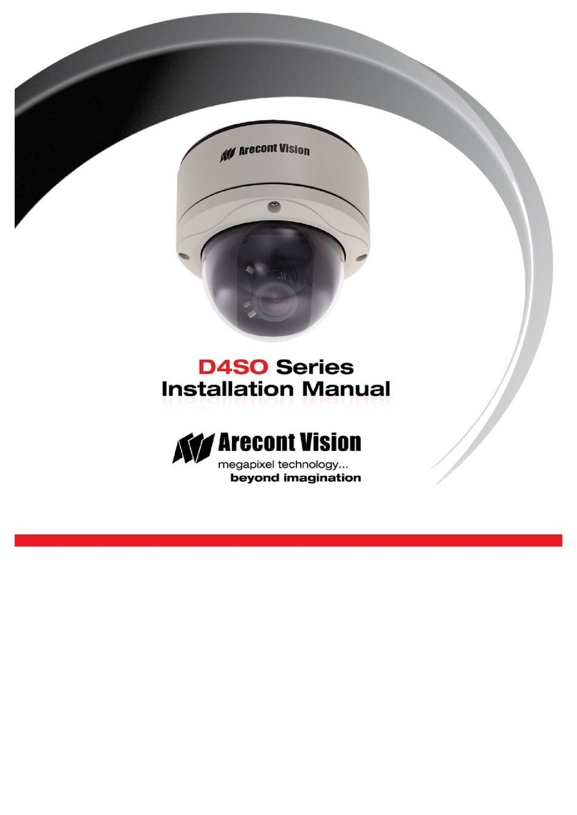
Arecont Vision MegaBall AV2245PM-W User manual

Arecont Vision

Arecont Vision MegaBall AV2245PM-W User manual

Arecont Vision MegaView v1x series User manual

Arecont Vision

Arecont Vision MegaView v1x series User manual

Arecont Vision AV12ZMV-301 User manual

Arecont Vision

Arecont Vision AV12ZMV-301 User manual

Arecont Vision MicroDome AV1455DN-F User manual

Arecont Vision

Arecont Vision MicroDome AV1455DN-F User manual

Arecont Vision MegaBall 2 User manual

Arecont Vision

Arecont Vision MegaBall 2 User manual

Arecont Vision D4S Series User manual

Arecont Vision

Arecont Vision D4S Series User manual

Arecont Vision Contera AV02CID-100 User manual

Arecont Vision

Arecont Vision Contera AV02CID-100 User manual

Arecont Vision SurroundVideo G5 Mini User manual

Arecont Vision

Arecont Vision SurroundVideo G5 Mini User manual

Arecont Vision AV2100 User manual

Arecont Vision

Arecont Vision AV2100 User manual

Arecont Vision SurroundVideo Omni AV12176DN-08 User manual

Arecont Vision

Arecont Vision SurroundVideo Omni AV12176DN-08 User manual

Arecont Vision AV08ZMV-300 User manual

Arecont Vision

Arecont Vision AV08ZMV-300 User manual

Arecont Vision AV12975DN-NL User manual

Arecont Vision

Arecont Vision AV12975DN-NL User manual

Arecont Vision MegaBall AV2245PM-W User manual

Arecont Vision

Arecont Vision MegaBall AV2245PM-W User manual

Arecont Vision MegaDome 2 User manual

Arecont Vision

Arecont Vision MegaDome 2 User manual

Arecont Vision MegaView 2 AV1225PMIR-S User manual

Arecont Vision

Arecont Vision MegaView 2 AV1225PMIR-S User manual

Arecont Vision AV2325DNIR User manual

Arecont Vision

Arecont Vision AV2325DNIR User manual

Arecont Vision D4S Series User manual

Arecont Vision

Arecont Vision D4S Series User manual

Arecont Vision AV1215PM-S User manual

Arecont Vision

Arecont Vision AV1215PM-S User manual

Arecont Vision ConteraIP Fisheye AV12CPD-236 User manual

Arecont Vision

Arecont Vision ConteraIP Fisheye AV12CPD-236 User manual

Arecont Vision D4SO Series User manual
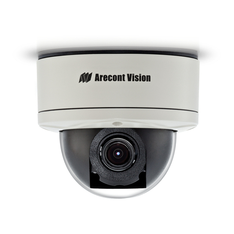
Arecont Vision

Arecont Vision D4SO Series User manual

Arecont Vision megadome User manual

Arecont Vision

Arecont Vision megadome User manual

Arecont Vision MicroDome G2 AV1555DN-S User manual
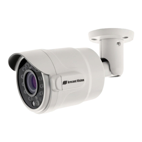
Arecont Vision

Arecont Vision MicroDome G2 AV1555DN-S User manual

Arecont Vision Contera AV02CLB-100 User manual
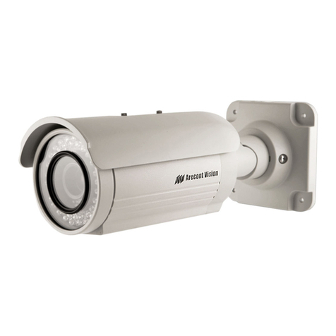
Arecont Vision

Arecont Vision Contera AV02CLB-100 User manual

Arecont Vision SurroundVideo Series User manual

Arecont Vision

Arecont Vision SurroundVideo Series User manual

Popular Security Camera manuals by other brands

ALC Connect Plus Faq

ALC

ALC Connect Plus Faq

Vitek VTC-B74 Specifications

Vitek

Vitek VTC-B74 Specifications

Channel Vision 6010 Specification sheet

Channel Vision

Channel Vision 6010 Specification sheet

COP-USA CH21C-2.5 Specifications

COP-USA

COP-USA CH21C-2.5 Specifications

Vicon V940B quick guide

Vicon

Vicon V940B quick guide

iVision IV-WP866PL user manual

iVision

iVision IV-WP866PL user manual

Okina USA HD5FEVD-8012 user manual

Okina USA

Okina USA HD5FEVD-8012 user manual

YI Dome X user manual

YI

YI Dome X user manual

Reolink E1 Zoom user manual

Reolink

Reolink E1 Zoom user manual

Eneo IED-62F0036M0A user manual

Eneo

Eneo IED-62F0036M0A user manual

Bolin Technology VCC-8-4K20S-3SM user manual

Bolin Technology

Bolin Technology VCC-8-4K20S-3SM user manual

Smartwares CIP-39901 Installation and operating instructions

Smartwares

Smartwares CIP-39901 Installation and operating instructions

Vivotek FE9382-EHV-v2 user manual

Vivotek

Vivotek FE9382-EHV-v2 user manual

SVAT VU301-C instruction manual

SVAT

SVAT VU301-C instruction manual

ARTRAY ARTCAM-KAI-USB3 Series Instruction booklet

ARTRAY

ARTRAY ARTCAM-KAI-USB3 Series Instruction booklet

Panasonic Super Dynamic III WV-CW974 Specifications

Panasonic

Panasonic Super Dynamic III WV-CW974 Specifications

Digitus DN-16055 user manual

Digitus

Digitus DN-16055 user manual

Wisenet HCD-7010R user manual

Wisenet

Wisenet HCD-7010R user manual

manuals.online logo
manuals.online logoBrands
  • About & Mission
  • Contact us
  • Privacy Policy
  • Terms and Conditions

Copyright 2025 Manuals.Online. All Rights Reserved.