Arena Luci AR3333--RGBWA User manual

PARLEDRGBWA
User'sManual
SpotLEDRGBWAIP65withDMXcontrol
AR3333RGBWA

2/12
AR3333RGBWA
This unit should only be used for purpose for
which it has been intended and should be
installed using the instructions which are
provided. Arena Luci cannot be held liable for
damages to person, animals or objects as a
result of improper, unreasonable and wrong
usage.
This instruction manual contains important
information about the installation and use of the
projector. Please read and follow these
instructionscarefully.
The security of this device is guaranteed only
with the proper use of the following instructions,
thereforetheymustbekeptcarefully.
Never install the device in locations easily
accessiblebypeoplewhoignoretheexistenceof
thisuser'smanualandsafetyinstructions.
For the wiring please refer to enclosed wiring
diagrams. If in the diagrams indicated there
shouldnotbethatofyourapplication,contactthe
technicaloffice.
Disconnecttheunitfromanypowersupplybefore
attempting any operation in contact or inside the
unit,andwhennotinuse.
It is essential that each device is correctly
earthedandthatelectricalinstallationconformsto
all relevant standards. Never supply the unit
withouttheearthlink.
Prior to connect the unit to the mains supply,
check the output voltage fits the technical
requirementsonthelabel.
Never let the power cord come into contact with
othercables.
Nevertouchtheelectricalcontacts,eitherdirectly
withyour fingers,orindirectly bymeansofsharp
ormetalobjects.
Makesurethatcablescannotcausetriphazard.
Donotattempttodismantleandmodifytheunit.
Due to the high technological level of this unit,
anyservicemaintenanceshouldbeperformedby
specialisedoperators.PleasecontactyourArena
Lucidealerforanyoperation.
Alwaysensurethatthestructuretowhichyouare
attachingtheunitissecureandisabletosupport
theweightofeachunit.
Always make sure you are using a safety chain
connectedtotheunit.
When assembling make sure that the cable
glandsaretightenedforawatertightseal.
Avoidinstallingtheunitclosetoheatsources.
Neverleanthepowercordonhotunitsurfaces.
Allowed to be mounted directly on inflammable
surfaces.
Keep a minimum distance of 3m between the
deviceandtheilluminatedsurfaces.
Avoid direct exposure to the light from the lamp.
Thelightisharmfultotheeye.
Installtheunitwhereitcanbeeasilyaerated.
Thelightingapparatusmustbeusedonlywithits
protectiveshield.
Contact your Arena Luci dealer if the protective
shieldisvisiblydamagedtothepointatwhichits
effectiveness is diminished, for example by
becomingcrackedordeeplyscratched.
LEDmoduleisnotreplaceable.
Theprojectorshouldbekeptclean(atleastonce
every six months) to maintain an optimum light
output.
Do not use any solvent based cleaning agents.
Useonlyasoft,dryantistaticcloth.
Theinstallation ofLEDmodules(includingpower
supplies) should be done according to current
technical rules and regulations. The installation
shouldbeperformedonlybyaqualifiedoperator.
Thisluminaireis anoutdoorIP65device,but not
IP68 (underwater). Therefore the proper and
extendedfunctioningwill berelatedtothe proper
installation.
Avoid contact with either corrosive agents or
humidity and moisture on delicate elements:
damages from corrosion are not refunded as
componentdefects.
WARNINGS
Please note that as part of Arena Luci's ongoing commitment to continuous product development,
specifications are subject to change in the course of product improvement without notice.Arena Luci is not
responsiblefordamagesresultingfromimproperordifferentusethanexpected.

3/12
USER'SMANUAL
BEFORESTARTING
Remove the product from the shipping carton,
checking that all the components supplied are
presentinthe box. Refer to the following packing
list to check which components must be present
in the packaging. If any component is missing or
damaged, contact your Arena Luci dealer
immediately.
n°1spotLEDAR3333RGBWA
n°1poweradaptorforschukosocket
Before starting the installation of your product
make sure that there are no evident damages
caused by transportation. In the event that the
projectorisdamaged,donotplugitinanddonot
attempt to use it until you contacted your Arena
Lucidealerforassistance.
INSTALLINGTHEPROJECTOR
Attach the projector by means of the central hole
diameter 11mm on the forks; for suspended
applications,youmustalsofixtheprojectorwitha
safety chain securing it to the support structure
andthe ring arranged on theprojector.There are
twoother11mmdiameterholesontheforktouse
withspecialfasteners.
Loosen the side knob to adjust the tilt of the
projector;oncepositioned, tighten theknobfirmly.
Itisalsopossibletorotatetheforkonthebottom
sideoftheprojectorforamountingontripod,etc.
Theprojectormustbefixedonasuitablesupport
which remains stable during operation. Always
makesurethestandorstructuretowhichyouare
settingtheprojector issecureandisable tobear
theweightof5kgofeachunit.

4/12
AR3333RGBWA
The projector can also be placed on one flat
surface. Loosen the side knob and open the two
forks to guarantee a stable support. Adjust the
inclination of the projector and finally tighten the
knobfirmly.
POWERSUPPLYMAINS
Disconnectthemainsvoltagefromthesystem.
Pay attention to the voltage and frequency
indicatedonthelabel.
An adapter for the power cable with schuko
socketisincludedinthepackage,ifstandardwall
orpanelsocketsareavailable.
The power cord coming into the projector is
equippedwithamaletypewaterproofjoint;forthe
connection to the electricity grid screw the
corresponding waterproof female coupling of the
schuko adapter. In the case of a single
installation, the lines of the POWER OUTPUT
extension cable must be properly insulated to
preventaccidentalcontact.
If your installation foresees the power supply of
the devices with flying cables, it is necessary to
removethewatertightjointfromtheinputcableof
the projector and prepare the connection by
means of suitable male/female connection joints
(not included); in the case of outdoor installation,
the pairs of joints must have the most suitable
degreeofprotectionfortheenvironment.
Connect the power cord lines to the joint
terminals, respect the indicated LNE polarity
(colorbrown=L,blue=N,yellow/green=E).
It is essential that each projector is correctly
earthedandthatelectricalinstallationconformsto
all the standards of good practice and safety
regulations.
Whateversolutionischosen,screwfirmlythetwo
joints to guarantee the impermeability of the
connection.
The projector does not have builtin on/off switch
andturnsonimmediatelywhenpowerissupplied.
Itisrecommendedthattheprojectorisconnected
tothemainsviaaproperswitch,sothatitcanbe
turnedonandoffindividually.
The projector is equipped with a second output
power cable, to extend the power supply line
startingfromtheprojectoritselfasneeded:fixthe
connection joints on the POWER INPUT and
POWER OUTPUT electric cables and simply
connect the output connector to the input
connectorofthenextprojector.
When extending the power supply line in this
mode, the maximum numberof units that can be
connectedinthechainis15usinga1.5mm2cross
sectioncable.

5/12
USER'SMANUAL
Acapmustbeinstalledontheoutputcableofthe
last projector to prevent contact or infiltration of
moisture.
Caution
Itisimportantthattheground connection of each
projector is run according to the rules in force.
Thepowerabsorptionoftheprojectoris140W.
CONNECTINGCONTROLSIGNALS
Although the projector can be operated via the
buttons on the rear, a digital DMX 512 (1990)
signal is required for remote control. The
connection between controller and projector and
between projector and projector must be made
with twocore shielded cable with a section of at
least 0.5mm2 and male/female connectors (not
included). For indoor installations, 3pin or 5pin
XLR connectors are recommended; for outdoor
installations, the pairs of connectors must have
the most suitable degree of protection for the
environment. In carrying out the wiring of the
connectorsitis important that the signal wiresdo
not make contact with each other and do not
touch the casing of the plug. The casing of the
plug must not be in contact with other objects
possiblesourcesofdisturbance.
The projector has a DMX INPUT input cable and
aDMXOUTPUToutputcable.
The coloring of the signal wires used in the
projectorisasfollows:
DATA=Blue DATA+=Brown
The three terminals have the numbering referred
tothepolesoftheterminalsnormallyusedforthe
connection of the DMX devices: pin 1 = GND or
braidedscreen,pin2 = DATAor coldpole,pin3
=DATA+orhotpole.
Whenusing5pole connectors, terminals 4 and 5
arenotused.
Connect the signal coming from the controller to
the DMX socket of the projector labeled DMX
INPUT. Continue connecting the DMX OUTPUT
socket to the DMX INPUT socket of the next
projector(seefigurenextpage).
Firmly screw the watertight joints to ensure the
watertightnessoftheconnection
TerminationoftheDMXsignal
For installations where the cable signal must
travellongdistancesorwherethereareelectrical
noises, for example a discotheque, it is

6/12
AR3333RGBWA
recommendedtouseaDMXterminator.TheDMX
terminator is simply an XLR connector with a
resistance of 120Ω (Ohm) between pins 2 and 3.
Theconnector isthenplugged intotheDMX OUT
socketonthelastprojectorinthechain.
PROJECTORADDRESSES
The projector, to be remotely controlled, requires
7 DMX channels, with the possibility to reduce to
1. Each projector must be given a digital start
address number so that the correct projector
respondstothecorrectcontrolsignals.Thisdigital
start address is the channel number from which
theprojectorstarts to “listen” to the digitalcontrol
informationbeingsentoutfromthecontroller.This
digitalencodingmustbedoneoneachprojector.
The start address of the coding is assigned by
setting the desired value using the display
interfaceontherearpanel.
Press the MENU button on the keypad, the
display shows the wordAddr. Press ENTER, the
current set address appears on the display. Use
the UP and DOWN keys to select the desired
starting address (eg projector 1 address 1,
projector 2 address 8, projector 3 address 1 3,
etc.); all addresses available except the one
currentlysettheyareidentifiedbyapointontheir
right.Forfastforwardingkeepthebuttonpressed.
Confirm the setting by pressing the button
ENTER.
The base address number that can be selected
fromtheelectronicboardrangesfrom1to512.
ConnectiondiagramforcontrolwithDMXsignal

7/12
USER'SMANUAL
FUNCTIONING
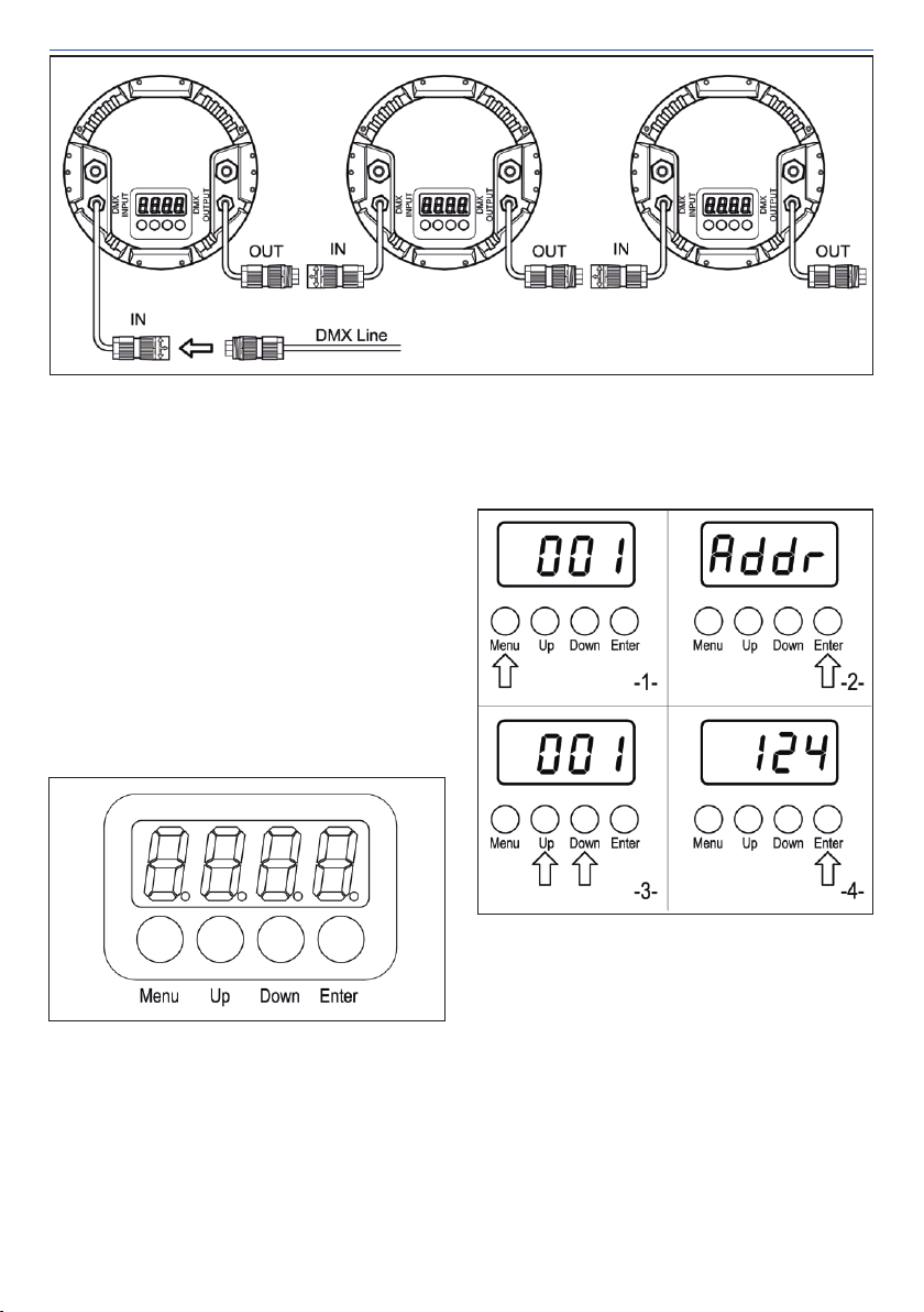
Afterpoweringupthefixture,thedisplayshows;
then, at the end of the electronic board reset
routine,theDMXaddressisdisplayed.Duringthe
resettheLEDsourceiskeptoff.
If there is no DMX signal, the address shown on
thedisplaystartsflashing.
Select the base address of the projector as seen
above and connect the signal coming from the
DMX control unit to control the various functions
oftheprojector.
To access the list of projector options press the
MENU button. The display shows the various
options starting from option 1, the base DMX
address. The active option from time to time
comes identified by the ignition of a point in the
middleoftheword.MovewithinthelistwithUPor
DOWN keys. Press ENTER to enter in the
submenu related to the desired option; here you
can choose other parameters of the projector or
you will simply be asked to enable or disable the
option. With the UP and DOWN keys you can
change the values, then press ENTER to confirm
the choice; to exit from menu items press the
MENU button until the display shows the DMX
baseaddress.
Option1DMXaddress
When the display shows Addr, press ENTER.
PresstheUPorDOWNbuttonsasmanytimesas
necessary required to view the desired channel
number. The address currently seton projector is
displayed without the dot to the right. To fast
forward,pressandholdthebutton.PressENTER
toconfirmthesetting.
Option2Manualcontrol
With this mode it is possible to manually set the
color of the light through the display interface,
thanks to the mixing of the five basic colors
available in the projector. Regardless of the
valuespresentonthebusDMX,withinthisoption
the projector reproduces the tone set via the
display. When the display shows L press
ENTER. The display shows the list of selectable
colors, press the UP or DOWN keys to scroll
throughthelist:
r,Redcolor U,Whitecolor
g,Greencolor A,Ambercolor
b,Bluecolor P,notused
PressENTERincorrespondencewiththedesired
color,thedisplayshowsthecurrentintensityvalue
stored for the chosen color, in DMX units (0 to
255). Press the UP or DOWN buttons as many
times as required to reach the desired intensity
level.Forfastforward,pressandholdthebutton.
PressENTERtostorethevalue,or press MENU
to exit without saving. Repeat these steps for all
othercolorsasneeded.
OncetheRGBWAcolortobeprojectedhasbeen
settherearetwopossibilities:
press MENU to return to DMX control and view
thelistofoptions;
switch off the projector without exiting the L
menu: the next time you switch it back on (it
doesn't matter if the DMX signal is connected or
not) the projector switches on the LED source at
thestoredcolor.
This function is useful for installations where the
luminairedoesnotneedtoberemotelycontrolled
andthelightcolormustremainfixed.
To reactivate the DMX control it is necessary to
press MENU to return to the list of options, then
press UP or DOWN until Addr is displayed and
finallypressENTERtoactivatetheDMXcontrol.
Option3Manualstrobe
WhenthedisplayshowsFLAS,pressENTER,the
strobe effect is activated and the flashing speed
value from 1 to 10 appears on the display; 1
correspondstotheminimumspeedand10tothe
maximumspeed.PresstheUPorDOWNbuttons
to select the desired speed. Press ENTER to
confirmthesetting.
To deactivate the strobe mode, press MENU to
returnto thelistof optionsandactivate anyother
menuitembypressingENTER.
Option4Crossfade
WhenthedisplayshowsFAd1pressENTER,the
crossfade effect is activated between the colors
red, yellow, green, cyan, blue, magenta and the
display shows the rotation speed value from 1 to
10;1 corresponds tothe minimum speed and 10
to the maximum speed. Press the UP or DOWN
buttonstoselectthedesiredspeed.PressENTER
toconfirmthesetting.
To deactivate the fade mode, press MENU to
returnto thelistof optionsandactivate anyother
menuitembypressingENTER.

8/12
AR3333RGBWA
Option5Coloredpulses
WhenthedisplayshowsFAd2,pressENTER,the
colored pulse effect is activated (ramp from 0 to
100%) on a series of preset tones and the value
of the execution speed from 1 to 10 appears on
thedisplay;1correspondstotheminimum speed
and 10 to the maximum speed. Press the UP or
DOWNbuttonstoselectthedesiredspeed.Press
ENTERtoconfirmthesetting.
To deactivate the pulse mode, press MENU to
returntothelistofoptionsandactivate any other
menuitembypressingENTER.
Option6Fixedcolorrotation
WhenthedisplayshowsASC pressENTER,the
continuous rotation effect is activated on a series
of preset tones and the value of the rotation
speed from 1 to 10 appears on the display; 1
correspondstothe minimumspeedand10 tothe
maximumspeed.PresstheUPorDOWNbuttons
to select the desired speed. Press ENTER to
confirmthesetting.
To deactivate the rotation mode, press MENU to
returntothelistofoptionsandactivate any other
menuitembypressingENTER.
Option7Configuringtheprojector
When the display shows CONF press ENTER.
The display will show a configuration submenu in
whichyoucanmovewiththeUPorDOWNkeys:
SIgN, the option is not active on this device.
However, forcorrectoperationit mustbesetto 1.
Press ENTER, move inside the new submenu
withtheUPorDOWNkeys:
1,pressENTERtoconfirm.
2,notactive.
NOS, this option allows you to determine the
behavior of the projector when the DMX signal is
disconnected. Press ENTER, move inside the
newsubmenuwiththeUPorDOWNkeys:
ON,pressENTERtokeeptheLEDsourceonin
theabsenceofDMXsignal.
OFF, press ENTER to turn off the LED source
whentheDMXsignalfails.
CHS,thisoptionallowsyoutosetthenumberof
DMX channels to be used for controlling the
projector, from 1 to 7. For a description of the
functions of the various channels, consult the
appropriate section of the manual. Press ENTER,
move inside the new submenu with the UP or
DOWNkeys:
CH1, press ENTER to activate the 1 channel
mode. The order of the channels in this mode is
thefollowing:
Thedimmerfunctionisactiveonlyonwhitecolor.
CH6, press ENTER to activate the 5 channels
mode. The order of the channels in this mode is
thefollowing:
CH7, press ENTER to activate 6 channels
mode. The order of the channels in this mode is
thefollowing:
CH8, press ENTER to activate 7 channels
mode. The order of the channels in this mode is
thefollowing:

9/12
USER'SMANUAL
dISP,thisoptionallowsyoutoestablishwhether
to turn off the display during normal operation.
Press ENTER, move inside the new submenu
withtheUPorDOWNkeys:
ON,pressENTERtokeepthedisplayalwayslit
ontheDMXaddress.
OFF, press ENTER to turn off the display when
the latter has not been used for more than 30
seconds. Press any button to reactivate the
display.
Option8C,notactiveonthismodel
Option9SoftwareVersion
When the display shows VEr press ENTER to
viewthesoftwareversioncurrentlyinstalledinthe
projector; press MENU to return to the list of
options.
DMXCHANNELFUNCTIONS
In the following diagrams you will find the control
valuesinDMXunits(0255)forallchannelsofthe
projector.
ChannelDimmer
The intensity of the light is linearly variable from
off to maximum; in particular, for the DMX value
equal to 0 the LED source is turned off, for
intermediate increasing values the brightness
gradually increases, for the value 255 the LED
sourceisturnedonatmaximumintensity.
ChannelStrobe
The projector is able to generate an electronic
strobe effect, obtained by quickly switching the
LED source on and off, whatever color is
reproduced. Strobe is disabled for DMX values
between0and5,whileforvaluesbetween6and
255 the frequency of the flashes gradually
increases.
ChannelRed
Theintensityoftheredsourceislinearlyvariable
from off to maximum; in particular, for the DMX
value equal to 0 the source is turned off, for
intermediate increasing values the brightness
gradually increases, for the value 255 the red
sourceisturnedonatmaximumintensity.

10/12
AR3333RGBWA
ChannelGreen
The intensity of the green source is linearly
variablefromofftomaximum;inparticular,forthe
DMXvalueequalto0thesourceisturnedoff,for
intermediate increasing values the brightness
gradually increases, for the value 255 the green
sourceisturnedonatmaximumintensity.
ChannelBlue
Theintensityofthebluesourceislinearlyvariable
from off to maximum; in particular, for the DMX
value equal to 0 the source is turned off, for
intermediate increasing values the brightness
gradually increases, for the value 255 the blue
sourceisturnedonatmaximumintensity.
ChannelWhite
The intensity of the white source is linearly
variablefromofftomaximum;inparticular,forthe
DMXvalueequalto0thesourceisturnedoff,for
intermediate increasing values the brightness
gradually increases, for the value 255 the white
sourceisturnedonatmaximumintensity.
ChannelAmber
The intensity of the amber source is linearly
variablefromofftomaximum;inparticular,forthe
DMXvalueequalto0thesourceisturnedoff,for
intermediate increasing values the brightness
gradually increases, for the value 255 the amber
sourceisturnedonatmaximumintensity.

11/12
USER'SMANUAL

12/12
AR3333RGBWA
WARRANTYCONDITIONS
The unit is guaranteed for 24 months from the
date of purchase against defects in workmanship
ormaterialsthatcomposeit.
This warranty does faults due to incorrect or
improperuseofthedevice.
The warranty is immediately void if the unit has
been tampered with or opened by unauthorized
personnel.
The warranty provides, at the discretion ofArena
Luci,repairorreplacementoffaultyequipment.
The serial number and model of the device are
required to obtain information or assistance from
the dealer. We invite you to transcribe them in
time: for any request of information or services,
thiswillresultinaquickandeffectiveoperation.
CERULES
The device meets the essential requirements of
the Directives LVD 2014/35/UE, EMC
2014/30/UE, RAEE 2012/19/UE, RoHS
2011/65/UE, Ecodesign 2009/125/CE reg. (UE)
1194/2012, Energy label 2010/30/UE reg. (UE)
874/2012 reg. (UE) 518/2014, GPSD
2001/95/CE.
Warnings
DisposalofOldElectrical&Electronic Equipment
(applicable in the European Union and other
European countries with separate collection
systems).
The product shall not be treated as
householdwastebutmustbehandedoverto
the applicable collection point for the
recycling of electrical and electronic
equipment. By ensuring this product is correctly
disposed, you will help prevent potential negative
consequences for the environment and human
health, which could otherwise be caused by
inappropriate waste handling. The recycling of
materialswillhelptoconservenaturalresources.For
more detailed information about recycling of this
product, please contact your city office, your
householdwastedisposalserviceoryoursupplier.
ArenaLucisrlviaSvizzera12/1446042CastelGoffredo(MN),Italy
Tel.+390376782411Fax+390376780973
www.arenaluci.com[email protected]
Powersupply
Powerconsumption
Source
Colour
Luminousflux
Beamaperture
Control
Connection
Material
Colour
Insulationclass
Weight
Dimensions
Protection
AmbientTemperature
Suitabletobefittedonnormallyinflammablesurfaces
Appliedstandards
100÷240VAC50Hz
140Wmax
9LEDsinglechip5in1
FullcolourRGBWA.CRI>80
7250lm(output)
35°
DMX512,7controlchannelswithdisplay
Powercablewithwaterproofconnector
Aluminiumandsteelplate
Epoxypowderpaintfinish,black
I
5kg
197x206x197mm(body)
IP65
From20°Cto+45°C
TECHNICALSPECIFICATION
AR3333RGBWAENR1|09/2020
Table of contents
Other Arena Luci Spotlight manuals
Popular Spotlight manuals by other brands

LIVARNO LUX
LIVARNO LUX LSL 10 A2 user manual

Desisti
Desisti REMBRANDT PICCOLO 575 w SE instruction manual

Delta Light
Delta Light M20-SPY 9-SOFT DIM5 installation instructions

PULSE+
PULSE+ PLS00571 quick start guide

LIVARNO LUX
LIVARNO LUX HG00108A, HG00108B Assembly, operating and safety instructions

Nite Ize
Nite Ize Inova LED Microlight quick start guide