Argal PDA 75 User manual

PDA
DEALER for Maintenance
date of commissioning:
.......................................................................................
position / system reference:
.......................................................................................
service:
.......................................................................................
USER MANUAL
Part number

2
TABLE OF CONTENTS
2 TABLE OF CONTENTS
3 IDENTIFICATION CODE
5 LEGEND
6 GENERAL NOTES
6 OPERATING PRINCIPLE
7 INSTALLATION AND USE INSTRUCTIONS
7 INSTALLATION
9 START UP
9 STOP
7 STORAGE INSTRUCTIONS
7 TRANSPORT
9 USE
10 MAINTENANCE
10 DISASSEMBLY
10 INSPECTION
11 SAFETY RULES
12 INSTALLATION AND START-UP PERSONNEL
12 MAINTENANCE AND OPERATIONAL PERSONNEL
13 PERSONNEL RESPONSIBLE FOR REPAIRS
13 WASTE DISPOSAL
13 TROUBLESHOOTING AND POSSIBLE CAUSES

3
year of manufacture
XXXX
PDA 100 WR M T 0 G
N01 ATEX
II 3 G c T4
s.r.l
CHEMICAL PUMPS
Ord. No
No
PNEUMATIC DAMPER
BRESCIA
ITALY
IDENTIFICATION CODE
PART NUMBER
MODEL
RANGE
Each damper is supplied with the serial and model abbreviation and the serial number on the rating plate, which is ri-
veted onto the support side. Check these data upon receiving the goods. Any discrepancy between the order and the
delivery must be communicated immediately.
In order to be able to trace data and information, the abbreviation, model and serial number of the pump must be quoted
in all correspondence.
Year of manufacture ____________________ Part number _____________________
II 2/2 GD c IIB T135°C II 3/3 GD c IIB T135°C
II 2/2GD: surface equipment for use in areas with the presence of
gases, vapors or mists in addition to clouds of combustible dust in
the air that occur occasionally during normal operation (EN 1127-
1 par. 6.3), both in external and internal areas (ZONE 1).
c: protection by constructional safety (EN 13463-5).
IIB: excluding the following products hydrogen, acetylene,
carbon disulphide.
T135°C: class of admitted temperatures. The processed uid
temperature value must fall within such class range and the user
must comply with the instructions contained in the manual and
with the current laws. Furthermore, the user must take into ac-
count the ignition point of the gases, vapors and mists in addition
to clouds of combustible powder in the air existing in the area of
use.
II 3/3GD: surface equipment used in areas where the presence of
gas, vapors or mists in addition to clouds of combustible powder
in the air is unlikely during normal operation both in external and
internal areas and, if it does occur, it will only persist for a short
period (ZONE 2).
c: protection by constructional safety (EN 13463-5).
IIB: excluding the following products hydrogen, acetylene,
carbon disulphide.
T135°C: class of admitted temperatures. The processed uid
temperature value must fall within such class range and the user
must comply with the instructions contained in the manual and
with the current laws. Furthermore, the user must take into ac-
count the ignition point of the gases, vapors and mists in addition
to clouds of combustible powder in the air existing in the area of
use.
range model materials connection
chambers ATEX diaphragm o-ring tipe
PDA
□ 75 (3/4”) □ WR GFR-PP □ X □ H keyex®□ N (NBR) □ G letto BSP
□ 100 (1”) □ FC CF+PVDF □ X □ M santoprene®□ V (FKM)
□ 150 (1 1/2”) □ DF PVDF □ D EPDM □ E (EPDM)
□ 200 (2”) □ AL alluminio □ X □ N NBR □ T (PTFE)
□ SS AISI 316 □ X □ U poliuretano □ 0 (no o-ring)
□ SP polished AISI 316 □ X
□ HT Keyex® + PTFE
□ MT santoprene®+ PTFE
□ T PTFE

4
4
3
6.a
6.b
5
7
7
2
1
4
3
2
12
6.b
1314
20
21
22
23
24
4
11
3
2
1
5
5
8
9
10
8
9
10
11
1
MODEL 75
MODEL 100-150
MODEL 200

5
LEGEND
note ref. pos. Description Q.ty Disassembling steps sequence
1234567891011 12
910.1 1 connections dampener casing 1 ●
102.1 2 Air side casing 1 ●
135.1 3 Wet side diaphragm 1 ●
102.2 4 Wet side casing 1 ●
412.1 5 O-ring 1 ●
412.2 6.a O-ring 1 ●
135.2 6.b Air side diaphragm 1 ●
514 7 Anello di battuta 1 ●
910.2 8 Cap connection 1 ●
488 9 Air side cap 1 ●
260.1 10 Wet side cap 1 ●
182 11 Base (optional for 150) 2 ●
412.3 12 O-ring 2 ●
13 Adaptor tting 2●
910.3 14 connection wet side casing / adaptor tting 2●
Pneumatic valve
675 20 Valve body 1 ●
412.4 21 O-ring 1 ●
412.5 22 O-ring 2 ●
210 23 Probe 1 ●
260.2 24 probe cap 1 ●

6
version
MAX Temperature (°C / °F) MAX Temperature (°C / °F)
Zone 1 (atex) Zone 2 (atex)
WR 60°C / 140°F 60°C /140°F
FC 80°C / 176°F 90°C / 194°F
DF NA 90°C / 194°F
SS 80°C / 176°F 95°C / 203°F
AL 80°C / 176°F 95°C / 203°F
SP 80°C / 176°F 95°C / 203°F
Version MAX ΔT (°C / °F)
WR 0÷40°C / 14÷104°F
FC 0÷40°C / 14÷104°F
DF 0÷40°C / 14÷104°F
SS 0÷40°C / 14÷104°F
AL 0÷40°C / 14÷104°F
SP 0÷40°C / 14÷104°F
GENERAL NOTES
The”PDA” dampeners are accessories for the AODD pump and have used for dampen the variations in ow and pres-
sure in the AODD pump discharge.
The dampener performances (ow rate, head, and minimum pressure) are decided in the ordering phase and indicated
on the nameplate
Make sure that the physical-chemical characteristics of the uid have been correctly evaluated
The maximum temperature referred to water in continuous operation depends on the version of the materials (indicated
on the nameplate) and on the environment in which the pump will be installed:
The ambient temperature interval is related to the choice of materials (specied on the identication plate):
OPERATING PRINCIPLE
The damper consists of two chambers separated by diaphragm. A chamber is connected to the pump outlet and the
second is charged or discharged of air.
The pressure that the pumped liquid exerts on the wet side of thediaphragm deforms the same. This deformation moves
a probe that control the pneumatic valve that charging or discharging air as a function of the position assumed by the
probe. The head frequency and capacity are automatically adjusted without any intervention or set up according to the
actual product circuit requirements

7
INSTALLATION AND USE INSTRUCTIONS
TRANSPORT
cover the hydraulic connections•
lift the hydraulic plastic parts without mechanical stress•
for transport on irregular roads, cushion the bumps with suitable support plane•
blows and impacts may damage parts that are important for the machine operation and safety•
STORAGE INSTRUCTIONS
When is necessari to store the dampeners before installation don’t remove it from the original packaged. The packa-•
ged dampeners must be stored lifted from ground level, the ambient must be close, clean and dry.
If at the receipt of the dampeners package seems damaged is necessary to free the dumpner in order to check its•
integry and to store a new package
The place where the dampeners is stored must be closed with an ambient temperature not lower than –5°C and•
not higher than 40°C, the air humidity rate not higher than 80%, the package dampeners mustn’t received shock,
vibrations and loads rising above.
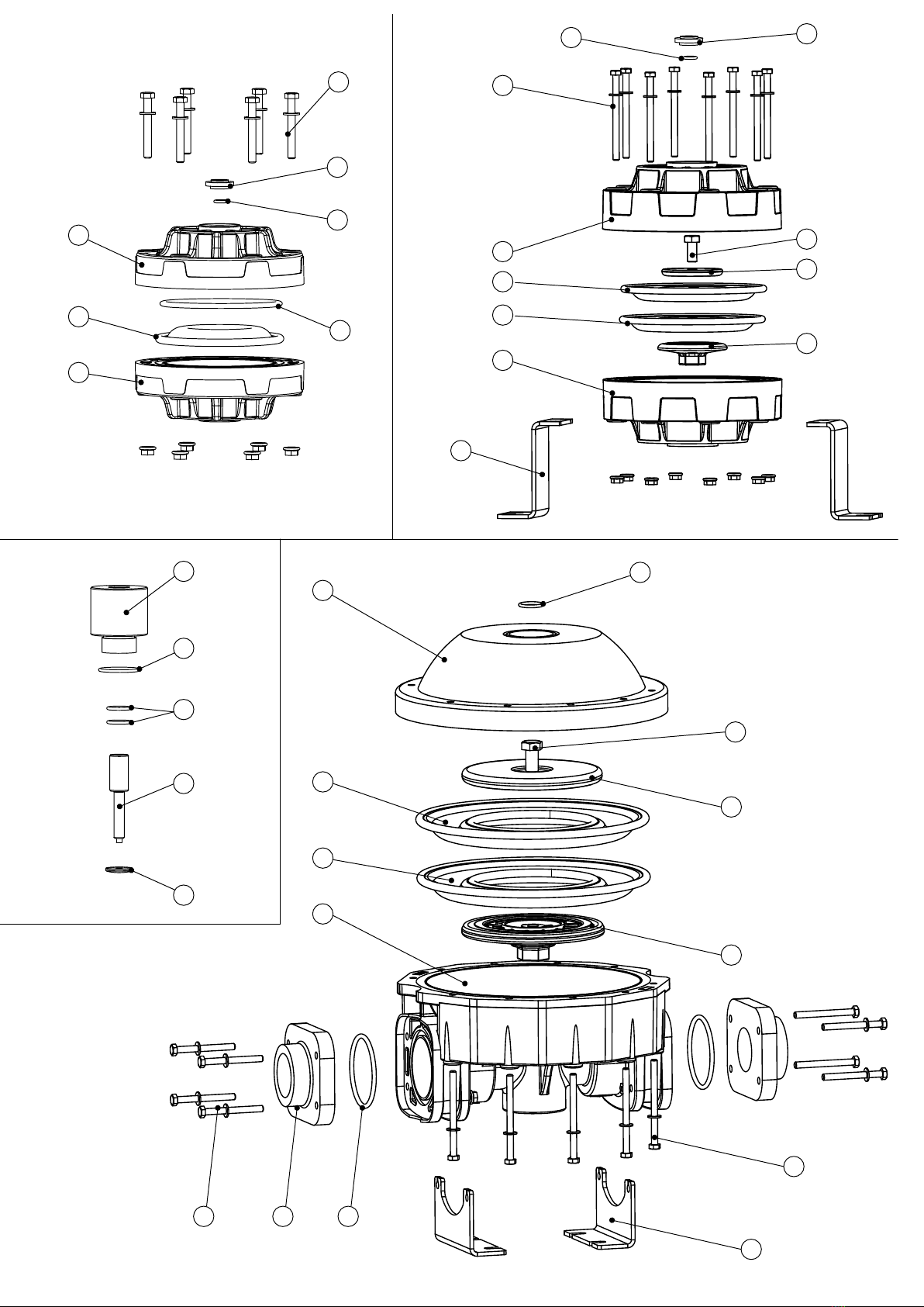
INSTALLATION
clean the plant before connecting the pump and dampener•
make sure that no foreign bodies are left in the dampener. Remove safety caps on the hydraulic connections.•
make sure that all of the dampener’s screws are well tightened•
position and secure the dampener horizontally•
place the pump and the dampener nearest at the suction point•
only ttings with cylindrical gas threads in materials compatible with both the uid to be pumped and the dampener’s •
construction materials must be used for the connections to the dampener’s collectors
pneumatic supply to the dampener must be made using ltered, died and not lubricated oil free at a pressure of not •
less than 2 bars and not more than 7 bars.
can use the same pneumatic supply of the pump•
follow the instructions indicated in the following diagram:
1. YES: use exible pipes reinforced with rigid spiral to connect the hydraulic circuit of the pump. Rigid piping may cau-
se strong vibrations and manifolds breaking. Do not use pipes with nominal diameter smaller than the diameter of the
pump connections. For negative installations and/or viscous uids use pipes with greater diameter related to the nominal
diameter of the pump
2. YES: install and connect the pipe downstream from the pulsation dampener. Its diameter must never be smaller than
the connection. The pipe downstream from the dampener can be rigid and made from material compatible with the uid
to be pumped
3. YES: pipe for safety discharge; if the diaphragms are completely torn, the uid may enter the air circuit damage it,
and be discharged through the exhaust port. It is therefore necessary that the air exhaust be conveyed by pipes into a
piping reaching a safe area
4. YES: pipe anchoring; the piping must be sufciently strong to avoid deformation and must never weigh down on the
dampener in any way or viceversa
5. YES: shut-off valve of the same diameter as the pump inlet (never smaller) to intercept the uid correctly in case of
spills and/or when servicing the pump
6. YES: horizzontal place
7. NO: vertical place
8. YES: carry out effective grounding using a suitable size of cable on each pump casing to discharge static currents
9. YES: dampener anchoring
10.YES: trap
11.YES: pressure regulator with gauge
12.YES: check valves on the air supply piping to prevent the pumped liquid from entering the pneumatic circuit if the
diaphragms are broken is forbidden
13.YES: three-way valve for stop the dampener
14.YES: ow regulator
ensure drainage of uids which may come out of the dampener•
x the dampener avoid that the pipe weight down up it•
arrange for enough room around the dampener for the movements of an operator•
inform about the presence of aggressive uid with suitable coloured labels in accordance with the related standard•

8
1
5
10
11
12
13
14
4
2
3
7
9
6
8
hydraulic connections
pneumatic connections
do not install the dampener (built with thermoplastic material) near heat sources•
do not install the dampener in places with risk of fall of solids or uids•
do not install the dampener close to xed workplaces or visited areas•
install additional protection shield, for the pump or for the persons as appropriate. If the diaphragm breaks the uid •
may enter into the pneumatic circuit and come out from the pump discharge port
if the dampener is made from conductive materials and is suitable for ammable products, each casing must be •
equipped with a suitable earthing cable: DANGER OF EXPLOSION AND/OR FIRE
WARNING:The dampener must always be grounded irrespective of any organ to which they are connected.Lack•
of grounding or incorrect grounding will cancel the requirements for safety and protection against the risk of explo-
sion
For installation and use in a potentially explosive enviroment, comply with these general precautions:
ascertain that the dampener is full•

9
ascertain that the uid treated does not contain or cannot contain large solids or solids for a dangerous shape•
ensure that the intake or delivery ports are not obstructed•
also ascertain that the connection piping is strong enough and cannot be deformed by the dampener’s weight or by•
the intake. Also check that the dampener is not burdened by the weight of the piping
if the dampener is to stay in disuse for a long period of time, clean it carefully by running a non-ammable liquid •
detergentthrough it that is compatible with the dampener’s construction materials
if the dampener was turned off for a long period of time, circulate clean water in it for some minutes to avoid incru-•
stations
WARNING:The use of dampeners for ammable liquids•
is forbidden if they are made of non-conductive•
materials that charge statically (plastic materials) and without suitable grounding DANGER OF EXPLOSION CAU-•
SED BY STATIC CHARGES
START UP
check the correct execution of what indicated in the INSTALLATION paragraph•
check that the intake and delivery pipes of the hydraulic circuit are correctly connected•
open the intake and delivery valves of the pump hydraulic circuit•
open the 3-way valve on the air circuit•
set the operation point requested for the pump: properly adjust the air pressure and delivery that supplies the pump.•
With pressure values under 2 bar the pump may stall, with pressure values above 7 bar it is possible that brea-
kdowns and/or yields may occur with consequent spillage of the pumped uid
for pumps with split manifold the two pumped uids must have the same viscosity value, very different viscosity •
values may lead to stall problems and/or diaphragms breaking
do not operate at the limits of the operation curves: the maximum head or maximum delivery (total absence of leaks•
and intake height in the delivery circuit)
check that there are no anomalous vibrations or noise due to the too elastic support structure, unsuitable fastening•
or cavitation
after 2 hours of operation stop the pump correctly and check the tightening of all the bolts on the dampener•
WARNING: never start the dampener with the product valves closed: danger of diaphragm breakage
STOP
To stop the pump and dampener, operate exclusively on the air supply closing the 3-way valve, discharging in this•
way residual pressure from the pneumatic system of the pump.
WARNING never stop the pump and dampener by totally closing the suction and/or delivery valves of the hydraulic
circuit
USE
do not operate valves or shunts during the pump operation•
risk of harmful water hammers in case of incorrect or sudden operations (valves must be operated only by trained•
personnel)
empty and wash accurately inside the dampener in case different uids must be pumped•
insulate or empty the dampener if the uid crystallization temperature is equal to or below the ambient temperatu-•
re
stop the pump if the uid temperature exceeds the maximum allowed temperature indicated in the GENERAL NO-•
TES; if the exceeding temperature is about 20% it is necessary to inspect the status of the internal parts
stop the pump and close the valves in case of leaks•
wash with water only if chemical compatibility allows it ; alternatively use the suitable solvent that does not generate•
hazardous exothermic reactions
consult the uid supplier to decide the most suitable re-prevention method•
empty the dampener in case of long periods of disuse (particularly with uids which are particularly tending to cry-•
stallize)
check that there is no gas in the delivering uid, if there is stop the pump•
WARNING: never stop the dampener and the pump when it is running and/or when the pneumatic circuit is under pres-
sure by closing the intake and/or delivery valves on the uid circuit: danger of premature wear and/or breakage of the
diaphragm

10
MAINTENANCE
all the operation must be carried out by qualied personnel•
do not carryout maintenance and/or repairs with the air circuit under pressure; only the air supply must be used to•
stop the dampener by closing the three-way valve to discharge any residual pressure from the dampener’s pneu-
matic circuit
discharge the product being pumped and close the product onoff valves•
carry out periodic inspections (2 ÷ 30 days in accordance with the uid pumped) to check the ltering elements •
cleaning
carry out periodic inspections (3 ÷ 5 months in accordance with the uid pumped and with the environment condi-•
tions) to ensure the correct operation of the system start/stop units
he presence of uid under the dampener casing may indicate failures to the dampener•
damaged parts must be replaced with complete original parts and not with repaired parts•
the replacement of damaged parts must be carried out in a clean and dry place•
remove the powder deposits from the external surfaces of the pulsation dampener with a cloth soaked in suitable•
neutral detergents
periodically control and clean the internal surfaces with a damp cloth•
RECOMMENDATIONS
WARNING: before performing any maintenance or repair work on the pump and dampener, disconnect the pump from
the air supply line. Disconnect the hydraulic connections and discharge the product that is being pumped
all the operation must be carried out by qualied personnel
use gloves, goggles and acid-resistant clothing when disconnecting from the system and washing the dampener
wash the dampener before carrying out maintenance operations
do not disperse the washing waste into the environment
DISASSEMBLY
Bolts are the type with right thread
Clean all the dampner external surfaces using a damp cloth
DIAPHRAGMS REMOVAL
separate the dampener’s casing removing the xed screws
clean all the dampner surfaces using a damp cloth
remove the cap (if present)
PNEUMATIC VALVE REMOVE
unscrew the valve from the casing
WARNING: to avoid incorrect reassembly and subsequent malfunction of the dampener the automatic valve must not
be open
INSPECTION
Check the absence of:
excessive abrasion of the thermoplastic parts•
clots and/or agglomerates due to the pumped uid•
deformations and/or surface lesions of the diaphragms•
deformations and/or surface lesions of the dampener casing•
replace the parts: broken, cracked, deformed•
reopen all the clogged ducts and eliminate any chemical agglomerates•
Clean all the surfaces before reassembly, particularly the OR gaskets seats (risk of leaks for dripping)•
WARNING: Should the dampener be returned to the manufacturer or service center, you must empty it out comple-•
tely. In toxic, noxious or other types of dangerous products have been used, the dampener must be suitably treated
and washed before it is sent
CLEANING AND REPLACING THE DIAPHRAGMS
control and internal cleaning every 500.000 cycles
diaphragm check every 5.000.000 cycles
diaphragm replacement every 20.000.000 cycles

11
SAFETY RULES
WARNING! CHEMICAL RISK. Pumps are intended for operation with different types of uids and chemical solutions.
Follow the specic internal instructions for decontamination during the inspection or maintenance operations.
WARNING: the diaphragms (into contact with the product and external) are components extremely subject to wear.
Their duration is strongly affected by the conditions of employments and by chemical and physical stresses. By tests
carried out on thousands of pumps installed with head value from 0° to 18°C, the ordinary life exceeds one hundred
million cycles. For safety reasons, in environments with explosion risk it is necessary to disassemble and check the
diaphragms every ve million cycles and to replace them every twenty million cycles.
WARNING! In the case of diaphragms total breaking, the uid may enter in the pneumatic circuit, da-
mage it and come out from the discharge port. Therefore it is necessary to convey the air discharge in
a piping up to a safe area.
WARNING! In situations where the user foresees the possibility of exceeding the temperature limits
indicated in this manual, it is necessary to install a protection device on the equipment that prevents
to achieve the maximum operating temperature allowed. If exceeded, respect to the maximum marking
temperature is not guaranteed.
REMEMBER! Safety risks to persons are mainly caused by improper use or accidental damage.These
risks may be of hand injury for operators working on the open pump, or caused by the nature of the uids
that are conveyed by this type of pump. Therefore it is extremely important to diligently carry out all the
instructions contained in this manual in order to eliminate the causes of accidents that may lead to the
pump failure and to the subsequent outcome of uid hazardous to persons and to the environment.
For installation and use in a potentially explosive environment, comply with these general precautions:
ascertain that the dampener is full and if possible, that the level is above it by 0.5 m
ascertain that the uid treated does not contain or cannot contain large solids or solids of a dangerous shape
also ascertain that the connection piping is strong enough and cannot be deformed by the dampener’s weight or by the
intake. Also check that the dampener is not burdened by the weight of the piping
if the dampener is to stay in disuse for a long period of time, clean it carefully by running a non-ammable liquid deter-
gent through it that is compatible with the dampener’s construction materials;
if the dampener was turned off for a long period of time, circulate clean water in it for some minutes to avoid incrusta-
tions
before starting, after long periods of disuse, clean the internal and external surfaces with a damp cloth
check the grounding
always protect the dampener against possible collisions caused by moving means or by various blunt materials that may
damage it or react with its materials;
protect the dampener’s surrounding ambient from splashes caused by accidental dampener failure
WARNING: the air supply pressure must never be over 7 bar or below 2 bar
WARNING: when using the pump with aggressive or toxic liquids or with liquids that may represent a health hazard you
must install suitable protection to contain, collect and signal any spills: danger of pollution, contamination, injuries and/
or death
WARNING: the dampener cannot be used with uids that are not compatible with its construction materials or in a place
containing incompatible uids.
WARNING: installing the dampeners without on-off valves on the intake and delivery sides to intercept the product in
case of spillage is forbidden: danger of uncontrolled product spillage.
WARNING: installing the dampeners without on-off, three-way or check valves on the air supply piping to prevent the
pumped liquid from entering the pneumatic circuit if the diaphragms are broken is forbidden: danger of uid entering the
compressed air circuit and being discharged into the environment
WARNING: should the user think that the temperature limits set forth in this manual may be exceeded during service, a
protective device must be installed on the system that prevents the maximum allowed process temperature from being
reached. If exceeded, respect of the maximum temperature displayed on the marking is not guaranteed
WARNING: the dampener must always be grounded irrespective of any organ to which they are connected. Lack of
grounding or incorrect grounding will cancel the requirements for safety and protection against the risk of explosion

12
WARNING: the use of dampeners for ammable liquids is forbidden if they are made of non-conductive materials that
charge statically (plastic materials) and without suitable grounding danger of explosion caused by static charges
WARNING: Aggressive, toxic or dangerous liquids may cause serious injuries or damage health, therefore it is forbidden
to return a dampener containing such products to the manufacturer or to a service center. You must empty the internal
circuits from the product rst and wash and treat it
WARNING: dampeners containing aluminium parts or components coming into contact with the product cannot be used
to pump iii-trichloroethane, methylene chloride or solvents based on other halogenated hydrocarbons: danger of explo-
sion caused by a chemical reaction
WARNING: the PDA dampeners cannot use with Acetylene, Hydrogen, Carbon disulde
WARNING: the components of the pneumatic exchanger, including the shaft are made from materials that are not spe-
cically resistant to chemical products. In case the diaphragm break, replace these elements completely if they have
come into contact with the product
WARNING: avoid using lubricated and/or un-dried air
WARNING: ascertain that no anomalous noises can be heard during operation. If they occur, stop the dampener imme-
diately
WARNING: ascertain that the uid at the delivery side does not contain gas. Otherwise stop the dampener immediate-
ly
WARNING: periodic controls must be made to ensure that there is no powder and/or deposits on the external and inter-
nal surfaces of the dampener and, if necessary, clean them with a damp cloth
WARNING: removal of the air supply pipe must be done when free from powder. Before restarting the dampener, ensure
that no powder has entered the pneumatic distributor
To replace worn parts, use only original spare parts
However ve general elements are important:
A- all the operations must be carried out by skilled personnel or monitored by qualied personal as appropriate
B- implement personal protection works (when the dampener is installed in places involving more than occasional visits)
against splashes of uorescent uid for accidental breakage and conveying works (always) of possible uid leakages
towards collection tanks
C- wear acid-resistant clothing and protection whenever operating on the pump
D- make sure that the Intake and delivery valves are correctly closed during the disassembly
E- make sure that there is no supply to the pneumatic circuit during the disassembly
It should be noted that it is very important to realize systems with pipes well arranged, identiable, suitably equipped
,with shut-off valves, with comfortable compartments and passages for operators who must inspect their status (since
the pressure developed by the pump may promote failures to the system if it is of defective construction or worn).
INSTALLATION AND START-UP PERSONNEL
Interventions allowed only to specialised personnel who may eventually delegate to others some operations depending
on specic evaluations (technical capability required: specialisation in industrial plumbing or electric systems as nee-
ded).
MAINTENANCE AND OPERATIONAL PERSONNEL
Interventions allowed to general operators (after training on the correct use of the plant):
dampener starting and stopping•
opening and closing of valves with the pump at rest•
emptying and washing of the pump body via special valves and piping•
cleaning of ltering elements•
Interventions allowed to qualied personnel (technical capacities required: general knowledge of the mechanical, elec-

13
WASTE DISPOSAL
Materials: separate plastic from metal parts. Dispose of by authorized companies.
DEFECT CAUSE SUGGESTION
1
The dampener
doesn’t run and/or
it doesn’t start
No air in the circuit Check circuit, valves and connections
Insufcient air pressure Adjust pressure on the relevant reducer
Insufcient air ow rate Check that piping and accessories have suitable passage
Damaged control valve Check and replace
Broken diaphragm Check if any air comes out from the product delivery pipe.
If so, replace diaphragm.
2
The dampener is
not performing at
its best
There is an air leak in the valve. Replace the air valve
The product pipe is clogged and ob-
structed Disassemble the product pipe and clean it
The product being pumped is too
viscous
The air is dirty, full of condensate or oil Check the air feed line.
Air volume or pressure is insufcient Ensure that all the air control equipment has sufcient ow
TROUBLESHOOTING AND POSSIBLE CAUSES
trical and chemical features of the plant being fed by the pump and of the pump itself):
verication of environmental conditions•
verication of the condition of the liquid being pumped•
inspections of the control/stop devices of the pump•
inspections of the rotating parts of the dampener•
trouble shooting•
PERSONNEL RESPONSIBLE FOR REPAIRS
Interventions allowed to general operators under the supervision of qualied personnel:
stopping of the dampener•
closing of the valve•
emptying of pump body•
disconnection of piping from ttings•
removal of anchoring bolts•
washing with water or suitable solvent as needed•
Interventions by qualied personnel (technical capacities required: general knowledge of machining operations, awa-
reness of possible damage to parts due to abrasion or shocks during handling, know-how of required bolt and screw
tightening required on different materials such as plastics and metals, use of precision measuring instruments):
opening and closing of the dampener body
removal and replacement of rotating parts

14
ØA
D
D
K
E
E
ØA
In
In
In
In
G
B
B
C
C
F
F
H
H
ØA
air inlet
air inlet
air inlet
discharge
discharge
discharge
75 - 100
150
200
TECHNICAL DATA
DIMENSIONS

15
model In air inlet discharge ØA B C D E F G H K
75 3/4” 3/8” 1/4” 120 125 / / / / / / /
100 1” 1/2” 1/4” 182 175 / / / / / / /
150 1 1/2” 3/8” 1/4” 231 252 100 328 298 60 / 345 /
200
(WR-FC-AL) 2” 1/2” 1/2” 350 / 140 224 153 80 108 405 395
200 (SS) 2” 1/2” 1/2” 350 / 114 314 254 80 100 395 390

°C
m
%
m3/h
w.o.
The INSTRUCTION MANUAL must be delivered to the pump-user , who
takes diligent note of it, lls in data for Maintenance Department (page
1), keeps the le for subsequent reference.Possible modications do not
imply updating of the existing manuals
© Copyright 2012 - ARGAL srl
Draw and text total or partial duplication is
prohibited
MANUFACTURER DATA
Production head and legal ofce:
Via Labirinto, 159 I - 25125 BRESCIA
Tel: 030 3507011 Fax: 030 3507077
Administration: Tel: 030 3507019
Export manager: Tel: 030 3507022
Customer service: Tel: 030 3507025
Web: www.argal.it
E-mail: [email protected]
CONTRACTUAL DATA
medium
conc.
capacity
temperature
head
REV.1 - 02/13
This manual suits for next models
3
Table of contents
Popular Industrial Equipment manuals by other brands

Eaton
Eaton NZM4-4-XKM1 Instruction leaflet

Beko
Beko BEKOMAT 31U F Instructions for installation and operation

Powermatic
Powermatic 72A Instruction manual & parts list

oventrop
oventrop Toc-Uno-N technical information

Doosan
Doosan G20 SIIIA Operation & maintenance manual

Electrothermal
Electrothermal MH8517 Instruction book