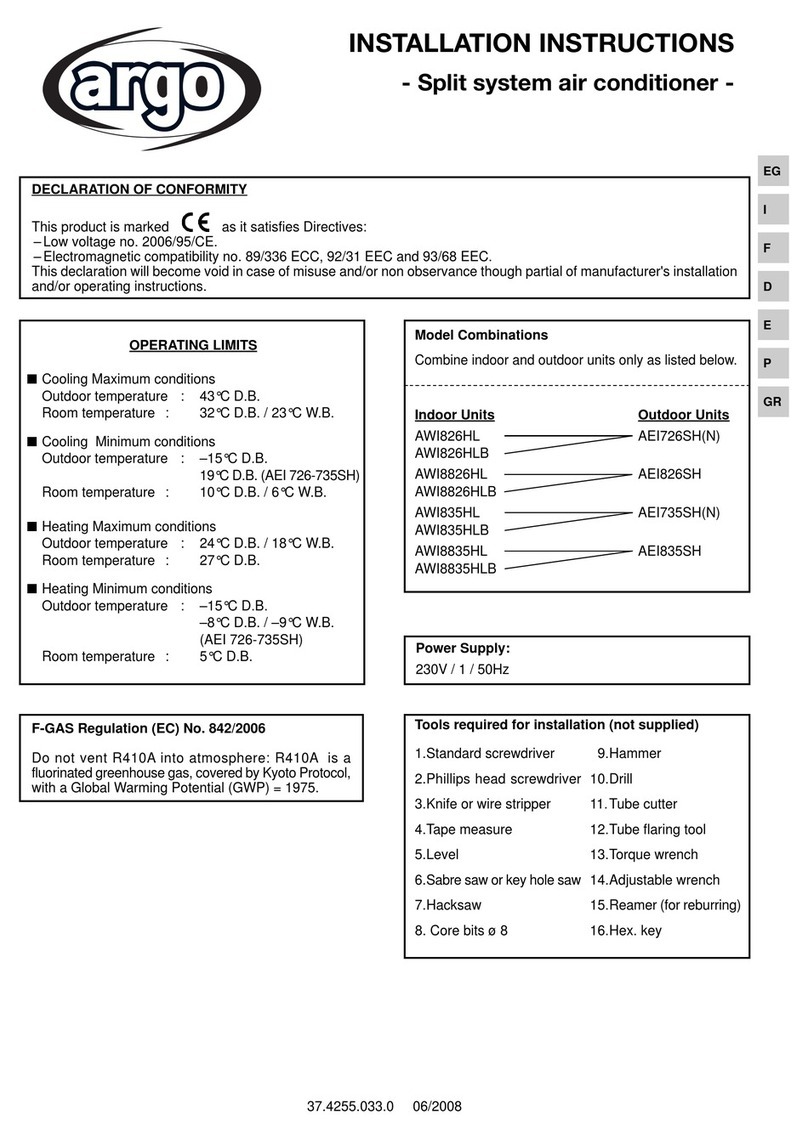
Argo AWIAS19 User manual

37.4255.224.00 01/2023
AWIAS19
AWIBS19
AWICS19
EN
IT
FR
INSTALLATION
INSTRUCTIONS
MANUALE
D’INSTALLAZIONE
NOTICE
D’INSTALLATION
INSTALLATIONS-
ANLEITUNGEN
INSTRUCCIONES
DE INSTALACIÓN
INSTRUÇÕES DE
INSTALAÇÃO
Split air conditioner system
Condizionatore d’aria split system
Climatiseurs split
Zweirohrsystem-Klimaanlage
Acondicionador de aire Split System
Sistema de ar condicionado de Unidades Separadas
DE
ES
PT

EN
2
IMPORTANT!
Please read before installation
This air conditioning system meets strict safety and operating standards.
For the installer or service person, it is important to install or service the system so that it operates safely and efficiently.
operation, you must:
• Carefully read this instruction booklet before beginning.
• Follow each installation or repair step exactly as shown.
• Observe all local, state and national electrical codes.
• Pay close attention to all warning and caution notices given in this manual.
•The unit must be supplied with a dedicated electrical line.
This symbol refers to a hazard or unsafe practice which can result in severe personal injury or death.
This symbol refers to a hazard or unsafe practice which can result in personal injury or product or property damage.
Recommendations
• The personnel responsible for receiving the unit must conduct a visual inspection in order to identify all damage to
which the unit may have been subjected during transport: refrigerating circuit, electrical cabinet, chassis and cabinet.
If necessary, get help
These instructions are all you need for most installation sites and maintenance conditions.
If you require help for a special problem, contact our sale/service outlet or your certified dealer for additional instructions.
In case of improper installation
The manufacturer shall in no way be responsible for improper installation or maintenance service, including failure to
follow the instructions in this document.
SPECIAL PRECAUTIONS
• During installation, connect before the refrigerant system and then the wiring one; proceed in the reverse orden when
removing the units.
WARNING
CAUTION
CONTENTS
1 - Installation site selection.................................................................4
2 - System wiring diagram ...................................................................4
3 - Wires’ length, size and delayed fuse............................................4
4 - Additional material required for installation (not supplied).............5
5 - Operating limits...............................................................................5
6 - Dimensions, weight and refrigerant connections ...........................5
7 - Accessories.....................................................................................5
8 - Tools required for installation (not supplied) ..................................5
9 - Installation procedure .....................................................................6
10 - Remote control unit installation......................................................9
11 - Wired controller installation (if present) ........................................10
12 - Pump Down ..................................................................................11
13 - Outdoor/indoor unit refrigerant circuit address............................12
14 - Match between remote controller and indoor unit.......................14
15 - Home Automation kit....................................................................15
16 - Jumper..........................................................................................15
17 - Parameters table...........................................................................16
18 - Electrical wiring diagram...............................................................17
EN
3
REGULATION (EU) No. 517/2014 - F-GAS
The unit contains R410A, a fluorinated greenhouse gas with a global warming potential (GWP) of 2087.50. Do not
release R410A into the atmosphere.
Model Combinations:
SEE
CATALOGUE
Power Supply:
220 - 240 V ~ 50 Hz
When wiring
ELECTRICAL SHOCK CAN CAUSE SEVERE PERSONAL INJURY OR DEATH. ONLY A QUALIFIED, EXPERIENCED
ELECTRICIANS SHOULD ATTEMPT TO WIRE THIS SYSTEM.
• Do not supply power to the unit until all wiring and tubing are completed or reconnected and checked, to ensure the
grounding.
• Highly dangerous electrical voltages are used in this system. Carefully refer to the wiring diagram and these instructions
when wiring.
Improper connections and inadequate grounding can cause accidental injury and death.
• Ground the unit following local electrical codes.
• The Yellow/Green wire cannot be used for any connection different from the ground connection.
• Connect all wiring tightly. Loose wiring may cause overheating at connection points and a possible fire hazard.
• Do not allow wiring to touch the refrigerant tubing or any moving parts of the fan
• Do not use multi-core cable when wiring the power supply and control lines. Use separate cables for each type of line.
When transporting
Be careful when picking up and moving the indoor and outdoor units. Get a partner to help, and bend your knees when
lifting to reduce strain on your back. Sharp edges or thin aluminium fins on the air conditioner can cut your fingers.
When installing...
... At the wall
Make sure the wall is strong enough to hold the unit-weight. It may be necessary to build a strong wooden or metal
frame to provide added supporte.
... In a room
Properly insulate any tubing run inside a room to prevent “sweating”, which can cause dripping and water damage to
walls and floors.
When connecting refrigerant tubing
• Keep all tubing runs as short as possible.
• Use the flare method for connecting tubing.
• Apply refrigerant lubricant to the matching surfaces of the flare and union tubes before connecting them; screw by
hand and then tighten the nut with a torque wrench for a leak-free connection.
• Check carefully for leaks before starting the test run.
NOTE:
Depending on the system type, liquid and gas lines may be either narrow or wide. Therefore, to avoid confusion, the
refrigerant tubing for your particular model is specified as narrow tube for liquid, wide tube for gas.
When servicing
• Turn the power OFF at the main power board before opening the unit to check or repair electrical parts and wiring.
• Keep your fingers and clothing away from any moving parts.
• Clean up the site after the work, remembering to check that no metal scraps or bits of wiring have been left inside the
unit being serviced.
• Ventilate the room during the installation or testing the refrigeration system; make sure that, after the installation, no
gas leaks are present, because this could produce toxic gas and dangerous if in contact with flames or heat-sources.
WARNING

EN
4
2 - SYSTEM WIRING DIAGRAM
DILAYED FUSE
220 - 240 V ~ 50 Hz
Main switch for disconnection from the
supply line must have a contact separation
in all poles that provides full disconnection
under category III overvoltage conditions.
3 - WIRES’ LENGTH, SIZE AND DELAYED FUSE
SEE INSTALLATION INSTRUCTIONS OF OUTDOOR UNIT
Power supply wire A :
Multipolar electric wire; size and length of the suggested electric wire are showed on table “electrical data”
(Outdoor unit).
Connecting wire B (SHIELDED):
Bipolar electric shielded wire; size and length of the suggested electric wire are showed on table “electrical data”
(Outdoor unit). The wires have not to be lighter than Mod. H05VVC4V5-K (according to CEI 20-20 CENELEC HD21).
Connecting wire C (with ground conductor):
Multipolar electric wire; size and length of the suggested electric wire are showed on table “electrical data”
(Outdoor unit). The wires have not to be lighter than Mod. H07RN-F (according to CEI 20-19 CENELEC HD22). Make
sure the length of the conductors between the fixing point and the terminals allows the straining of the conductors
L, N before that of the grounding.
1 - INSTALLATION SITE SELECTION
DO
• Select an appropriate position from which every corner
of the room can be uniformily cooled.
• Select a sufficiently strong location to support the weight
of the unit.
• Select a location where tubing and drain hose have the
shortest run to the outside.
• Allow access for operation and maintenance as well as
unrestricted air flow around the unit.
AVOID
• Direct sunlight.
• Nearby heat sources that may affect unit performance.
• Areas where leakage of flammable gas may be expected.
• Locations where large amounts of oil mist may occur
(such as in kitchen or near factory equipment) because
oil contamination can cause operation problems and may
deform plastic surfaces and parts of the unit.
• Unsteady locations that will cause noise or possible
water leakage.
• Locations where the indoor unit and the remote control
unit will be splashed with water or affected by dampness
or humidity.
• To make holes in areas where electrical wiring or conduits
are located
WARNING !
Always connect Phase to L and Neutral to N
DO NOT INVERT THE WIRES, OTHERWISE
THE UNIT MAY NOT WORK PROPERLY.

EN
5
4 - ADDITIONAL MATERIAL REQUIRED FOR INSTALLATION (NOT SUPPLIED)
5 - OPERATING LIMITS
6 - DIMENSIONS, WEIGHT AND REFRIGERANT CONNECTIONS
7 - ACCESSORIES
The following accessories are supplied with the unit:
• Remote control unit.
• Batteries for remote control unit.
• Swivel nuts for pipe connection.
• Insulating tube for piping exiting the unit.
• 4 jumper for PCB configuration (see section “JUMPER”)
• Wires for Home automation / wired controller (see section “HOME AUTOMATION KIT”):
- wire “Input Contact” - ON/OFF
- wire “Output Contact” - ALARM
Wired controller (optional - not supplied)
The wired controller (code 387030220) can be purchased separately and can be used to manage the single unit, but
also as a centralized controller.
ATTENTION! If you connect the wired controller, the receiver located inside the unit will be disabled and the wired
controller receiver will be activated, so it will be the latter to communicate with the infrared remote control if necessary.
8 - TOOLS REQUIRED FOR INSTALLATION (NOT SUPPLIED)
1.Standard screwdriver
2.Phillips head screwdriver
3.Knife or wire stripper
4.Tape measure
5.Level
6.Sabre saw or key hole saw
7.Hacksaw
8.Core bits ø 8
9.Hammer
10.Drill
11.Tube cutter
12.Tube flaring tool
13.Torque wrench
14.Adjustable wrench
15.Reamer (for reburring)
16.Hex. key
●Deoxidized annealed copper tube for refrigerant tubing connecting the units of the system; it has to be insulated with
foamed polyethylene (min. thickness 8mm). For tubing dimensions, tubing length and elevation difference limits, see
installation manual of outdoor unit.
●PVC pipe for condensate drain pipe (ø int.18mm) in lenght suitable to let the condensate flow into the outside drainage.
●Anti-freeze oil for flare connections (about 30g).
●Electric wire: use insulated copper wires of size and length as shown in the paragraph “WIRING DIAGRAMS” (Outdoor
unit).
■Cooling Maximum conditions
Outdoor temperature : 43°C D.B.
Room temperature : 32°C D.B. / 23°C W.B.
■Cooling Minimum conditions
Outdoor temperature : –15°C D.B.
Room temperature : 10°C D.B. / 6°C W.B.
■Heating Maximum conditions
Outdoor temperature : 24°C D.B. / 18°C W.B.
Room temperature : 27°C D.B.
■Heating Minimum conditions
Outdoor temperature : –15°C D.B.
Room temperature : 5°C D.B.
A
C
B
MODEL A (mm) B (mm) C (mm) CONNECTIONS
AWIA 889 294 212 1/4” - 3/8”
AWIB 1013 307 221 1/4” - 1/2”
AWIC 1122 329 247 3/8” - 5/8”
MODEL WEIGHT (kg)
AWIA 11
AWIB 13.5
AWIC 17.5

EN
6
9 - INSTALLATION PROCEDURE
AMinimum operation and maintenance area. BRemove and discard the set screw on the rear panel.
CPress on the hooks located below the 2 triangle
marks on the frame cover and disengage the frame. D
E
The unit can be connected to four directions: right
rear - left rear - right side - left side.
Tubing connections from the rear. Check the
horizontal position with the level, mark the holes to
be made for the tubes and the screws (see figure
for recommended holes’ position).
100-150
150
250
B
A
150
A B
1110 760
2500
2000
150
105
50
110
ø 65
180
50
170
ø 65
AWIAS19
AWIBS19
Level
Level
60
70
160
ø 80
AWICS19
Level

EN
7
FDrill a 65/80 mm diameter hole, insert a PVC pipe. GPredispose the fixing of rear panel.
HUse the screws to fix the rear panel to the wall.
Make sure the panel is flush against the wall. Any
space between the wall and unit will cause noise
and vibration.
I
J
Tubing connections on right or left side. Cut a
corner of the frame.
The refrigerant tubes are on the right side of the
unit, while the drain hose can be on the right or on
the left side.
The drain tray is supplied with two outlets with tube
on one side and rubber plug on the other side.
How to reverse the drain hose position:
remove the drain hose by turning the metal clip
counterclockwise, then remove the rubber plug on
the other side of the unit. Replace them inverting
their position, use a screwdriver to insert the plug
correctly.
KRunning the multipolar power supply wire and the
connecting wire from indoor to outdoor unit (see
table for wires’ size).
ø 5
NO NO
YES
50 cm

EN
8
LMake the wires go through the cable-cross hole at
the back of the indoor unit and then pull them out
from the front side.
MOpen the front panel of the unit. Remove the cover
plate screw to reach the terminal strip.
Insert the terminals of the wire on the rear and
connect them.
NRIGHT REAR TUBING
Insert refrigerant tubes and drain hose of the unit
into the hole in the wall then hang up the unit on the
rear panel previously fixed on the wall.
OLEFT REAR TUBING
Insert the tubes connecting the units from the
outside, then bend them right.
wire
NOTE: insulate well the hole in the wall to
prevent the sensors to be influenced from
the outside air.
PPush lightly to fix the unit to the rear panel.

EN
9
QPredispose the terminals of the wire to connect to
the terminal strip, connect them and secure the
wiring with clamp provided. (See wiring diagrams).
Loose wiring may cause the terminal to overheat
or result in unit malfunction. A fire hazard may
also exist. Therefore, be sure all wiring is tightly
connected.
GInstall the condensate drain to the outside with a
positive slope, form a trap at the end if necessary.
WARNING
10 - REMOTE CONTROL UNIT INSTALLATION
To ensure that the air conditioner operates correctly, DO NOT install the remote control unit in the following places:
• In direct sunlight.
• Behind a curtain or other places where it is covered.
• More than 8 m. away from the air conditioner.
• In the path of the air conditioner airstream.
• Where it may become extremely hot or cold.
• Where it may be subject to electrical or magnetic noise.
• Where there is an obstacle between the remote control unit and air conditioner.
WALL-MOUNTED POSITION
• Momentarily place the remote control unit in the desired mounting position.
• Verify that the remote control signals are received by the unit from the selected position.
• Fix the support at the wall with two screws and hang the remote control unit.
TABLE STAND
Place the support on a flat surface making sure that the remote control signals are received by the unit from the selected
position.
WALL
SUPPORT
TABLE
STAND

EN
10
+- BA
+12V
GND
B
A
B
A
B
A
11- WIRED CONTROLLER INSTALLATION (IF PRESENT)
A
• Remove the rear panel of the wired controller.
• Fix the panel to the wall in the desired position.
• Make the electrical connections to the wired controller (see B).
• Fix the controller to the rear panel previously installed on the wall.
114,60
80,60
57,30
40,30
4x R3,12
41,70
2x 5,30
4x 5,35
R1,62
41,70
60
90°
15,10°
2,50
MECHANICAL INSTRUCTIONS
BELECTRICAL CONNECTION
WARNING
Before installation, please cut off the power supply
of the indoor unit to which the wired controller is
connected.
INDOOR UNITS
UNIT 1
UNIT 2...
Multipolar wire:
Electric cable 12V dc; section: 4 x 0,75mm2.
ATTENTION!
When inserting or removing connectors, press gently
on the clamp to facilitate the operation.
REAR PANEL DIMENSIONS
SINGLE UNIT CONNECTION
+- BA
+12V
GND
B
A
INDOOR UNIT
WIRED CONTROLLER
MULTI CONFIGURATION: UP TO 5 UNITS
... UNIT 5
ATTENTION!
The indoor units controlled by the wired controller
must all be connected to the same outdoor unit.
WIRED CONTROLLER

EN
11
12 - PUMP DOWN (See Installation Instruction of Outdoor Unit)
Pump down means collecting all refrigerant gas in the system back into the outdoor unit without losing gas. Pump down
is used when the unit is to be moved of before servicing the refrigerant circuit.
CONNECTION DETAIL BETWEEN UNIT AND WIRED CONTROLLER
+- BA
WIRED CONTROLLER 4 POLES TERMINAL BLOCK (MAMMOTH)
INSIDE THE TERMINAL BLOCKS’ COMPARTMENT
ORANGE
GREEN
YELLOW
BLACK
• Open the unit fron panel.
• Remove the cover screw to access the terminal block.
• Extract the mammoth located in the lower left of the compartment.
• Eseguire i collegamenti come riportato di seguito.

EN
12
13 - OUTDOOR/INDOOR UNIT REFRIGERANT CIRCUIT ADDRESS
SW1 (PCB factory state)
1=off
2=off
INDOOR UNIT A
INDOOR UNIT D
SW1
1=on
2=on
PCB
INDOOR UNIT B
SW1
1=on
2=off
PCB
INDOOR UNIT C
SW1
1=off
2=on
PCB
Indoor units that are part of a multisplit system must be properly configured to be able to communicate with the
outdoor unit over different channels (Indoor A, Indoor B, etc...) of the communication bus.
Each indoor unit address must correspond to the physical connection of the indoor unit to the outdoor unit refrigerant
circuit, i.e.:
Refrigerant Circuit A <--> Indoor Unit Address A
Refrigerant Circuit B <--> Indoor Unit Address B
...
There are three methods to set the address of an indoor unit:
(1) Dip-switch setting: the address is set by mean of a dip-switch located on the indoor unit pcb.
(2) Remote controller procedure: the address is set with the remote control via parameter P08.
Wired controller procedure: the address is set with the controller via parameter P8
(3) Automatic addressing procedure: the address is automatically set on every indoor unit of the system starting the
automatic addressing procedure via parameter P30.
Check that the setting of switch SW1 (PCB) corresponds to the figure:
(1) ADDRESS SETTING THROUGH DIP-SWITCHES (UP TO 4 INDOOR UNITS)
Disconnect the power

EN
13
(2) ADDRESS SETTING THROUGH REMOTE CONTROLLER WITH PARAMETER P08 (UP TO 5 INDOOR UNITS)
•Press the button for a few seconds.
•Press the arrow until you visualize 08.
•Press the button again for a few seconds: the number
0 (factory setting) at the bottom starts flashing.
•Press the arrow to set the unit’s number.
•Confirm with the button .
•
Press to exit the menu.
If the signal is received, the indoor unit will emit 5 consecutive beeps. Make sure that the signal is received only by the
indoor unit you want to set
• Address setting via remote control cancels and replaces any addresses set with the indoor unit microswitches.
• If you set P08=0, the addresses set with the microswitches of the indoor unit are valid again.
• For electrical connections, refrigerant circuit connection and check, consult the Installation Instruction of outdoor unit.
35*+
9+:
35*+
9+:
35*+
9+:
NOTES
(3) AUTOMATIC ADDRESSING PROCEDURE
System requirements:
Outdoor unit must have a recent firmware version that supports the automatic addressing procedure.
Indoor units must have a recent firmware version that supports the automatic addressing procedure
Dip-switch for communication address setting on the indoor unit (SW1) must be left to the factory default state, i.e. to
the OFF position.
Activation of automatic addressing procedure with the parameter P30=1
Power on the whole system.
Verify that there is no error on the indoor units, but the “E0” error (address not set - see Auto-diagnosis table).
Switch on the remote controller of any of the indoor units of the system and set the parameter P30=1
•Press the button for a few seconds.
•Press the arrow until you visualize 30.
•Press the button again for a few seconds: the number 0 (factory setting) at the bottom starts flashing.
•Press the arrow to set the number 1.
•Confirm with the button .
•
Press to exit the menu.
If the signal is received, the indoor unit will emit 5 consecutive beeps.
After some seconds, every indoor unit display will show the the symbol “[ ]” to confirm that the automatic addressing
procedure has been activated.
End of automatic addressing procedure
When all the circuits have been tested and the address of every indoor unit has been set, the outdoor unit will stop and
every indoor unit will switch off (standby mode).
In any case (procedure successful or failed) the infrared receiver of every indoor unit will be re-activated.
If there is no error on the indoor units, the system is ready to be used.
If there is E0 error (address not set - see Auto-diagnosis table) on any indoor unit, re-run the automatic addressing
procedure or manually set the address on that indoor unit with the dip-switch or with the remote controller.
From this moment until the end of the procedure the indoor units will not receive anymore the signals from the remote
controllers (infrared receiver is disabled).
Execution of automatic addressing procedure
Once the procedure has been activated, the system will run automatically to set the address of every indoor unit. In this
period, compressor and fan motor will be activated.
Once activated, the procedure takes about 4-5 minutes per outdoor unit circuit to be completed. This time doesn’t
depend on the number of indoor units actually connected to the outdoor unit, but on the number of refrigerant circuits
of the outdoor unit.
35*+
9+:
35*+
9+:
35*+
9+:
1 UNIT A
2 UNIT B
3 UNIT C
4 UNIT D
5 UNIT E
•Press the MENU / PARAMETERS button for 2 seconds.
•Use the
/
buttons until 8 is displayed.
•Press the OK button for 2 seconds: now it is possible to
change the value of the parameter using the
/
buttons.
•Set the unit’s number
•Press OK to confirm.
ADDRESS SETTING THROUGH WIRED CONTROLLER WITH PARAMETER P8 (UP TO 5 INDOOR UNITS)

EN
14
14 - MATCH BETWEEN REMOTE CONTROLLER AND INDOOR UNIT
(TRANSMISSION CHANNEL)
The remote control can be addressed to use up to 4 different units installed in the same room.
You can get unified control by using a single remote control for all units or each remote control can be addressed to its
own unit, in order to control separately temperature, timer and all other functions.
PCB SETTING
•Disconnect the unit power supply and wait at least 60 seconds, making sure that all the lamps go off.
•Remove the front panel to access the pcb.
•Set SW3 as shown in the table.
•Close the front panel.
•Reconnect the unit power supply.
0
FACTORY STATE
1
2
3
REMOTE CONTROL UNIT UNIT PCB
CHANNEL
SW3: 1=OFF 2=OFF
SW3: 1=ON 2=OFF
SW3: 1=OFF 2=ON
SW3: 1=ON 2=ON
REMOTE CONTROLLER SETTING
•Press the button for a few seconds.
•Press the arrow until you visualize 06.
•Press the button again for a few seconds: the
number 0 (factory setting) at the bottom starts flashing.
•Press the arrow to set 0, 1, 2 or 3.
•Confirm with the button .
•
Press to exit the menu.
35*+
9+:
35*+
9+:
35*+
9+:
WIRED CONTROLLER SETTING
•Press the MENU / PARAMETERS button for 2 seconds.
•Use the
/
buttons until 6 is displayed.
•Press the OK button for 2 seconds: now it is possible
to change the value of the parameter using the
/
buttons.
•Set 0, 1, 2 o 3.
•Press OK to confirm.

EN
15
15 - HOME AUTOMATION KIT
“INPUT CONTACT” WIRE ON/OFF (J13 - green)
The status of this input affects system operation according to the following:
Contact OPEN : system does not operate (always OFF) – inputs from wireless remote controller are not processed.
Contact CLOSED: system operates in the normal way according to the inputs coming from wireless remote controller.
“OUTPUT CONTACT” WIRE ALLARM (J3 - red)
This connector is directly tied to the contact (normally open) of a power relay which activates every every time the fol-
lowing alarm condition occur:
• RAT damaged
• ICT damaged
• Communication error
• Fault on outdoor unit
In this case when alarm happens, on poles 1 and 3 of J3 connector, 220-240 VAC-50Hz voltage is available.
Max electrical current: 1A
ON / OFF
ALARM
16 - JUMPER
JP1 - JP2
OPEN: Factory setting. Do not change. .
JP3
CLOSE: Factory setting. Do not change.
JP4
OPEN: Factory setting. Do not change.
JP5
OPEN: Termination resistor (200 Ω) communication bus not inserted. Factory setting.
CLOSE: Termination resistor (200 Ω) communication bus inserted.
JP6
OPEN: Termination resistor (200 Ω) communication bus 2 not inserted. Factory setting.
CLOSE: Termination resistor (200 Ω) communication bus 2 inserted.

EN
16
17 - PARAMETERS TABLE
P1 RESET DEFAULT VALUES OFF
P6 TLC CHANNEL 0
P8 CIRCUIT ADDRES A
P9 RH TRESHOLD 50%
P12 ECO MODE % 75%
P13 RAT CORRECTION 0
P14 ANTIFREEZE CORRECTION 0
P15 MODBUS ADDRESS 1
P16 MODBUS BAUD RATE 19200
P17 PARITY MODE 1
P18 FAN SPEED SHIFT 0
LCD CONTRAST 50
LCD BRIGHTNESS 90
UNIT TYPE
UNIT SW CODE
UNIT SW VERSION
PANEL SW VERSION
WIRED CONTROLLER
Par. Parameter name Min Default Max Values
P00 Factory default reset 0 0 3 0 = No action
1 = Reset all remote control parameters to facto-
ry default value
2 = Reset all unit parameters to factory default
value
P01 Software version 0 - 7 Software version of the remote controller
P03 Carrier frequency
infrared signal 0 0 1 0 = 33 kHz
1 = 38 kHz
P05 Temperature scale 0 0 1 0 = °C (Celsius)
1 = °F (Fahrenheit)
P06 Transmission channel 0 0 3 0 = Channel #0
1 = Channel #1
2 = Channel #2
3 = Channel #3
P08 Communication address/
refrigerant circuit 0 0 8 See installation manual. Do not modify during
operation.
P09 Humidity threshold setting 0 50 99 Threshold % relative humidity
P12 ECO mode power input limit 30 75 99 When ECO mode is selected, max electrical
power input of the unit is limited to P12:
30 = 30% of Max Power Input
31 = 31% of Max Power Input
...
99 = 99% of Max Power Input
P13 Room Air Temperature hea-
ting shift 0 3 10 0 = 0°C
1 = 1°C
...
10 = 10°C
This parameter can be modied according to the
stratication of the air during heating operation
P30 Special command 0 0 1 1=activation of auto-addressing procedure

EN
17
18 - ELECTRICAL WIRING DIAGRAM
Wires color legend
EG I F D E P
BLK BLACK NERO NOIR SCHWARZ NEGRO PRETO
BLU BLUE BLU BLEU BLAU AZUL AZUL
BRN BROWN MARRONE MARRON BRAUN MARRÓN CASTANHO
G / Y GREEN / YELLOW VERDE / GIALLO VERT / JAUNE GRÜN / GELB VERDE / AMARILLO VERDE / AMARELO
GRY GREY GRIGIO GRIS GRAU GRIS CINZENTO
ORG ORANGE ARANCIONE ORANGE ORANGE NARANJA COR-DE-LARANJA
PNK PINK ROSA ROSE ROSA ROSA COR-DE-ROSA
RED RED ROSSO ROUGE ROT ROJO ENCARNADO
VLT VIOLET VIOLA VIOLET VIOLETT VIOLETA VIOLETA
WHT WHITE BIANCO BLANC WEISS BLANCO BRANCO
YEL YELLOW GIALLO JAUNE GELB AMARILLO AMARELO

Via Alfeno Varo, 35 - 25020 Alfianello - BS - Italy
Tel. +39 0331 755111 - Fax +39 0331 755501
www.argoclima.com
This manual suits for next models
2
Table of contents
Other Argo Air Conditioner manuals

Argo
Argo AWR222CLE - AER222SC Operating manual

Argo
Argo Misse13DCI User manual

Argo
Argo FCIAS8 Manual

Argo
Argo AES71PIH3E User manual

Argo
Argo ULISSE ECO User manual

Argo
Argo POLIFEMO SLIM User manual

Argo
Argo ECOWALL DUAL 14000 UE N Operating manual

Argo
Argo ALTEA User manual

Argo
Argo AW720HL User manual

Argo
Argo AWIAS12DC User manual