4
EG
SAFETY INSTRUCTIONS
lRead this booklet carefully before using this air
conditioner. If you still have any difficulties or
problems, consult your dealer for help.
lThis air conditioner is designed to give you
comfortable room conditions. Use this only for its
intended purpose as described in this Instruction
Manual.
lNever use or store gasoline or other flammable vapor or
liquid near the air conditioner. It is very dangerous.
lNever install electrical equipment, which is not
protected with IPX1 protection (protection against
vertical water drop), under the unit.
lThe manufacturer assumes no responsabilities if the
safety regulations or local codes are not observed.
lNever use the power main switch to start or stop the
air conditioner: always use the ON/OFF button on the
remote control unit or the selector switch on the unit.
lDo not let children play with the air conditioner.
lDo not cool the room too much if babies or invalids
are present.
lThis air conditioner is not intended for use by persons
(including children) with reduced physical, sensory
or mental capabilities, or lack of experience and
knowledge, unless they have been given supervision
or instruction concerning use of the air conditioner
by a person responsible for their safety.
WARNING
CAUTION
INSTALLATION LOCATION
lWe recommend this air conditioner to be installed
properly by qualified installation technicians in
accordance with the installation instructions provided
with the unit.
lDo not install this air conditioner where there are
fumes or flammable gases, or in an extremely humid
space such as a green house.
lDo not install the air conditioner where excessively
high heat-generating objects are placed.
lDo not install the air conditioner where the
atmosphere is extremely damp or humid (e.g.
greenhouse or laundry) it could be wetted by drops
of water (i.e. in laundries).
lTo protect the air conditioner from heavy corrosion,
avoid installing the outdoor unit where salty sea
water can splash directly onto it or in sulphurous air
near a spa.
WARNING
ELETRICAL REQUIREMENTS
lBefore installation, check that the voltage of the electric
supply in your home or office is the same as the voltage
shown on the nameplate.
lAll wiring must conform to the local electrical codes.
Consult your dealer or a qualified electrician for details.
lEach unit must be properly grounded with a ground (or
earth) wire or through the supply wiring.
lWiring must be done by a qualified electrician.
HOW TO INSTALL BATTERIES
lRemove trhe lid in the rear part of the remote control unit
and check the settings of the four microswitches as
shown below:
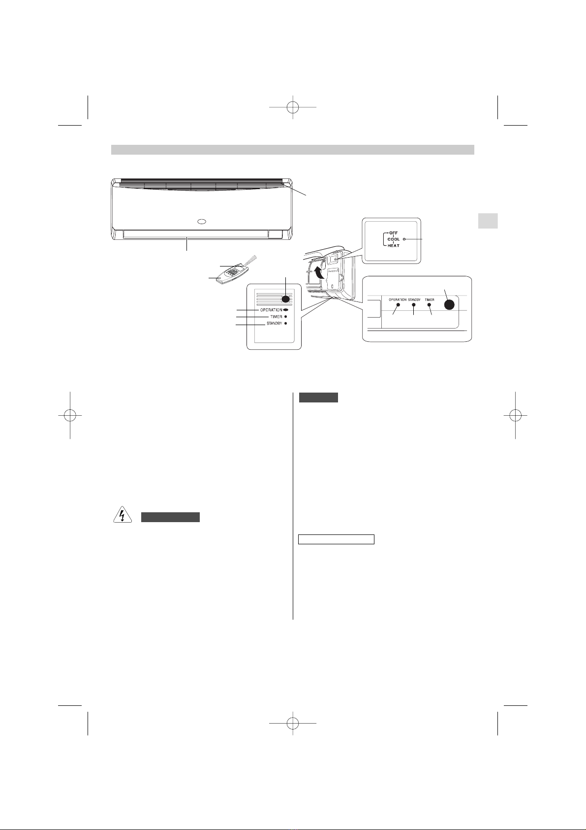
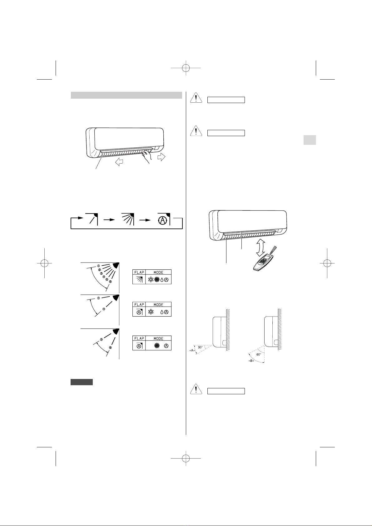
TEMPERATURE SENSOR SELECTOR
lUnder normal conditions the room temperature is detected
and checked by the temperature sensor placed in the
remote controller (I FEEL icon displayed ).This function
is designed to provide a comfortable room temperature
by transmitting the temperature control command from the
location next to you. When using this function, the remote,
control should always be pointed at the air conditioner,
therefore it should be placed in a position in which it is
visible by the indoor unit (for example, do not put it in a
drawer).
lIt is possible to disable the remote controller room sensor
pressing the I FEEL button. In this case the I FEEL icon
on the remote controller display lights off and only the
sensor placed in the air conditioner becomes active.
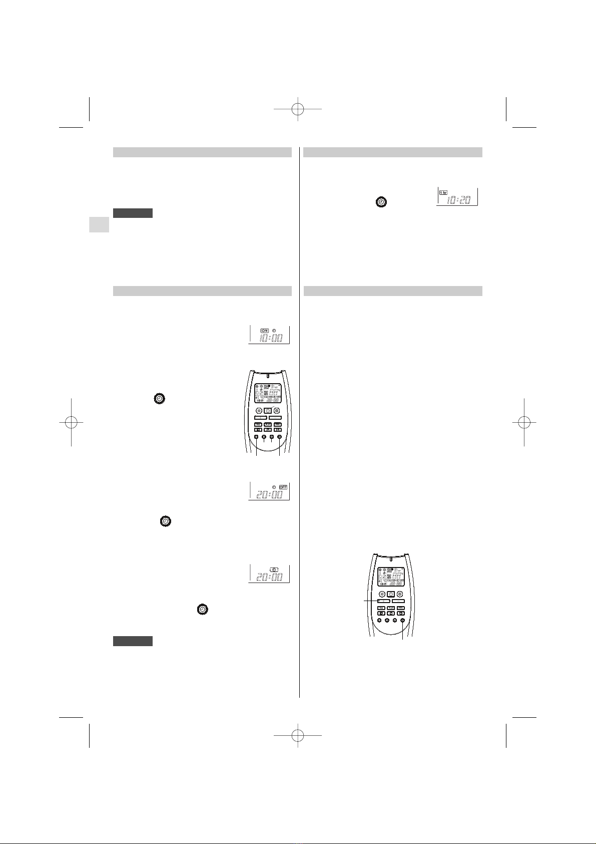
USING THE REMOTE CONTROL UNIT
lInsert two AAA alkaline batteries of 1,5 V-DC making
sure that point in the direction marked in the battery
compartment.The displayed time flashes.
Press the SEL TYPE button.
Remote controller is now ready for operation.
lThe batteries last average more than six months, anyway
it depends on how much you use the remote control
unit.
Remove the batteries if you do not use the remote control
unit for more than one month.
Replace the batteries when the remote control unit lamp
fails to light, or when the air conditioner does not receive
the remote control unit signals.
lThe batteries of the remote control contain polluted
substances. Exhausted batteries must be disposed
according to the laws in force.
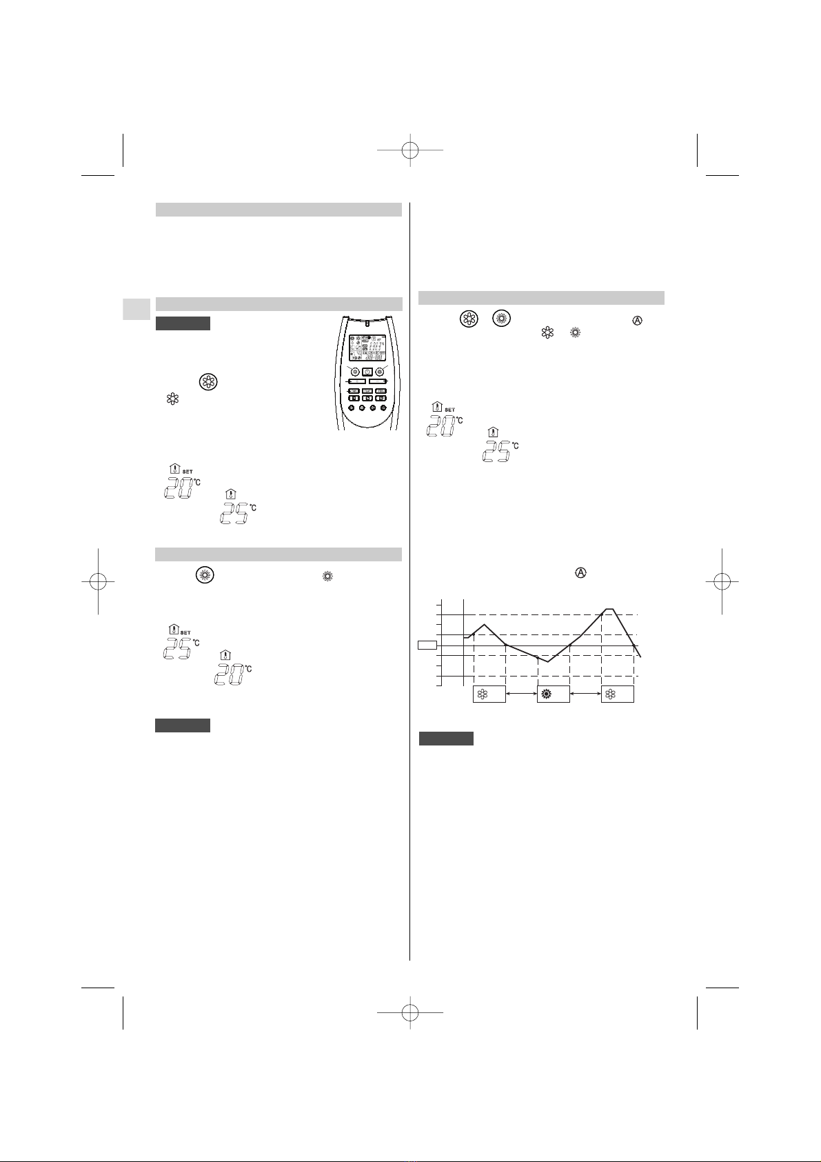
OPERATION WITH THE REMOTE CONTROL UNIT
When using the remote control unit, always point the unit
transmitter head directly at the air conditioner receiver.
HOW TO TURN ON THE AIR CONDITIONER
Press the ON/OFF button to turn the air conditioner on.
The operation lamp will light up, indicating the unit is in
operation.
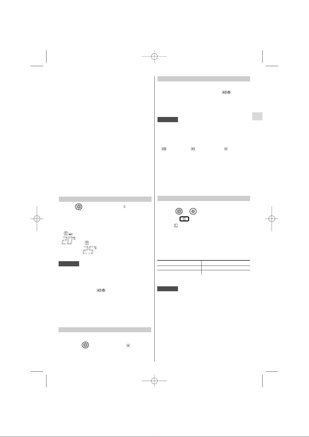
The remote control unit transmits signals to the indoor
unit each time you press a key and at any temperature
change detected by the IFEEL sensor. In case of
troubles (low batteries, remote control placed in a
position not visible by the indoor unit,...) room
temperature control is automatically switched to the
sensor of the indoor unit. In this case, the temperature
around the remote control unit may differ from the
temperature detected in the air conditioner position.
NOTE
SWITCHES
NOTE IF YOU INSTALL MORE THAN ONE INDOOR
UNIT IN THE SAME ROOM:
It is possible to utilise only one remote control for all
the units.
On the contrary, if you want to address each remote
control to its unit, follow the procedure”Remote control
unit/indoor unit address” (see Installation Instructions).
PLEASE, SEE THE END
OF THIS MANUAL FOR
DETAILS