Argo X3I ECO FC26HL Operating manual

3OHDVHUHDGWKLVPDQXDOFDUHIXOO\EHIRUHLQVWDOOLQJDQGXVLQJWKHDLUFRQGLWLRQHUDQGUHWDLQIRUIXWXUH
UHIHU
HQFH
;(&23/86
FLOOR/CEILING,1'22581,76
)2508/7,63/,7±5
86(5DQG,167$//$7,210$18$/
,1'22581,76
;,(&2)&+/
;,(&2)&+/
;,(&2)&+/
901/20

Contents
1 Safety Precautions............................................................... 1
2 Outline of the Unit and Main Parts ....................................... 2
4 Preparative for Installation ..................................................10
4.1 Standard Accessory Parts ....................................................10
4.2 Selection of the Installation Location ....................................10
4.3 Connection Pipe Requirement .............................................11
4.4 Electrical Requirement .........................................................12
3.5 Operation guide.......................................................................9
3.6 Replacement of batteries in remote controller...........................................9
3 Operation of remote controller................................................3
3.1 Buttons on remote controller ..................................................3
3.2 Introduction for icons on display screen..................................3
3.3 Introduction for buttons on remote controller...........................4
3.4 Function introduction for combination buttons...........................................8
5 Installation of the Unit .........................................................13
5.1 Installation of the Indoor Unit................................................13
5.2 Installation of the Connection Pipe .......................................16
5.3 Vacuum and Gas Leakage Inspection ..................................20
5.4 Installation of the Drain Pipe ................................................22
5.5 Electrical Wiring ...................................................................25
6 Installation of Controllers ................................................... 29
7 Test Running...................................................................... 30
7.1 Trial Operation and Testing ..................................................30
8 Troubleshooting and Maintenance..................................... 32
8.1 Troubleshooting ...................................................................32
8.2 Routine Maintenance ...........................................................33

The Refrigerant
ƔTo realize the function of the air conditioner unit, a special refrigerant circulates
.
leads to explosion
. It can
ƔCompared to common refrigerants, R32 is a nonpolluting refrigerant with no
lower. R32 has got very good thermodynamic features which lead to a really high
WARNING:
Do not use means to accelerate the defrosting process or to clean, other than
those recommended by the manufacture.Should repair be necessary, contact your
nearest authorized Service Centre.
The appliance shall be stored in a room without continuously operating ignition
electric heater.)
Do not pierce or burn.
than “X”m (see table 1).(only applies to appliances that are not fixed appliances)
Appliance shall be installed, operated and stored in a room with a floor area larger
2
’s
instructions only.
Be aware that refrigrants not contain odour.
Read specialist’s manual.
Please read this operating manual carefully before operating the unit.
to the material objects for reference.

Floor Ceiling Type Unit
1
1 Safety Precautions
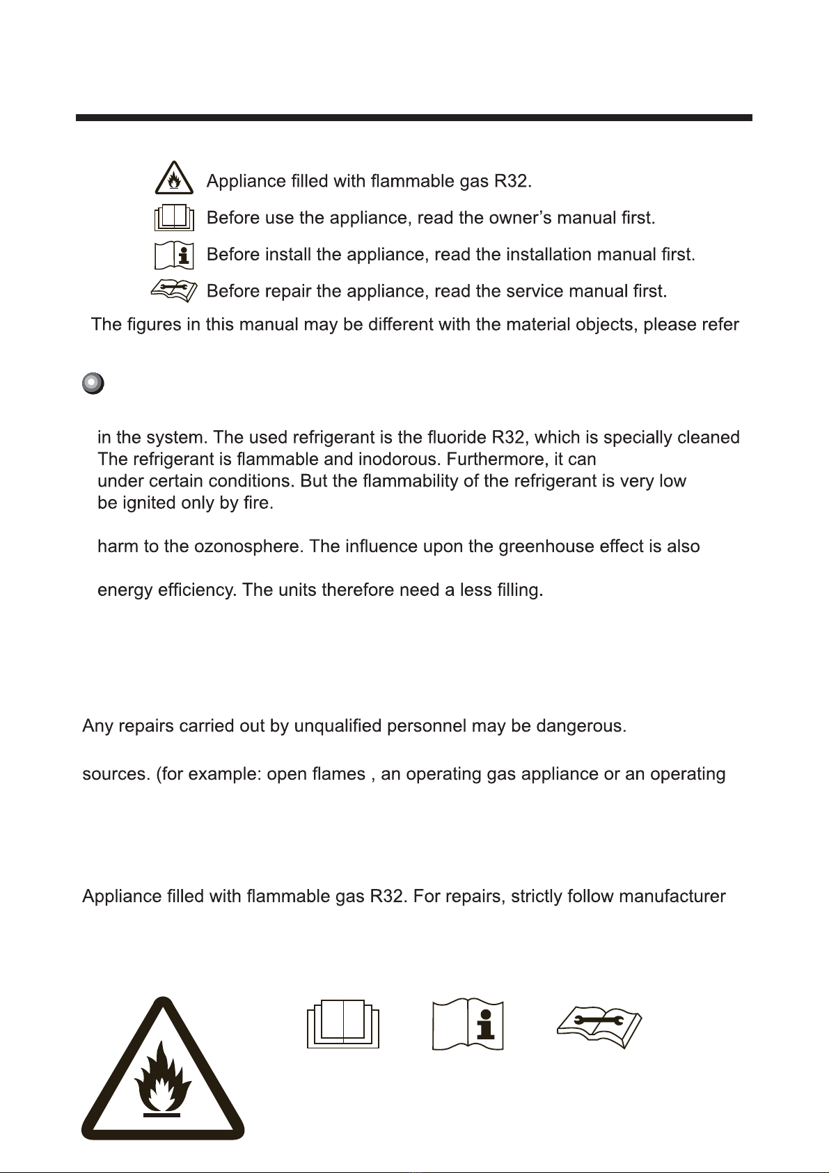
WARNING! This mark indicates procedures which, if improperly performed, might lead to
the death or serious injury of the user.
CAUTION! This mark indicates procedures which, if improperly performed, might
possibly result in personal harm to the user, or damage to property.
WARNING!
(1). For operating the air conditioner pleasantly, install it as outlined in this installation manual.
(2). Connect the indoor unit and outdoor unit with the room air conditioner piping and cord
available from our standard parts. This installation manual describes the correct connections
using the installation set available from our standard parts.
(3). Installation work must be performed in accordance with national wiring standards by
authorized personnel only.
(4). If refrigerant leaks while work is being carried out, ventilate the area. If the refrigerant comes in
contact with a flame, it produces toxic gas.
(5). Do not power on until all installation work is complete.
(6). During installation, make sure that the refrigerant pipe is attached firmly before you run the
compressor.
Do not operate the compressor under the condition of refrigerant piping not attached properly
with 2-way or 3-way valve open.
This may cause abnormal pressure in the refrigeration cycle that leads to breakage and even
injury.
(7). During the pump-down operation, make sure that the compressor is turned off before you
remove the refrigerant piping.
Do not remove the connection pipe while the compressor is in operation with 2-way or 3-way
valve open.
This may cause abnormal pressure in the refrigerant cycle that leads to breakage and even
injury.
(8). When installing and relocating the air conditioner do not mix gases other than the specified
refrigerant (R32) to enter the refrigerant cycle.
If air or other gas enters the refrigerant cycle, the pressure inside the cycle will rise to an
abnormally high value and cause breakage, injury, etc.
(9). This appliance can be used by children aged from 8 years and above and persons with
reduced physical, sensory or mental capabilities or lack of experience and knowledge if they
have been given supervision or instruction concerning use of the appliance in a safe way and
understand the hazards involved. Children shall not play with the appliance. Cleaning and
user maintenance shall not be made by children without supervision.
(10). If the supply cord is damaged, it must be replaced by the manufacturer, its service agent or
similarly qualified persons in order to avoid a hazard.
(11). Correct Disposal of this product
(12). The appliance shall not be installed in the laundry.
GWP˖
R32:675
This marking indicates that this product should not be disposed with other
household wastes throughout the EU. To prevent possible harm to the
environment or human health from uncontrolled waste disposal, recycle it
responsibly to promote the sustainable reuse of material resources. To
return your used device, please use the return and collection systems or
contact the retailer where the product was purchased. They can take this
product for environmental safe recycling.

Floor Ceiling Type Unit
2
2 Outline of the Unit and Main Parts
Fig.1
Notes: The connection pipe and duct for this unit should be prepared by the user.

7
2
1
8
10
12
15
14
13
11
9
6
5
4
3
1ON/OFF button
2MODE button
3+/- button
4FAN button
5I FEEL button
11 X-FAN button
Note: X-FAN is the same with BLOW
12 TEMP button
13 TURBO button
15 LIGHT button
14 SLEEP button
10 TIMER ON/TIMER OFF
button
9CLOCK button
Send signal
Turbo mode
X-fan mode
Set temperature
Set time
TIMER ON / TIMER OFF
Child lock
Up & down swing
Set fan speed
AIR function
I feel
Light
Temp. display type
:Set temp.
:Outdoor ambient temp.
:Indoor ambient temp.
Sleep mode
Clock
Health function
Heat mode
Fan mode
Dry mode
Cool mode
Auto mode
Operation mode
8button
6button
7button
)ORRU&HLOLQJ7\SH8QLW
3 Operation of remote controller
3.1 Buttons on remote controller
3.2 Introduction for icons on display screen

4
Floor Ceiling Type Unit
Ɣ $IWHUVHOHFWLQJDXWRPRGHDLUFRQGLWLRQHUZLOORSHUDWHDXWRPDWLFDOO\DFFRUGLQJWR
DPELHQWWHPSHUDWXUH6HWWHPSHUDWXUHFDQ¶WEHDGMXVWHGDQGZLOOQRWEHGLVSOD\HG
DVZHOO3UHVVF$1EXWWRQFDQDGMXVWIDQVSHHG3UHVVEXWWRQFDQDGMXVW
IDQEORZLQJDQJOH
Ɣ $IWHUVHOHFWLQJFRROPRGHDLUFRQGLWLoQHUZLOORSHUDWHXQGHUFRROPRGH3UHVV
RUEXWWRQWRDGMXVWVHWWHPSHUDWXUH3UHVV)1EXWWRQWRDGMXVWIDQVSHHG
3UHVVEXWWRQWRDGMXVWIDQEORZLQJDQJOH
Ɣ :KHQVHOHFWLQJGU\PRGHWKHDLUFRQGLWLRQHURSHUDWHVDWORZVSHHGXQGHUGU\
PRGH8QGHUGU\PRGHIDQVSHHGFDQ¶WEHDGMXVWHG3UHVVEXWWRQWRDGMXVW
IDQEORZLQJDQJOH
Ɣ :KHQVHOHFWLQJIDQPRGHWKHDLUFRQGLWLRQHUZLOORQO\EORZIDQQRFRROLQJDQG
QRKHDWLQJ $OOLQGLFDWRUVDUH2)F2SHUDWLRQLQGLFDWRULV213UHVVF$1EXWWRQ
WRDGMXVWIDQVSHHG3UHVV
Ɣ :KHQVHOHFWLQJKHDWLQJPRGHWKHDLUFRQGLWLRQHURSHUDWHVXQGHUKHDWPRGH
3UHVVRUEXWWRQWRDGMXVWVHWWHPSHUDWXUH3UHVV)$1EXtton to DGMXVW
IDQ VSHHG3UHVVEXtton to DGMXVWIDQEORZLQJDQJOH&RROLQJRQO\XQLW ZRQ¶W
UHFHLYHKHDWLQJPRGHVLJQDO,IVHWWLQJKHDWPRGHZLWKUHPRWHFRQWUROOHrSUHVV
212))EXWWRQFDQ¶WVWDUWXSWKHXQLW
Note:
Ɣ )RUSUHYHQWLQJFROGDLrDIWHUVWDUWLQJXSKHDWLQJPRGHLQGRRUXQLWZLOOGHOD\a
PLQXWHVWREORZDLUDFWXDOGHOD\WLPHLVGHSHQGRQLQGRRUDPELHQWWHPSHUDWXUH
Ɣ 6HWWHPSHUDWXUHUDQJHIURPUHPRWHFRQWUROOHUać)DQVSHHGDXWRORZ
VSHHGPHGLXPVSHHGKLJKVSHHG
Note:
Ɣ $IWHUSXWWLQJWKURXJKWKHSRZHrWKHDLUFRQGLWLRQHUZLOOJLYHRXWDVRXQG
$IWHUWKDW\RXFDQRSHUDWHWKHDLUFRQGLWLRQHUE\XVLQJUHPRWHFRQWUROler
212))EXWWRQ
02'(EXWWRQ
1
2
3UHVVWKLVEXWWRQFDQWXUQRQRUWXUQRIIWKHDLUFRQGLWLRQHr$IWHUWXUQLQJRQWKHDLU
FRQGLWLRQHrRSHUDWLRQLQGLFDWRURQLQGRRUXQLt¶VGLVSOD\LV21JUHHQLQGLFDtor
7KHFRORXULVGLIIHUHQWIRUGLIIHUHQWPRGHOVDQGLQGRRUXQLWZLOOJLYHRXWDVRXQG
3UHVVWKLVEXWWRQWRVHOHFW\RXUUHTXLUHGRSHUDWLRQPRGH
$8T2 &22/ F$1'RY +($T
EXWWRQWRDGMXVWIDQEORZLQJDQJOH
Ɣ 7KLVLVDJHQHUDOXVHUHPRWHFRQWUROOHULWFRXOGEHXVHGIRUWKHDLUFRQGLWLRQHUV
ZLWKPXOWLIXQFWLRQ)RUVRPHIXQFWLRQZKLFKWKHPRGHOGRHVQWKDYHLISUHVV
WKHFRUUHVSRQGLQJEXWWRQRQWKHUHPRWHFRQWUROOHUWKDWWKHXQLWZLOONHHSWKH
RULJLQDOUXQQLQJVWDWXV
,QWURGXFWLRQIRUEXWWRQVRQUHPRWHFRQWUROOHU

FAN button
I FEEL button
4
5
6
7
Pressing this button can set fan speed circularly as: auto (AUTO), low( ) ,medium
( ), high( ).
Note:
Ɣ 8QGHU AUTO Speed,IDU fan motor will adjust the fan speed (high, medium or
low speed) according to ambient temperature.
Ɣ )DQVSHHGXQGHUGU\PRGHLVORZVSHHd.
Press this button to start I FEEL function and " " will be displayed on the remote
controller. After this function is set, the remote controller will send the detected
ambient temperature to the controller and the unit will automatically adjust the
indoor temperature according to the detected temperature. Press this button again
to close I FEEL function and " " will disappear.
Ɣ 3OHDVHSXWWKHUHPRWHFRQWUROOHUQHDUXser when this function is set. Do not put
the remote controller near the object of high temperature or low temperature in
order to avoid detecting inaccurate ambient temperature.
Press this button to set HEALTH function ON or OFF. After the unit is turned on, it
defaults to HEALTH function ON.
Press this button to select AIR function ON or OFF.
button
button
(Only available for some models)
Ɣ 7KLVIXQFWLRQLVDSSOLFDEOHWRSDUWLDORIPRGHOV
Auto
+/- button
3
Ɣ 3UHVVRUEXWWRQRQFHLQFUHDVHRUGHFUHDVHVHWWHPSHUDture 1ć.
Holding "+" or "-" button, 2s later, set temperature on remote controller will
tor on indoor unit will change accordingly. (Temperature can’t be adjusted under
auto mode)
Ɣ :KHQVHWWLQJ TIMER ON, TIMER OFF or CLOCK, press "+" or "-" button to
adjust time. (Refer to CLOCK, TIMER ON, 7,0(52))EXWWRQV:KHQVHWWLQJ
TIMER ON, TIMER OFF or CLOCK, press "+" or "-" button to adjust time. (Refer
to CLOCK, TIMER ON, TIMER OFF buttons)
Ɣ :KHQ,)((/IXQFWLRQLVWXUQHGRQWKHUHPRWHFRQWUROOHUVKRXOGEHSXWZLWKLQWKH
area where indoor unit can receive the signal sent by the remote controller.
)ORRU&HLOLQJ7\SH8QLW

Press this button to set clock time. " " icon on remote controller will blink. Press
"+" or "-" button within 5s to set clock time. Each pressing of "+" or "-" button, clock
time will increase or decrease 1 minute. If hold "+" or "-" button, 2s later, time will
change quickly. Release this button when reaching your required time. Press
&/2&.EXWWRQWRFRQ¿UPWKHWLPHLFRQVWRSVEOLQNLQJ
Note:
Ɣ &ORFNWLPHDGRSWVKRXUPRGH
ƔThe interval between two operation can’t exceeds 5s. Otherwise, remote contro-
ller will quit setting status. Operation for TIMER ON/TIMER OFF is the same.
CLOCK button
9
TIMER ON / TIMER OFF button
10
ƔTIMER ON button
"TIMER ON" button can set the time for timer on. After pressing this button, " "
icon disappears and the word "ON" on remote controller blinks. Press "+" or "-"
button to adjust TIMER ON setting. After each pressing "+" or "-" button, TIMER
ON setting will increase or decrease 1min. Hold "+" or "-" button, 2s later, the
time will change quickly until reaching your required time.
3UHVV7,0(521WRFRQ¿UPLW The word "ON" will stop blinking. " " icon
resumes displaying. Cancel TIMER ON: Under the condition that TIMER ON is
8
Press this button can select up&down swing angle. Fan blow angle can be selected
circularly as below:
Ɣ :KHQVHOHFWLQJDLUFRQGLWLRQHULVEORZLQJIDQDXWRPDWLFDOO\. Horizontal
louver will automatically swing up & down at maximum angle.
Ɣ :KHQVHOHFWLQJ ǃǃǃǃ
DLUFRQGLWLRQHULVEORZLQJIDQDW¿[HG
SRVLWLRQ+RUL]RQWDOORXYHUZLOOVWRSDWWKH¿[HGSRVLWLRQ
Ɣ :KHQVHOHFWLQJ ǃǃ
DLUFRQGLWLRQHULVEORZLQJIDQDW¿[HGDQJOH
+RUL]RQWDOORXYHUZLOOVHQGDLUDWWKH¿[HGDQJOH
Ɣ +ROGEXWWRQDERYHVWRVHW\RXUUHTXLUHGVZLQJDQJOH:KHQUHDFKLQJ\RXU
required angle, release the button.
Note:
Ɣ ǃǃ
PD\QRWEHDYDLODEOH:KHQDLUFRQGLWLRQHUUHFHLYHVWKLVVLJQDOWKH
air conditioner will blow fan automatically.
button
no display
(horizontal louvers stops
at current position)
)ORRU&HLOLQJ7\SH8QLW

started up, press "TIMER ON" button to cancel it.
ƔTIMER OFF button
"TIMER OFF" button can set the time for timer off. After pressing this button," "
icon disappears and the word "OFF" on remote controller blinks. Press "+" or "-"
button to adjust TIMER OFF setting. After each pressing "+" or "-" button, TIMER
OFF setting will increase or decrease 1min. Hold "+" or "-" button, 2s later, the
time will change quickly until reaching your required time.
Press "TIMER OFF" word "OFF" will stop blinking. " " icon resumes displaying.
Cancel TIMER OFF. Under the condition that TIMER OFF is started up, press
"TIMER OFF" button to cancel it.
Note:
Ɣ 8QGHURQDQGRff status, you can set TIMER OFF or TIMER ON simultaneously.
Ɣ %HIRUHVHWWLQJ TIMER ON or TIMER OFF, please adjust the clock time.
ƔAfter starting up TIMER ON or TIMER OFF, set the constant circulating valid.
After that, air conditioner will be turned on or turned off according to setting time.
ON/OFF button has no effect on setting. If you don’t need this function, please
use remote controller to cancel it.
X-FAN button
11
12
Press this button under cool and dry mode to start up x-fan function, and " " icon
on remote controller will be displayed. Press this button again to cancel x-fan
function, and " "icon will disappear.
Note:
Ɣ :KHQ[IDQIXQFWLRQLVRQLIWKHDLUFRQGLWLRQHULVWXUQHGRIf, indoor fan will still
operate at low speed for a while to blow the residual water inside the air duct.
Ɣ 'XULQJ[IDQRSHUDWLRQSUHVV;FAN button to turn off x-fan function. Indoor fan
will stop operation immediately.
TEMP button
%\SUHVVLQJWKLVEXWWRQ\RXFDQVHHLQGRRUVHWWHPSHUDWXUHLQGRRUDPELHQWWHPS
erature or outdoor ambient temperature on indoor unit’s display. The setting on
remote controlleris selected circularly as below:
no display
Ɣ :KHQVHOHFWLQJRUQRGLVSOD\ZLWKUHPRWHFRQWUROOHr, temperature indicator
on indoor unit displays set temperature.
Ɣ:KHQVHOHFWLQJZLWKUHPRWHFRQWUROOHr, temperature indicator on indoor unit
displays indoor ambient temperature.
)ORRU&HLOLQJ7\SH8QLW

TURBO button
13
Under COOL or HEAT mode, press this button to turn to quick COOL or quick
HEAT mode. " " icon is displayed on remote controller. Press this button again
to exit turbo function and " " icon will disappear.
Child lock function
Press "+" and "-" simultaneously to turn on or turn off child lock function. When
child lock function is on, " " icon is displayed on remote controller. If you operate
the remote controller, the " " icon will blink three times without sending signal to
the unit.
Temperature display switchover function
Under OFF status, press "-" and "MODE" buttons simultaneously to switch temp-
erature display between ćand .
Press this button to turn off display light on indoor unit. " " icon on remote
controller disappears. Press this button again to turn on display light. " " icon is
displayed.
SLEEP button
LIGHT button
14
15
Ɣ :KHQVHOHFWLQJZLWKUHPRWHFRQWUROOHr, temperature indicator on indoor unit
displays outdoor ambient temperature.
Note:
Ɣ
Outdoor temperature display is not available for some models. At that time, indoor
unit receives " "signal, while it displays indoor set temperature.
Ɣ,W’s defaulted to display set temperature when turning on the unit.There is no
display in the remote controller.
Ɣ 2QO\IRUWKHPRGHOVZKRVHLQGRRUXQLWKDVGXDOGLVSODy.
Ɣ :KHQVHOHFWLQJGLVSOD\LQJRILQGRRURURXWGRRUDPELHQWWHPSHUDWXUHLQGRRU
temperature indicator displays corresponding temperature and automatically turn
Under COOL, HEAT mode, press this button to start up sleep function. " " icon
is displayed on remote controller. Press this button again to cancel sleep function and
" " icon will disappear.
Floor Ceiling Type Unit
3.4 Function introduction for combination buttons

1. After putting through the power, press "ON/OFF" button on remote controller to
turn on the air conditioner.
2. Press "MODE" button to select your required mode: AUTO, COOL, DRY, FAN,
HEAT.
3. Press "+" or "-" button to set your required temperature. (Temperature can’t be
adjusted under auto mode).
4. Press "FAN" button to set your required fan speed: auto, low, medium and high
speed.
5. Press " " button to select fan blowing angle.
1. Press the back side of remote controller marked
the cover of battery box along the arrow direction.
2. Replace two 7# (AAA 1.5V) dry batteries, and
make sure the position of "+" polar and "-" polar
are correct.
3. Reinstall the cover of battery box.
signal sender battery
Cover of battery box
remove
reinstall
NOTICE
Ɣ 'XULQJRSHUDWLRQSRLQWWKHUHPRWHFRntrol signal sender at the receiving
window on indoor unit.
ƔThe distance between signal sender and receiving window should be no
more than 8m, and there should be no obstacles between them.
or wireless telephone; remote controller should be close to indoor unit during
operation.
Ɣ 5HSODFHQHZEDWWHULHVRIWKHVDPHPRGHOZKHQUHSODFHPHQWLVUHTXLUHG
Ɣ :KHQ\RXGRQ¶WXVHUHPRWHFRQWUROOHUIRUDORQJWLPHSOHDVHWDNHRXWWKH
batteries.
Ɣ ,IWKHGLVSOD\RQUHPRWHFRQWUROOHULVIX]]\RUWKHUH’s no display, please
replace batteries.
3.5 Operation guide
3.6 Replacement of batteries in remote controller
9
Floor Ceiling Type Unit

Floor Ceiling Type Unit
Preparative for Installation
.1 Standard Accessory Parts
The standard accessory parts listed below are furnished and should be used as
required.
Table 1
Indoor Unit Accessories
No. Name Appearance Q'ty Usage
1 Nut with Washer 8To fix the hook on the
cabinet of the unit.
2Wireless Controller +
Battery 1+2 To control the indoor unit
3 Insulation 1 To insulate the gas pipe
4 Insulation 1 To insulate the liquid pipe
5 Installation Paperboard 2 To insulate the drain pipe
6 Fastener 4 To fasten the sponge
7Nut 1 To connect gas pipe
8Nut 1 To connect liquid pipe
.2 Selection of the Installation Location
Decide the installation location with the customer as follows:
WARNING!
The unit must be installed where strong enough to withstand the weight of the unit and fixed securely
otherwise the unit would topple or fall off.
CAUTION!
ķ.Do not install where there is a danger of combustible gas leakage.
ĸ.Do not install the unit near heat source, steam, or flammable gas.
Ĺ.Children under 10 years old must be supervised not to operate the unit.

Floor Ceiling Type Unit
.2.1 Indoor Unit
(1). Install the unit at a place where is strong enough to withstand the weight of
the unit.
(2). The air inlet and outlet of the unit should never be clogged so that the
airflow can reach every corner of the room.
(3). Leave service space around the unit as required in Fig. 2
Fig. 2
(4). Install the unit where the drain pipe can be easily installed.
(5). The space from the unit to the ceiling should be kept as much as possible
so as for more convenient service.
.3 Connection Pipe Requirement
CAUTION!
The maximum length of the connection pipe is listed in the Table below. Do not place the units
between which the distance exceeds the maximum length of the connection pipe.

Table 2
(1). The connecting pipe should be thermally insulated properly.
(2). The pipe wall thickness shall be 0.5-1.0 mm and the pipe wall shall be able
to withstand the pressure of 6.0 MPa. The longer the connecting pipe, the
lower the cooling and heating effect performs.
(3). The pipe wall thickness shall be 0.5-1.0mm and the pipe wall shall be able
to withstand the pressure of 6.0 MPa. The longer the connecting pipe, the
lower the cooling and heating effect performs.
Item
Model
Size of Fitting Pipe(Inch) Max.
Pipe
Length
(m)
Max. Height
Difference
between Indoor
Unit and Outdoor
Unit (m)
Indoor unit
Drainage
pipe(Outer
Diameter ×
wall thickness)
(mm)
Liquid Gas
1/4 3/8 20 10 ĭ17×1.75
1/4 1/2 20 10 ĭ17×1.75
Floor Ceiling Type Unit
.4 Electrical Requirement
Electric Wire Sizeand Fuse Capacity.
Table 3
Notes:
ķ. The fuse is located on the main board.
ĸ. Install the disconnect device with a contact gap of at least 3 mm in all poles
nearby the units (Both indoor unit and outdoor unit).The appliance must be
positioned so that the plug is accessible.
Ĺ. The specifications of WKH power cable listed in the Table above
are determined based on the maximum power (maximum amps) of the unit.
ĺ. The specifications of the power cable listed in the Table above are applied to
the conduit-guarded multi-wire copper cable (like, YJV copper cable,
consisting of PE insulated wires and a PVC cable jacket) used at 40ɋand
resistible to 90ɋ(see IEC 60364-5-52). If the working condition changes, they
should be modified according to the related national standard.
Indoor Units
Power Supply Fuse
Capacity
Min. Power
Supply Cord
V/Ph/Hz Amm2
9~24k 220-240V~
50Hz 50.75

Floor Ceiling Type Unit
13
5 Installation of the Unit
5.1 Installation of the Indoor Unit
5.1.1 Indoor unit dimension
Fig. 3
WARNING !
ķ. Install the indoor unit in a location which can withstand a load of at least five times the
weight of the main unit and which will not amplify sound or vibration.
ĸ. If the installation location is not strong enough, the indoor unit may fall and cause injuries.
Ĺ. If the job is done with the panel frame only, there is a risk that the unit will come loose.
Please take care.

Floor Ceiling Type Unit
Table Unit: mm
.1.2 Preparation for Installing the Indoor Unit
(1). Open the air inlet grille and the screw cover, and remove the screws.
(2). Release the claws in the 3 places indicated.
(3). Release the center hook and remove the front panel.
(4). Release the claws in the 2 or 3 places indicated and remove the electric
component cover.
.1.3 Indoor Unit Installation
(1). Determine the location of the hanger through the paper template, and then
remove the paper template.
Fig.
(2). Insert the anchor bolts into the drilled holes, and drive the pins completely
into the anchor bolts with a hammer.
(3). Remove the right and left side panels.
(4). Put the hanger bolt into the clasp of the indoor unit and tighten screws on
the hanger to prevent the indoor unit from moving.
Model A B C D H
870 235 812 318 665

Floor Ceiling Type Unit
(5). Adjust the height of the unit to make the drain pipe slant slightly downward
so that the drainage will become much smoother.
ƹFloor type
Fig.
ƹCeiling type
Fig.
(6). Reinstall and tighten the right and left side panel.

Floor Ceiling Type Unit
.1.4 Leveling
The water level test must be done after installing the indoor unit to make the
unit is horizontal, as shown below.
Fig.
.Installation of the Connection Pipe
..1 Flare Processing
(1). Cut the connection pipe with the pipe cutter and remove the burrs.
(2). Hold the pipe downward to prevent cuttings from entering the pipe.
(3). Remove the flare nuts at the stop valve of the outdoor unit and inside the
accessory bag of the indoor unit, then insert them to the connection pipe,
after that, flare the connection pipe with a flaring tool.
(4). Check if the flare part is spread evenly and there are no cracks (see Fig.
Fig.

..2 Bending Pipes
(1). The pipes are shaped by your hands. Be careful not to collapse them.
Fig.
(2). Do not bend the pipes in an angle more than 90°.
(3). When pipes are repeatedly bent or stretched, the material will harden,
making it difficult to bend or stretch them any more. Do not bend or stretch
the pipes more than three times.
(4). When bending the pipe, do not bend it as is.
The pipe will be collapsed. In this case, cut
the heat insulating pipe with a sharp cutter as
shown in Fig. 1, and bend it after exposing
the pipe. After bending the pipe as you want,
be sure to put the heat insulating pipe back
on the pipe, and secure it with tape.
Fig. 1
CAUTION!
ķ.To prevent breaking of the pipe, avoid sharp bends. Bend the pipe with a radius of
curvature of 150 mm or over.
ĸ.If the pipe is bent repeatedly at the same place, it will break.
Floor Ceiling Type Unit
This manual suits for next models
4
Table of contents
Other Argo Air Conditioner manuals

Argo
Argo AEI1G50EMX/BB User manual

Argo
Argo POLIFEMO BEAR User manual

Argo
Argo Husky User manual

Argo
Argo ECOLIGHT 18000 UI WIFI User manual

Argo
Argo LUDVIG User manual

Argo
Argo POLIFEMO BILLY User manual

Argo
Argo X3 ECO PLUS Operating manual

Argo
Argo POLIFEMO CLASS White User manual

Argo
Argo AS 425 C Manual

Argo
Argo AWMI28AHL User manual
Popular Air Conditioner manuals by other brands

Toyotomi
Toyotomi IZURU Series WiFi User’s manual

Trotec
Trotec PAC 3550 PRO operating manual

Fujitsu
Fujitsu AU G45LRLA Series Design & technical manual

Polocool
Polocool PC-53AP/C user manual

Venmar
Venmar 41502 installation guide

Frigidaire
Frigidaire GAC122P1A - GIBSON 12000BTU 115V 9.8EER3 SPD 8 WAY AIR... installation instructions