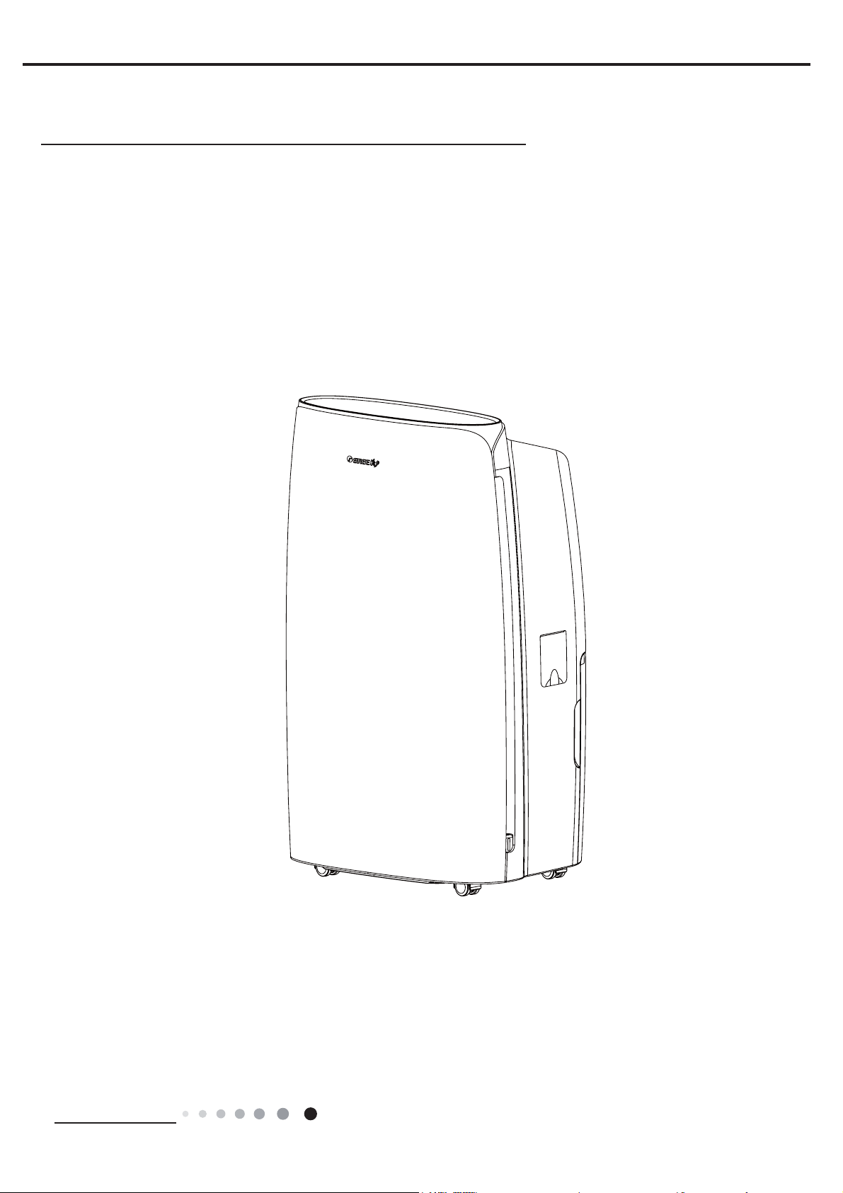
Argo Dry 41 User manual

1
V 06/16
DEHUMIDIFIER
OPERATING INSTRUCTIONS
EN
Dry 41

Service Manual
Table of Contents
Table of Contents
Part : Technical Information
1. Summary
3. Outline Dimension Diagram
4. Refrigerant System Diagram
5. Electrical Part
5.1 Wiring Diagram
5.2 PCB Printed Diagram
6. Function and Control
Part : Maintenance
7. Notes Maintenance
8. Maintenance
9. Removal Procedure
Appendix:
Appendix 1: Reference Sheet of Celsius and Fahrenheit
Appendix 2: Resistance Table of Ambient Temperature Sensor
Appendix 3: Resistance Value Table of Humidity Sensor

Technical Information
Service Manual
1.Summary
Part Ė: Technical Information

Sr No Unit Value
1 -- PLATINUM 41
Rated Voltage V220-240
Rated Frequency Hz 50
Phases -- 1
4 L/h 1.00
5 L/D 24.0
6 Pint/D 51
7 kg/h /
8 L/h 1.66
9 W 570
10 W 725
11 A 2.65
12 W 700
13 A 3.1
14 m3/h 230/195/170
15 CFM 135/115/100
16 m248
17 dB (A) 46/43/41
18 dB (A) 56/53/51
19 -- Centrifugal
20 mm 192x66
21 inch 7 1/2x2 3/5
22 r/min 1260/1070/900
23 W20
24 A 0.35
25 F 2
26 MPa 4.3
27 MPa 2.5
28 MPa 4.3
29 % 30/80
30 -- Capillary
31 -- T1
32 -- I
33 -- IP21
34 A 3.15
35 L 6.5/7
36 -- Electronic
37 mm 396×625×286
38 inch 15.591×24.606×11.26
39 mm 448×338×638
40 inch 17.638×13.307×25.118
41 mm 451×341×653
42 inch 17.756×13.425×25.709
43 kg 23
44 kg 24.5
6SHFLILFDWLRQV
Fan Type
Fan Motor RLA
Throttling Method
Permissible Excessive Operating Pressure for the Discharge Side
Fan Motor Speed
Fan Motor Power Output
Permissible Excessive Operating Pressure for the Suction Side
Set Humidity Range
Air Flow Volume(H/M/L)
Sound Pressure Level (H/M/L)
Sound Power Level ((H/M/L)
Application Area
Isolation
Parameter
Model
Power Input
Rated Dehumidification Capacity
Power Input of Dehumidification Capacity
Dehumidification Capacity
Fan Motor Capacitor
3Power
Supply
Rated Dehumidification Capacity
Rated Current
Fan Diameter Length(DhL)
Net Weight
Gross Weight
Rated Input
Air Flow Volume(H/M/L)
Current Input
Dimension of Package (L×W×H)
Moisture Protection
Maximum Allowable Pressure
Climate Type
Bucket Capacity
Fuse Current
Dimension (W×H×D)
Dimension of Package (L×W×H)
Dimension (W×H×D)
Dimension of Carton Box (L×W×H)
Control Type
Service ManualService Manual

46 kg 0.31
47 Compressor Trademark -- GREE
48 Compressor Manufacturer -- ZHUHAI LANDA
COMPRESSOR CO., LTD.
49 Compressor Model -- QXA-A071L130C
50 Compressor Type -- Rotary
51 Compressor LRA. A 15
52 Compressor RLA A 2.9
53 Compressor Power Input W 630
54 Compressor Overload Protector -- UP3-B0
55 Evaporator Form -- Aluminum Fin-copper
Tube
56 Evaporator Pipe Diameter mm 7
57 Evaporator Pipe Diameter inch 0.276
58 Evaporator Row-fin Gap mm 2-1.4
59 Evaporator Coil Length (LhDhW) mm 261X25.4X228.6
60 Evaporator Coil Length (LhDhW) inch 10 1/3X1X9
61 Condenser Form -- Aluminum Fin-copper
Tube
62 Condenser Pipe Diameter mm 7
63 Condenser Pipe Diameter inch 0.276
64 Rows-fin Gap mm 3-1.4
65 Condenser Coil Length (LhDhW) mm 261X38.1X228.6
66 Condenser Coil Length (LhDhW) inch 10 1/3X1 1/2X9
67 Loading Quantity
( 20’ Container ) unit 255
68 Loading Quantity
( 40’ Container ) unit 519
69 Loading Quantity
( 40’ High Cube Container ) unit 690
70 NO
71 YES
72 YES
73 YES
74 YES
75 NO
76 NO
77 YES
78 NO
79 YES
80 NO
81 YES
82 NO
83 YES
84 YES
85 YES
86 YES
87 YES
&RPSUHVVR
U
Tank Filled Protection
Self Diagnosis
)XQFWLRQ
5HODWHG
ZLWK3&%
Automatic Defrost
Real-time display of ambient humidity
Timer Feature
Removable Bucket/Location
External Drain Connector
Auto Swing(Horizontal Auto Swing)
I Feel
Auto Fan
Water Full Indicator
Air Flow
Memory
Quiet Design
Refrigerant Charge
Auto Swing(Vertical Auto Swing)
'HKXPLGLILHUV)XQFWLRQ
(YDSRUDWRU
Auto Swing(4-Dimension Swing)
Easy Roll Casters
Water Level Indicator/Location
/RDGLQ
TXDQWLW\
&RQGHQVHU
Service Manual

Technical Information
Service Manual
3.Outline Dimension Diagram
Unit:mm

Technical Information
Service Manual
4.Refrigerant System Diagram
air in
evaporator
capillary
condenser
fan motor
air out
compressor
dehumidifying the air by using this principle.
During operation of the system, air will pass through evaporator and condenser in turn and then be discharged due to centrifugal
blade. When the air is passing through evaporator, refrigerant will absorb the heat in air to let its temperature decrease to the
temperature point of dew, water vapor in air will condensate. Condensate water comes into water tank through water tray, or is
discharged directly through drainage hose. The saturated low-temperature air passed through the evaporator will absorb the heat

Technical Information
Service Manual
5.Electrical Part
Symbol Symbol Color Symbol Symbol Color Symbol Name
WH White GN Green CAP Jumper cap
YE Yellow BN Brown COMP Compressor
RD Red BU Blue Grounding wire
YEGN Yellow/Green BK Black / /
VT Violet OG Orange / /
5.1 Wiring Diagram
6
50
<(
%8
%8
&1
%8 %1
12
&206$
&203*/
57
/,48,'/(9(/
$3
&1
&1
$3
&1
+80,',7<
&1
6(1625
7(036(1625
78%(
$&/
©
)$1
02725
6:,7&+
67
&1
0
&1
3(
0
<(*1
&
3( &203
<(*1 &203
5'
&
1
3(
32:(5
1
<(*1
%1
%8 /
1
02725
67(33,1*
.
%1
5'
&
63610000330
PLATINUM 41

Technical Information
Service Manual
12 3 4 5
6
7
8109
Silk Screen on Main Board
5.2 PCB Printed Diagram
Top view
Bottom view
No. Name
1 Fuse
2Interface of display
board
3Compressor interface
without overcurrent
4Compressor interface
withovercurrent
5 Current mutual-inductor
6 Fan interface
7 Connect neutral wire
8 Piezoresistor
9Drive relay of
compressor
10 High-frequency
transformer

Technical Information
Service Manual
1
23 546
Top view
Bottom view
PLATINUM 41
No. Name
1 Boards connection interface for connection board
2 Interface of stepping motor
3 Interface of tube temperature sensor
4 Nixie tube
5 Interface of temperature and humidity sensor
6 Water level inspection interface
Silk Screen on Display Board

Technical Information
Service Manual
123456
Speed Indicator
Timer Indicator
Filter Cleaning
Indicator
Dehumidify Mode
Indicator
Bucket Full
Indicator
Display Window
Wind Direction Indicator
FanMode
Wind
Direc
Humidity Timer
High Med LowTimer ON/OFFSmart Cont Quiet DryWater Full Swing Fixed
Angle
Filter Clean
Notes:1.Water bucker must be correctly installed for operation.
2.Do not remove the bucket while unit is in operation.
3.If you want to use drain hose to drain water away, please install the hose according to section "Drainage method".
4.Each time pressing the effective button on the control panel will give out a "beep" sound.
simultaneously.
(1) ON/OFF Button
(2) Fan Button
Press Fan button can set high, medium or low fan speed. When thecorresponding indicator is on, it indicates the current fan speed
has been set.
(3) Timer Button
Press Timer button to set timer on or timer off. The timer can be set in 1h increment among 0-24h with each press of Timer button.
If hold the Timer button, time will increase rapidly circularly. After timer is set, time will be displayed for 5s and timer indicator ill be on.
(4) Humidity Button
Press Humidity button to set your required humidity. If hold Humidity button, humidity can be set in 10% increment among
30%-80% circularly. After that, the set humidity will be displayed for 5s.
(5) Mode Button
Press Mode button can set 4 kinds of dehumidify mode - Smart, Cont, Quiet and Dry.
● If smart indicator is on, it indicates the unit enters into smart mode. The unit will intelligently select the comfortable humidity for
human according to current temperature.
● If cont indicator is on, it indicates the unit enter into continuous dehumidify mode. The unit will always dehumidify only until the
humidity is decreased to the inapplicable humidity of human.
● If the quiet indicator is on, the unit enter into quiet mode.The unit will intelligently select the comfortable humidity for human
according to current temperature. The unit will operate at the fan speed whose noise is the lowest. The fan speed can't be adjusted.
● If the dry indicator is on, the unit enters into dry mode. After clothes are dried, room humidity will be kept at certain range to
prevent mildew. Under dry mode, fan speed and humidity can't be adjusted.
Note:
● Under smart mode and quiet mode, if room humidity is lower than set humidity, or lower than the defaulted comfortable temperature,
the unit will stop dehumidifying.
● Under dry mode and cont mode, the humidity can't be adjusted. Under dry mode and quiet mode, fan speed can't be adjusted.
(5) Wind Direc Button
indicator is on, the horizontal louver begins to swing; when Fixed Angle light is on, the horizontal louver stays at current position.

Technical Information
Service Manual
6.2 Introduction of Basic Mode Function
Ė. Basic function
1. Smart dehumidify
time,
đ, the set humidity is 60%; when 20đđ, the set humidity is 50%; when Tamb.>27đ, the set
humidity is 40%. Afterwards, if user adjusts the humidity, the unit will operate at the humidity set by user.
θcompressor operates and the fan operate at the set
speed;
according to condition “a”; when compressor stays at stop status, and it will operate according to condition “b”; If it’s this
condition when turning on the unit, compressor will stay at stop status and the fan will delay 3min to stop operation.
2. Continuous dehumidify
Under continuous dehumidify status, the complete unit will operate according to below mode. The humidity button is
invalid.
c. When 20%<ambient humidity<30%, compressor stays at operation status and it operates at condition “a”; when
compressor stays at stop status, and it will operate according to condition “b”; If it’s this condition when turning on the unit,
compressor will stay at stop status and the fan operates at set fan speed.
3. Clothes-drying mode
After entering into clothes-drying mode, compressor is turned on and the fan operates at high fan speed. Humidity and fan
speed buttons are invalid. Fan speed won’t be displayed. When the complete unit operates for above 8 hours under
clothes-drying mode (when there’s malfunction for temperature sensor or humidity sensor, stop 8hours for time count; time
will
be counted after eliminating malfunction) or stops operation for protection after reaching to temperature point, the unit will
operate as below:
Set humidity is 50%, which can’t be adjusted. The complete unit operates according to below mode:
3mins
and then stop operation;
condition “a”; when compressor stays at stop status, and it will operate according to condition “b”; If it’s this condition when
turning on the unit, compressor will stay at stop status, and the fan will operate at high fan speed for 3min and then stop
operation.
When turning on the unit again or switch to clothes-drying mode again, the unit will operate under clothes-drying mode
again.
4. Dehumidify under quiet mode
The fan operates at low fan speed and the fan speed is invalid. Fan speed won’t be displayed. The other operation
condition is
same as that for smart dehumidify. Under quiet mode, when Tamb.>34đ, it operates as below: ŚCompressor stops
operation; śHorizontal louver opens. When 32đđđ,
compressor operates normally.
ė. Protection function
1. Compressor protection
After energization, if compressor stops operation under any circumstances, it can be started up after 3min at the least.
Under
operation status, except where’s malfunction for temperature sensor, turn off the unit by pressing ON/OFF button, water
2. Temperature sensor malfunction inspection
When there’s malfunction for ambient humidity sensor, the compressor and the fan stop operation. LED is off, button is
invalid
and nixie tube displays “L1/F1”. When two sensors all have malfunction, nixie tube will display “F1, L1, F2” alternatively to
remind user to repair it.
stop operation, and fan will also stop operation after delaying for 3min. The buzzer will give out sound will 10s and water

Technical Information
Service Manual
will stop giving out sound. The fan will operate at set fan speed and compressor will resume operation after 3min.
The compressor and the fan can’t be started up. All buttons are invalid.
4. Freeze prevention protection
During operation process, when it detected that there’s freeze prevention protection, the compressor stops operation and then
fan operates at high fan speed; when it detected that freeze prevention protection is over, fan speed button is available. The
fan will operate at set status, and the compressor be started up again 3min later.
Ę. Other function
1. Buttons on panel
ON/OFF button: used for turn on or turn off the unit.
Timer button: used for timer setting (0-24h); If press Timer button for 1s, timer setting will increase 1h every 400MS.
1s above, humidity will increase 10%RH every 400MS.
Mode buttonφuse for setting dehumidify mode
smart, continuous, quiet, clothes-drying).
Speed button: used for setting fan speed
δhigh, medium, low).
2. LED display
GDN40AW-K3EBA1A)
Mode indicator: display current operation mode (smart, continuous, quiet, clothes-drying);
Speed indicator: display current fan speed (high, medium, low) (fan speed won’t be displayed under quiet or clothes-drying mode);
Timer indicator: this indicator is ON when timer function is set; this indicator is OFF when there’s no timer setting
“Standby/Operation” indicator: this indicator is in red under standby status; this indicator is in white when the unit is turned on.
3. Timer control
Timer can be set in the range of 0~24h. Set timer OFF under on status; set timer on under off status.
4.Nixie tube display
5s, it will resume current ambient humidity;
Ambient humidity display range is 1%~99%. If exceeds 99%, it displays 99%. Within 15s after turning on the unit, set humidity
is displayed under smart or quiet mode; 50% is display under clothes-drying or continuous mode; 15s later, it will display
current ambient humidity. Current ambient humidity value will be updated every 5s.
b. If there’s malfunction for sensor or temperature/humidity sensor, or there’s malfunction due to protection under any
circumstances, nixie tube will display “F1”, “F2” OR “L1” , “E5” ,”H3”, “F0”. Timer indicator, button backlight button, mode
c. E5 is displayed for overcurrent protection; E3 is displayed for overload protection; F0 is displayed for Freon-lacking
protection; EE is displayed for welding blockage inspection display; No display for compressor protection and freeze prevention
protection.
d. When there are multiple malfunctions, error codes will displayed alternatively every 3s.
5. Filter alarm function
record once every 30min.
6.Buzzer
After energization or received valid button signal, there will be a sound.
7. Ex-factory defaulted setting
Ex-factory defaulted setting
Speed: high fan speed
Mode: smart dehumidify

Maintenance
Service Manual
Part ė: Maintenance
7.Notes Maintenance
Electrical Safety Precautions:
Safety Precautions:
Important!
Please read the safety precautions carefully before
maintenanc
The following contents are very important for
installation and maintenance.
Please follow the instructions below.
electrical codes.
manual.
operation to prevent electric shock and other
accidents.
1. Cut off the power supply before maintenance.
2. Specialized circuit must be applied; prohibit sharing
the same circuit with other electric appliances;
protection switch must be installed.
3.Have the unit adequately grounded. The grounding
wire can’t be used for other purposes.
4. The live wire, neutral wire and grounding wire of pow-
er supply must be corresponding to the live wire, neutral
5. The power cord can’t be pressed by hard objects.
6. If the power cord or connection wire is not long
enough, please get the specialized power cord or con-
nection wire from the manufacture or distributor. Prohibit
prolong the wire by yourself.
-
tion if it is burnt down; don’t replace it with a cooper wire
or conducting wire.
8. Use the power supply with same voltage and frequen-
cy as shown in rating label.
9. Do not pull out the power plug when the unit is operat-
ing to avoid damaging the circuit.
-
sure the air outlet or air inlet is not blocked; do not use
the unit near wall and curtain.
11. Do not use heating equipment around the unit.
1. Avoid contact between refrigerant and fire as it
generates poisonous gas. Recycle the refrigerant
inside the unit completely before welding pipes.
2. Apply specified refrigerant only. Never have it
mixed with any other refrigerant. Never have air
remain in the refrigerant line as it may lead to rupture
or other hazards.
3.If refrigerant is leaking seriously, it may cause
suffocation or explosion. When using the combustible
refrigerant, please put the unit at ventilated place.
4. Never touch the refrigerant piping or compressor
without wearing glove to avoid scald or frostbite.
Warnings
Refrigerant Safety Precautions:
electric shock or injury.

Maintenance
Service Manual
Main Tools for Maintenance
5. Vacuum pump
7. Universal meter
4. Electronic leakage detector
1. Electroprobe 2. Screw driver
6. Pressure meter
8. Soldering appliance, refrigerant container
3. Open-end wrench, inner hexagon spanner

Maintenance
Service Manual
No. Malfunction
Name Nixie tube display Unit status Possible Causes
1
Malfunction of
ambient temp.
sensor
F1
The compressor, fan
and water pump stop;
buttons are invalid
1. The wiring terminal between ambient temperature
sensor and main board is loosened or poorly
contacted;
2. There’s short circuit due to trip-over of the parts on
controller;
3. Ambient temperature sensor is damaged (Please
check it by referring to the resistance table for
temperature sensor);
4. Main board is broken.
2
Malfunction
of tube temp.
sensor
F2
1. The wiring terminal between evaporator temperature
sensor and main board is loosened or poorly
contacted;
2. There’s short circuit due to the trip-over of the parts
on controller;
3. Evaporator temperature sensor is damaged
(Please check it by referring to the resistance table for
temperature sensor);
4. Main board is broken.
3
Malfunction
of humidity
sensor
L1
1. Humidity sensor is short-circuit;
2. Humidity sensor is broken;
3. Display board is broken.
4
Freon-lacking
protection
F0 The compressor
stops;the fan motor
keeps onrunning.
1.Refrigerant is leaking.
2.System is blocked.
5
Overload
protection
H3
1.Ambient operation condition is bad.
3.The system is abnormal.
8.Maintenance
8.1 Error code

Maintenance
Service Manual
Start
Insert the temperature
sensor tightly
yes
Malfunction is
eliminated.
Make the parts upright
yes
Malfunction is
eliminated.
Replace the controller with
one of the same model
End
no
no
no
no
yes
yes
Malfunction is
removed.
no
yes
yes
no
Is the wiring
terminal between temperature
sensor and the controller loosened or
poorly contacted?
Is there short circuit due to trip over
of the par ts?
Is the temperature
sensor normal according to the
Resistance Table?
Replace it with a
temperature sensor
of the same model
1. Malfunction of temperature sensor F1, F2
8.2 Malfunction Detection Flowchart

Maintenance
Service Manual
2. Malfunction of humidity sensor L1
Trouble shooting for malfunction
of humidity sensor
Humidity sensor is not
connected well with mainboard yes
yes
yes
yes
yes
yes
no
no
no
no
no
no
End
check the connection
Is malfunction
eliminated?
Is malfunction
Is malfunction
eliminated?
eliminated?
Replace the display board
with the same model
Replace the humidity
sensor board
Is the humidity
sensor normal according to the
Resistance Table?
Eliminate short
circuit phenomenon
The foot of humidity sensor
is short-circuit or the display board
is short circuit

Maintenance
Service Manual
8.3 Maintenance method for common malfunction
1.The unit can not start up
Possible causes Discriminating method Troubleshooting
No power supply, or poor
connection for power plug
After energization, operation indicator isn’t bright
wait for power recovery. If not, check power
supply circuit and make sure the power plug is
connected well.
Poor connection between wiring
terminals
Power indicator is not on after the unit is
energized
Check the circuit according to wiring diagram
and connect wire properly; ensure each wiring
There is electric leakage in the
unit
Circuit breaker jump off immediately after the unit
is energized
Make sure the unit is properly grounded;
Make sure the wiring is correct;
Check if the insulating layer of wires inside the
unit and power cord is in good condition; if the
layer is broken, please replace it.
Placing position of water tank is
not correct. Water is removed or
the water is full.
Make sure the water tank is placed correctly.
2. Poor dehumidifying effect
Possible causes Discriminating method Troubleshooting
Set humidity is irrational Observe the displayed set humidity Adjust set humidity
Filter is blocked
Placing position of water tank is
improper.
Check whether there’re obstacles around the
Make sure there’re no obstacles around the
Refrigerant is leaking Air outlet temperature is lower than normal
temperature during dehumidifying period.
Find out the cause of leakage and solve the
problem; charge refrigerant
Malfunction of capillary
Air outlet temperature is lower than normal
temperature during dehumidifying period. If the
refrigerant isn’t leaking, some parts of capillary is
blocked.
Replace capillary
Malfunction of fan Fan can’t operate. Refer to point 3 of maintenance method for
details
Malfunction of compressor Refer to point 4 of maintenance method for
details
3.Fan can’t operate
Possible causes Discriminating method Troubleshooting
Wrong wire connection, or poor
connection
Check the wiring status according to circuit
diagram
Connect wires according to wiring diagram to
make sure all wiring terminals are connected
Needle stand of connection wire
between mainboard and display
board is loosened
Check if the needle stand is loosened
Fan capacitor is broken Test the voltage between two ends of fan
capacitor with universal meter and the value is 0 Replace fan capacitor
Power supply voltage is too low
or too high
Test the power supply voltage with universal
meter and the value is too high or too low Apply voltage regulator
Fan is broken The above situation is normal but the fan does
not operate Repair or replace the fan

Maintenance
Service Manual
6. Abnormal sounds and vibration
Possible causes Discriminating method Troubleshooting
There is abnormal sound in some
parts when just turning on or
turning off the unit
Normal phenomenon. Abnormal sound will
disappear after a few minutes.
There is abnormal sound of
turning on or turning off the unit
Water-running sound can be heard Normal phenomenon. Abnormal sound will
disappear after a few minutes.
There is touching sound of foreign
objects or parts inside the unit The unit gives out abnormal sound
Take out the foreign objects; adjust the
position of each part inside the unit; tighten the
connection screws; apply some damping gum
on the touching parts
Abnormal shake of compressor Outdoor unit gives out abnormal sound Adjust the support foot mat of compressor,
tighten the bolts
Abnormal sound inside the
compressor Abnormal sound inside the compressor
If add too much refrigerant during maintenance,
please reduce refrigerant properly. Replace
compressor for other circumstances.
5. Water leakage
Possible causes Discriminating method Troubleshooting
Drainage pipe hasn’t been
installed correctly. Water is coming out from indoors. Eliminate the blocking objects inside the
drainage channel.
Possible causes Discriminating method Troubleshooting
Wrong wire connection, or poor
connection
Check the wiring status according to circuit
diagram
Connect wires according to wiring diagram to
make sure all wiring terminals are connected
Compressor relay on the
mainboard is broken or the
compressor needle stand is
loosened
Check if the relay is sucked in cooling mode Replace the mainboard with the same model
Capacity of compressor is
damaged
After tuning on the unit, the unit can’t dehumidify.
Use universal meter to measure the resistance
value of two contact points of capacitor. If the
resistance value is too big or o, the capacitor is
damaged.
Replace the compressor
Power voltage is a little low or
high
After turning on the unit, dehumidifying effect is
poor or compressor is turned on or off frequently.
Use universal meter to measure the power supply
voltage directly
The fluctuation of voltage is 10% rated power.
If the power is too low or too high, you are
suggested to equip wit voltage regulator.
Coil of compressor is burnt out
There is no dehumidifying effect after turning on
the unit; test the resistance of the wiring poles of
compressor with universal meter; if the resistance
Repair or replace compressor
Cylinder of compressor is blocked
The dehumidifying effect is poor after turning on
the unit; the noise of compressor is big and the
compressor is hot
Repair or replace compressor
4. Compressor can't operate
This manual suits for next models
1
Table of contents
Other Argo Dehumidifier manuals

Argo
Argo PLATINUM 21 User manual

Argo
Argo NARCISO 12 User manual

Argo
Argo LILIUM ART 11 User manual

Argo
Argo DRY PURY 25 User manual

Argo
Argo PLATINUM EVO 21 User manual

Argo
Argo DRY BABY 11 User manual

Argo
Argo LILIUM 11 User manual

Argo
Argo ALICE BABE User manual

Argo
Argo DRY BABY 11 User manual

Argo
Argo DRY PURY EVO 11 User manual

Argo
Argo ALICE 13 User manual

Argo
Argo PLATINUM EVO 21 User manual

Argo
Argo DEOLO BABY 11 User manual

Argo
Argo LILIUM EVO 11 User manual

Argo
Argo DRY NATURE 11 User manual

Argo
Argo DRY NATURE 17 User manual

Argo
Argo NARCISO baby 10 User manual

Argo
Argo DRY DIGIT EVO 13 User manual

Argo
Argo NARCISO 12 User manual

Argo
Argo DRY PURY 11 User manual