Aria Aria-130 User manual
Aria-130
Digital Key Telephone System
Installation
Manual
Aria Communications
Quadrant Business Park
Unit 3 / 15 Pickering Road
Mulgrave
VIC 3170
ABN : 22 090 723 925

2
Aria-130
DIGITAL KEY TELEPHONE SYSTEM
CONFIDENTIALITY
The information contained in this manual is the property
of Aria Communications Pty. Limited.
The contents of this manual must not be copied,
distributed or made available to any third party without the
prior written consent of Aria Communications Pty.
Limited.
Every effort has been made to ensure that this manual
documents the operation of the Aria-130 Digital Key
Telephone System.
However, due to the on-going improvement and update of
software, Aria Communications cannot guarantee the
accuracy of printed material after the date of publication,
nor can Aria Communications accept responsibility for
errors or omissions.
Revised manuals will be published as needed.
This manual replaces all previous issues.
Aria-130 Digital Key Telephone System Issue: 1.2
Installation Manual
3
REVISION HISTORY
ISSUE DATE Contents of Changes REMARK
Field Trial
Nov. 2002
Initial Document
1.0
10/March/03
Release Version
1.1
30/Sep/03
Change System Aria-130 BRI Capacity
1.2
11/11/03
Add STIB (network side) to capacity chart

Aria-130 Digital Key Telephone System Issue: 1.2
Installation Manual
4
Blank sheet

Aria-130 Digital Key Telephone System Issue: 1.2
Installation Manual
5
TABLE OF CONTENTS
SECTION 1. INTRODUCTION............................................................... 10
1.1 PURPOSE........................................................................................................ 10
1.2 REGULATORY INFORMATION ...................................................................... 10
1.2.1 Telephone Company Notification................................................................................................. 10
1.2.2 Incidence Of Harm....................................................................................................................... 10
1.2.3 Changes In Service...................................................................................................................... 10
1.2.4 Maintenance Limitations .............................................................................................................. 10
1.2.5 Notice Of Radiated Emissions..................................................................................................... 10
1.2.6 Hearing Aid Compatibility............................................................................................................. 11
1.2.7 Notice Of Replacement With Lithium Battery .............................................................................. 11
SECTION 2. GENERAL DESCRIPTION................................................ 12
2.1 INTRODUCTION .............................................................................................. 12
2.2 SYSTEM CAPACITY........................................................................................ 13
2.2.1 System Capacity.......................................................................................................................... 13
2.2.2 Aria-130 Maximum Port Capacities ............................................................................................. 14
2.2.3 System Configuration Chart......................................................................................................... 15
2.2.3.1 Overview........................................................................................................................ 15
2.3 SYSTEM SPECIFICATIONS............................................................................ 16
2.3.1 Dimension And Weight ................................................................................................................ 16
2.3.2 Environment Specification ........................................................................................................... 16
2.3.3 Electrical Specification................................................................................................................. 16
2.3.3.1System Electrical Specification...................................................................................... 16
2.3.3.2 Base Station Specification (GDC-330B)........................................................................ 17
2.3.3.3 Max. Station Distance From The System...................................................................... 17
2.3.3.4 Co Loop Specification.................................................................................................... 17
2.3.3.5 WHTU Specification ...................................................................................................... 17
2.3.3.6 Specification for VOIB/VOIU.......................................................................................... 18
2.3.3.7 Specification for LANU .................................................................................................. 18
2.4 SYSTEM COMPONENTS ................................................................................ 19
2.4.1 KSU (Key Service Unit)................................................................................................................ 22
2.4.2 PSU (Power Supply Unit)............................................................................................................. 23
2.4.3 RGU (Ring Generator Unit).......................................................................................................... 23
2.4.4 PFTU (Power Failure Transfer Unit)............................................................................................ 23
2.4.5 MPB (Main Processor Board) ...................................................................................................... 24
2.4.6 MISB (Miscellaneous Board) ....................................................................................................... 24

Aria-130 Digital Key Telephone System Issue: 1.2
Installation Manual
6
2.4.7 VMIB (Voice Mail Interface Board)............................................................................................... 26
2.4.8 Extension Boards......................................................................................................................... 27
2.4.8.1 DTIB12/DTIB24 (Digital Terminal Interface Board 12/24)............................................. 27
2.4.8.2 SLIB24/SLIB48 (Single Line Interface Board With 6 Ports) .......................................... 28
2.4.8.3 SLIB II (Single Line Interface Board with 12 Ports)....................................................... 28
2.4.8.4 SLIB2E (Single Line Interface Board with 12 Ports) ..................................................... 29
2.4.8.5 DSIB (DKTU/SLT Interface Board with 12 Ports).......................................................... 30
2.4.8.6 WTIB / WTIU (Wireless Terminal Interface Board / Unit).............................................. 30
2.4.9 Analog Trunk Boards ................................................................................................................... 31
2.4.9.1 LCOB (Loop Start Co Line Interface Board).................................................................. 31
2.4.9.2 LCOB8 (Loop Start Co Line Interface Board with 8 Ports)............................................ 31
2.4.9.3 EMIB (E&M Tie Line Interface Board)........................................................................... 32
2.4.10 ISDN Boards ................................................................................................................................ 32
2.4.10.1 GDK-100 ISDN PRIB (Primary Rate Interface Board) .................................................. 32
2.4.10.2 ARIA-130 ISDN PRIB(Primary Rate Interface Board)................................................... 33
2.4.10.3 GDK-100 ISDN BRIB (Basic Rate Interface Board: T interface only)........................... 33
2.4.10.4 ARIA-130 ISDN BRIB.................................................................................................... 33
2.4.10.5 ARIA-130 ISDN BRIU.................................................................................................... 33
2.4.10.6 ISDN STIB (Basic Rate Interface Board: switch-able S/T interface)............................. 34
2.4.11 VOIB (Voice Over Internet Protocol Interface Board).................................................................. 34
2.4.12 Add-on boards.............................................................................................................................. 35
2.4.12.1 PMU1 (Programming Memory Module)......................................................................... 35
2.4.12.2 PMU2 (Programming Memory Module)......................................................................... 36
2.4.12.3 ASMU1 (Advanced Software Module Unit1) ................................................................. 37
2.4.12.4 ASMU2 (Advanced Software Module Unit2) ................................................................. 37
2.4.12.5 DMEMU (Dram Memory Unit) ....................................................................................... 37
2.4.12.6 MODU (Modem Unit)..................................................................................................... 37
2.4.12.7 SIU (Serial Interface Unit).............................................................................................. 38
2.4.12.8 DTRU/DTRU II/DTRU4 (DTMF Receiver Unit) ............................................................. 38
2.4.12.9 MSGU/MSGU48/MSGU II (Message Wait Unit) ........................................................... 38
2.4.12.10 CPTU (Call Progress Tone Detection Unit; CPTU/A, CPTU/B, CPTU4)...................... 38
2.4.12.11 CMU (Call Metering Unit).............................................................................................. 39
2.4.12.12 VCEU (Voice Channel Expansion Unit)........................................................................ 39
2.4.12.13 FMEU (Flash Memory Expansion Unit)........................................................................ 39
2.4.13 Keyset & Terminals..................................................................................................................... 39
2.4.13.1 Digital Keysets And Terminals ...................................................................................... 40
2.4.13.2 MOHU (Music On Hold Unit)......................................................................................... 41
2.4.13.3 2B-Module ..................................................................................................................... 42
2.4.13.4 GDK-PC Phone (CTI).................................................................................................... 43
SECTION 3. INSTALLATION................................................................ 44
3.1 INTRODUCTION .............................................................................................. 44
3.2 SITE PREPARATION....................................................................................... 44
3.2.1 General Site Consideration.......................................................................................................... 44
3.2.2 Backboard Installation.................................................................................................................. 45

Aria-130 Digital Key Telephone System Issue: 1.2
Installation Manual
7
3.2.3 Verify On-Site Equipment ............................................................................................................ 45
3.3 KSU Installation.............................................................................................. 45
3.3.1 Mounting 1st and 2nd KSU.......................................................................................................... 46
3.3.2 RGU Installation........................................................................................................................... 53
3.3.3 PFTU Installation.......................................................................................................................... 53
3.3.4 KSU Grounding............................................................................................................................ 55
3.3.5 AC Input Selection at PSU........................................................................................................... 56
3.4 PCB INSTALLATION....................................................................................... 59
3.4.1 PCB Handling And General Installation....................................................................................... 59
3.4.2 MPB Installation ........................................................................................................................... 60
3.4.2.1 PMU Installation ............................................................................................................ 62
3.4.2.2 SMEMU Installation....................................................................................................... 62
3.4.2.3 LANU Installation........................................................................................................... 62
3.4.2.4 PLLU Installation ........................................................................................................... 63
3.4.2.5 DMEMU Installation....................................................................................................... 63
3.4.2.6 MODU Installation ......................................................................................................... 63
3.4.2.7 SIU Installation .............................................................................................................. 63
3.4.3MISB Installation .......................................................................................................................... 64
3.4.4 Extension Board Installation ........................................................................................................ 64
3.4.4.1 DTIB12/DTIB24 Installation........................................................................................... 64
3.4.4.2 SLIB24/SLIB48 Installation............................................................................................ 65
3.4.4.3 SLIBII Installation........................................................................................................... 66
3.4.4.4 SLIB2E Installation ........................................................................................................ 68
3.4.4.5 DSIB Installation............................................................................................................ 70
3.4.4.6 DTRU/DTRU II/DTRU 4 Installation .............................................................................. 71
3.4.4.7 MSGU/MSGU48/MSGUII Installation............................................................................ 71
3.4.5 Analog CO Line Board Installation............................................................................................... 71
3.4.5.1 LCOB Installation........................................................................................................... 71
3.4.5.2 LCOB8 Installation......................................................................................................... 73
3.4.5.3 EMIB Installation............................................................................................................ 75
3.4.5.4 VOIB Installation............................................................................................................ 77
3.4.5.5 VOIU Installation............................................................................................................ 78
3.4.6 ISDN Board Installation................................................................................................................ 78
3.4.6.1 ARIA-130 ISDN BRIB (Basic Rate T Interface) Installation .......................................... 79
3.4.6.2 ARIA-130 ISDN BRIU (Basic Rate T Interface) Installation.......................................... 80
3.4.6.3 ARIA-130 ISDN PRIB (Primary Rate T Interface) Installation....................................... 81
3.4.6.4 GDK-100 ISDN BRIB (Basic Rate T Interface) Installation........................................... 83
3.4.6.5 ISDN STIB ( Basic Rate S/T Interface) Installation....................................................... 85
3.4.6.6 GDK-100 ISDN PRIB (Primary Rate T Interface) Installation ....................................... 87
3.4.7 VMIB (Voice Mail Interface Board) Installation ............................................................................ 90
3.5 SYSTEM WIRING............................................................................................. 92
3.5.1 Battery Back-Up Wiring................................................................................................................ 92
3.5.2 RS-232C Wiring on MPB and SIU............................................................................................... 93
3.5.3 MISB wiring.................................................................................................................................. 94
3.5.4 Extension Board wiring ................................................................................................................ 97
3.5.4.1 Digital Keyset and Terminal wiring................................................................................ 97
3.5.4.2 Single line Telephone wiring........................................................................................ 100

Aria-130 Digital Key Telephone System Issue: 1.2
Installation Manual
8
3.5.4.3 Intercom/Door Phone Box installation......................................................................... 101
3.5.4.4 MOHU installation........................................................................................................ 102
3.5.4.5 Contact Assignments of RJ21 Type Connectors on Extension Boards...................... 103
3.5.5 PFTU Wiring............................................................................................................................... 106
3.5.6 Analog CO Line wiring ............................................................................................................... 108
3.5.6.1 LCOB wiring ................................................................................................................ 108
3.5.6.2 Contact Assignments of RJ21 type Connectors on Analog CO Boards ..................... 109
3.5.6.3 EMIB wiring ................................................................................................................. 110
3.5.6.4 Vacant Section ............................................................................................................ 111
3.5.6.5 VOIB wiring.................................................................................................................. 112
3.5.7 ISDN wiring................................................................................................................................ 113
3.5.7.1 BRIB wiring.................................................................................................................. 116
3.5.7.2 STIB wiring .................................................................................................................. 117
3.5.7.3 PRIB wiring.................................................................................................................. 118
3.5.7.4 Terminating Resistors on Basic Rate interface(BRIB/STIB) ....................................... 119
3.5.7.5 Clock Control Cable wiring- Multi ISDN board installation.......................................... 120
3.5.7.6 QSIG connection ......................................................................................................... 126
3.5.7.7 EMI Suppression ......................................................................................................... 128
3.5.8 Contact Assignments of various types of connectors................................................................ 129
3.5.8.1 RJ21 type connectors.................................................................................................. 129
3.5.8.2 Miniature 6-position jack.............................................................................................. 129
3.5.8.3 Miniature 8-position jack for ISDN connection ............................................................ 130
SECTION 4. ISDN BOARDS ............................................................... 131
4.1 Basic Information ......................................................................................... 131
4.2 Station/CO Line Number Assignments....................................................... 132
4.3 Other Information ......................................................................................... 132
SECTION 5. DECT Installation........................................................... 133
5.1 Components of the ARIA-130 WOTS .......................................................... 133
5.2 How to Make Calls in the ARIA-130 WOTS................................................. 136
5.3 ARIA-130 WOTS............................................................................................ 137
5.4 System Configuration .................................................................................. 142
5.4.1 Before Installation ...................................................................................................................... 143
5.4.2 Hardware Installation ................................................................................................................. 146
5.4.3 User subscription/desubscription............................................................................................... 154
5.4.4 Summary of DECT Installation................................................................................................... 160
5.4.5 Aria-130 DECT - A Quick Programming Guide ......................................................................... 161

Aria-130 Digital Key Telephone System Issue: 1.2
Installation Manual
9

Aria-130 Digital Key Telephone System Issue: 1.2
Installation Manual
10
SECTION 1. INTRODUCTION
1.1 PURPOSE
This manual provides the information necessary to install, operate, and maintain the Aria-130 Digital Key
Telephone System. For the system Administration Programming, see the PROGRAMMING MANUAL,
which is separately supplied.
1.2 REGULATORY INFORMATION
1.2.1 Telephone Company Notification
The Aria-130 Key Telephone System is fully compliant to all of the relevant Australian Communications
Authority standards.
1.2.2 Incidence Of Harm
If the carrier determines that the customer provided equipment is faulty due to any possibly causing harm
or interruption in service to the telephone network, it should be disconnected until repair can be effected.
If this is not done, the carrier may temporarily disconnect service.
1.2.3 Changes In Service
The local Carrier may make changes in its communications facilities or procedures. If these changes
could reasonably be expected to affect the use of the Aria-130 system or compatibility with the network,
the carrier is required to give advanced written notice to the user, allowing the user to take appropriate
steps to maintain telephone service.
1.2.4 Maintenance Limitations
Maintenance on the Aria-130 Digital Key Telephone System must be performed only by Aria
Communications it's authorized Dealers and authorized agents. The user is not authorized to make any
changes and/or repairs except as specifically noted in this manual. Unauthorized alternations or repairs
may affect the regulatory status of the system and may void any remaining warranty.
1.2.5 Notice Of Radiated Emissions
The Aria-130 Digital Key Telephone System complies with rules regarding radiation and radio frequency
emission as defined by local regulatory agencies. In accordance with these agencies, you may be
required to provide information such as the following to the end user.

Aria-130 Digital Key Telephone System Issue: 1.2
Installation Manual
11
WARNING : "This equipment generates and uses R.F.energy, and if not installed and used in
accordance with the Instruction Manual, it may cause interference to radio communications. It has been
tested and found to comply with the appropriate limits for a telecommunication device. The limits are
designed to provide reasonable protection against such interference, when operated in a commercial
environment.
Operation of this equipment in a residential area could cause interference, in which case the user, at his
own expense, will be required to take whatever measures may be required to correct the interference."
1.2.6 Hearing Aid Compatibility
The Aria-130 Digital Key Telephone has been designed to comply with the Hearing Aid Compatibility
requirements as defined in ACA Technical Standards ACA TS004-1997.
1.2.7 Notice Of Replacement With Lithium Battery
CAUTION
· There is danger of an explosion if the battery is incorrectly replaced.
· Replace only with the same or equivalent type recommended by the manufacturer.
· Dispose of used batteries according to the manufacturer’s instructions.

SECTION 2. GENERAL DESCRIPTION
2.1 INTRODUCTION
The ARIA-130 Digital Key Telephone System is a fully digital hybrid Key Telephone System, designed to
meet the telecommunication needs of medium sized business offices.
The ARIA-130 System incorporates state of the art digital technology for command processing and voice
switching, utilizing a Pulse Code Modulation/Time Division Multiplexing (PCM/TDM, “A” law or “u” law)
distributed switching matrix.
The ARIA-130 achieves a high level of flexibility by 1) employing a Universal Card Slot architecture with
the 1’st and the 2’nd cabinet to house plug-in Printed Circuit Boards, and 2) providing support for different
types of instrumentation.
The KSU of ARIA-130 is a wall-mounted cabinet that houses the MB(Mother Board) and card slots for the
CO line/Key Station/SLT/ISDN/LAN interface boards, and other useful boards. There are two-story KSU
in the system. The first KSU is basic KSU. On the other hand, the second one is the expansion KSU.
MPB should be installed in the fixed MPB slot in the first KSU. There is a built-in PSU that is installed in
the fixed PSU position in two KSU.
The system architecture has been designed to allow a high level of software control over the system's
hardware. The software incorporates a vast array of features and capabilities including PC Database
Administration, Auto Route Select, ACD, etc.
The ARIA-130 system supports a combination of Digital Keysets (KD, KD/E, KD/S, KD/C, LKD series),
various kinds of ISDN terminals, and wireless terminals as well as analogue single line devices. With the
keysets, commonly used features are activated by direct button selection. Additionally, many functions
may be accessed by dialing specific codes or optionally, by assigning these dial codes to Flexible Buttons
on the keyset. In addition to key telephones, an array of optional terminals is available including DSS/DLS
Console, Intercom/Door Box.
With the flexibility of the ARIA-130 extensive feature content, and the capability to use an array of
instruments, the ARIA-130 can be tailored to meet the short and long term needs of the most demanding
customer requirements.

Aria-130 Digital Key Telephone System Issue: 1.2
Installation Manual
13
2.2 SYSTEM CAPACITY
The following table and chart provide system capacities and display the configuration flexibility of the
system.
2.2.1 System Capacity
KSU contains six universal slots and one MPB slot.
There is a built-in PSU(Power Supply Unit) .
PSU
+5V
5V
30V
Battery
ARIA130 PSU(120W)
4A
0.5A
3A
0.5A
Table 2.2.1 Power Supply Capacity
Max capacity of system is described in the Table 2.2.2 max. call capacity of system, and system capacity
is in the Table 2.2.3 system capacity.
KSU Max Port (Number of Boards)
Extension Network Side
So
(STIB) DKTU
(DTIB24) SLT
(SLIBII) PRI
(PRIB) GDK-100
BRI
(BRIB)
So
(STIB) LDK-130
BRI
(BRIB/BRIU)
LCO
(LCOB8)
1’st KSU 40(5) 48(2) 48(4) 40(2) 40(5) 40(5) 16(2) 40(5)
1’ KSU + 2nd KSU 40(5) 96(4) 96(8) 40(2) 40(5) 40(5) 16(2) 40(5)
Table 2.2.2 System Max. call capacity
Description Capacity Description Capacity
Time Slots
1’st KSU +
144
Paging
External
3 (MPB:1, MISB:2)
(note A)
2’nd KSU
Zone
Internal
15
Cabinet(KSU)
2
System Speed Dial
1500(24digits)
Serial Port(RS-232C)
2 (MPB:2)
Station Speed Dial
100(24digits)per station
Alarm/Door bell input
2 (MPB:1,MISB:1)
Last Number Redial
10
External Control Contact
6 (MPB:2, MISB:4)
Save Number Redial
1
Music Source Inputs
3 (MPB:1, MISB:2)
DSS/DLS Console
3
DTMF Receivers
46 (note B)
SMDR
5000
Power Fail Circuit
40
CO Line Group
24
Intercom Group
5
Hunt/UCD Group
15
Table 2.2.3 System capacity
* Note A ;
-. Time slots are used to allocated flexibly to support each function PSTN, ISDN, VMIB, WTIB,
MOH, Paging, Modem, DTMF detection, etc.
-. Maximum ports of ARIA-130 are 132.
* Note B ;
-. Option : 2chs/DTRU, 4chs/DTRUII, 4chs/DTRU4, 2chs/MPB
· Note : For the number of ports in a board, see the section 2.4.
Aria-130 Digital Key Telephone System Issue: 1.2
Installation Manual
14
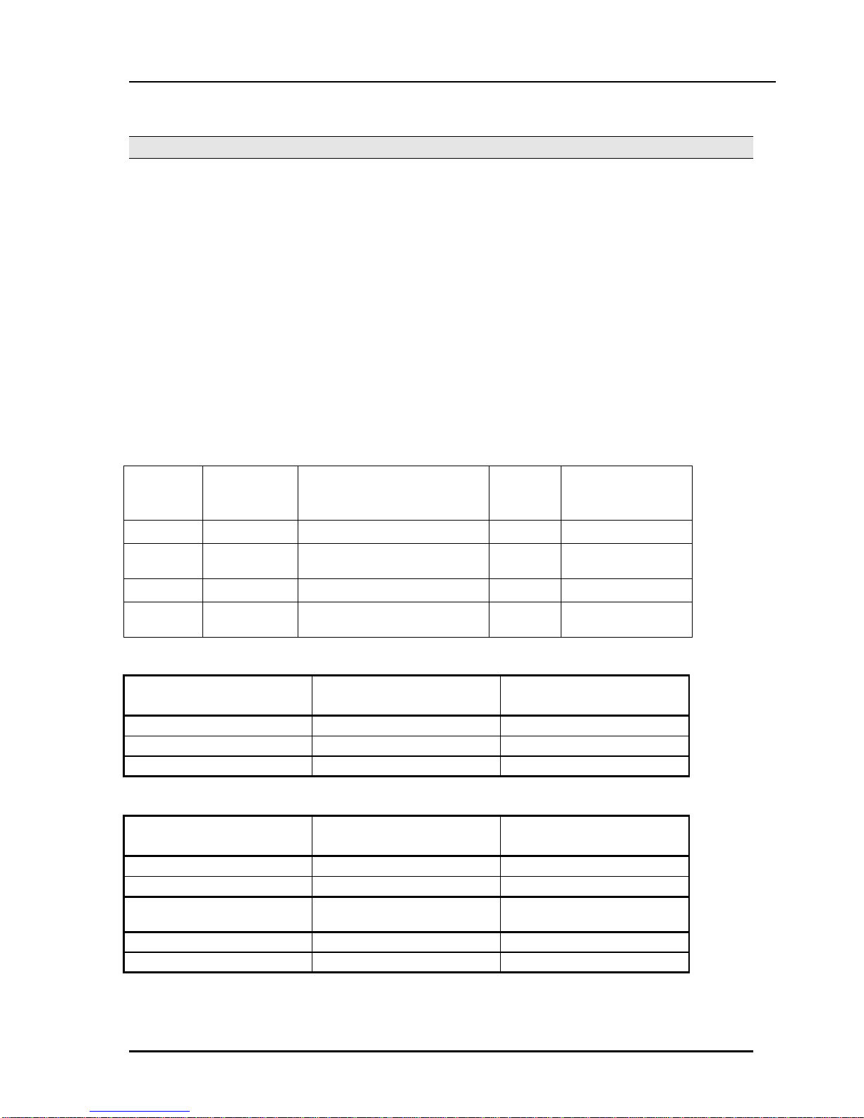
2.2.2 Aria-130 Maximum Port Capacities
When considering total port of the capacities of the system, it is necessary to consider the type of PMU
that will be installed.
The Aria-130 has four types of PMU: -
•PMU 1 & 2
•ASMU 1 & 2
PMU 1 & 2 do not support advanced features such as QSIG, PC Attendant and CTI.
ASMU 1 & 2 do support advanced features such as QSIG, PC Attendant and CTI.
PMU 1 and ASMU 1 both have a maximum of 88 ports. (Non-DECT).
PMU 2 and ASMU 2 both have a maximum of 132 ports. (Non-DECT).
So, when considering port capacities only, PMU 1 and ASMU 1 are the same and PMU 2 and ASMU 2
are the same.
PMU / ASMU summary
No of KSUs
supported
Supports Advanced
Features
(QSIG, PC Attendant, CTI)
Port
Capacity
Flash ROM size
PMU 1
1
No
88 port
4 MB ROM
ASMU 1
1
Yes
88 port
8 MB ROM + 2 MB
(SMEMU)
PMU 2
1 or 2
No
132 port
4 MB ROM
ASMU 2
1 or 2
Yes
132 port
8 MB ROM + 2 MB
(SMEMU)
Capacities without WTIB installed
PMU 1 (1 KSU only) PMU 2 (1 or 2 KSUs)
Max No. of wired stations
48
96
Max No. of CO’s
40
40
Max port capacity
88
132
Capacities with WTIB installed
PMU 1 (1 KSU) PMU 2 (1 or 2 KSUs)
Max No. of wired stations
48
96
Max No. of un-wired stations
40
80
Max No. of combined
stations
88
128 (note 1)
Max No. of CO’s
40
40
Max port capacity
128
132
Note 1 – this is the maximum number of stations possible.

Aria-130 Digital Key Telephone System Issue: 1.2
Installation Manual
15
2.2.3 System Configuration Chart
2.2.3.1 Overview
The maximum capacity of the system configured only with the wired extensions will be limited by the
physical condition of the system, e.g. the quantity of slots and cards limitation. System configuration
charts are as follows;
40 40
36
32 LCOB 8 32 LCOB
BRIB 28 SLIB II
24 KSU - 2 SLIB II 24
DTIB 12
DTIB12 20 KSU - 2
16 16
KSU - 1 12 KSU - 1
88
4
012 24 36 48 60 72 84 96 012 24 36 48 60 72 84 96
40 40 LCOB 8
BRIB
32 LCOB 32
DTIB 24
DTIB 24
24 KSU - 2 24 KSU - 2
20
16 16
12 KSU - 1 KSU - 1
8 8
4
024 48 72 96 024 48 72 96
40 PRI 40 PRI
DTIB12
DTIB 24
32 32
KSU - 2
24 24 KSU - 2
16 16
KSU - 1 KSU - 1
8 8
012 24 36 48 60 72 84 96 024 48 72 96
Figure 2.2.1 System configuration charts

Aria-130 Digital Key Telephone System Issue: 1.2
Installation Manual
16
2.3 SYSTEM SPECIFICATIONS
The following Tables provide general system specifications.
2.3.1 Dimension And Weight
Item
Height(mm/in)
Width(mm/in)
Depth(mm/in)
Weight(kg/lbs)
KSU
406
440
230.5
13.2
Digital Keyset
236/9.3
192/7.6
84/3.3
1.5/3.3
Digital DSS/DLS Console
236/9.3
125/4.9
62/2.4
0.9/2.0
Digital ICM/Door Box
45/1.8
140/5.5
100/3.9
0.5/1.1
Digital Data Module
37/1.5
175/6.9
148/5.8
1.5/3.3
Base Station(GDC-330B)
170
220
57
0.46
Wireless
GDC-33xH
145
50
35
0.15
Terminal
GDC-340H
131
49
32
0.102
Table 2.3.1 Dimension and weight
2.3.2 Environment Specification
Item Degrees ( ℃)Degrees ( ℉)
Operation Temperature
0~40
32~104
Optimum Operation Temperature
20~26
68~78
Storage Temperature
10~70
32~158
Relative Humidity
0~80% non condensing
Table 2.3.2 Environment specification
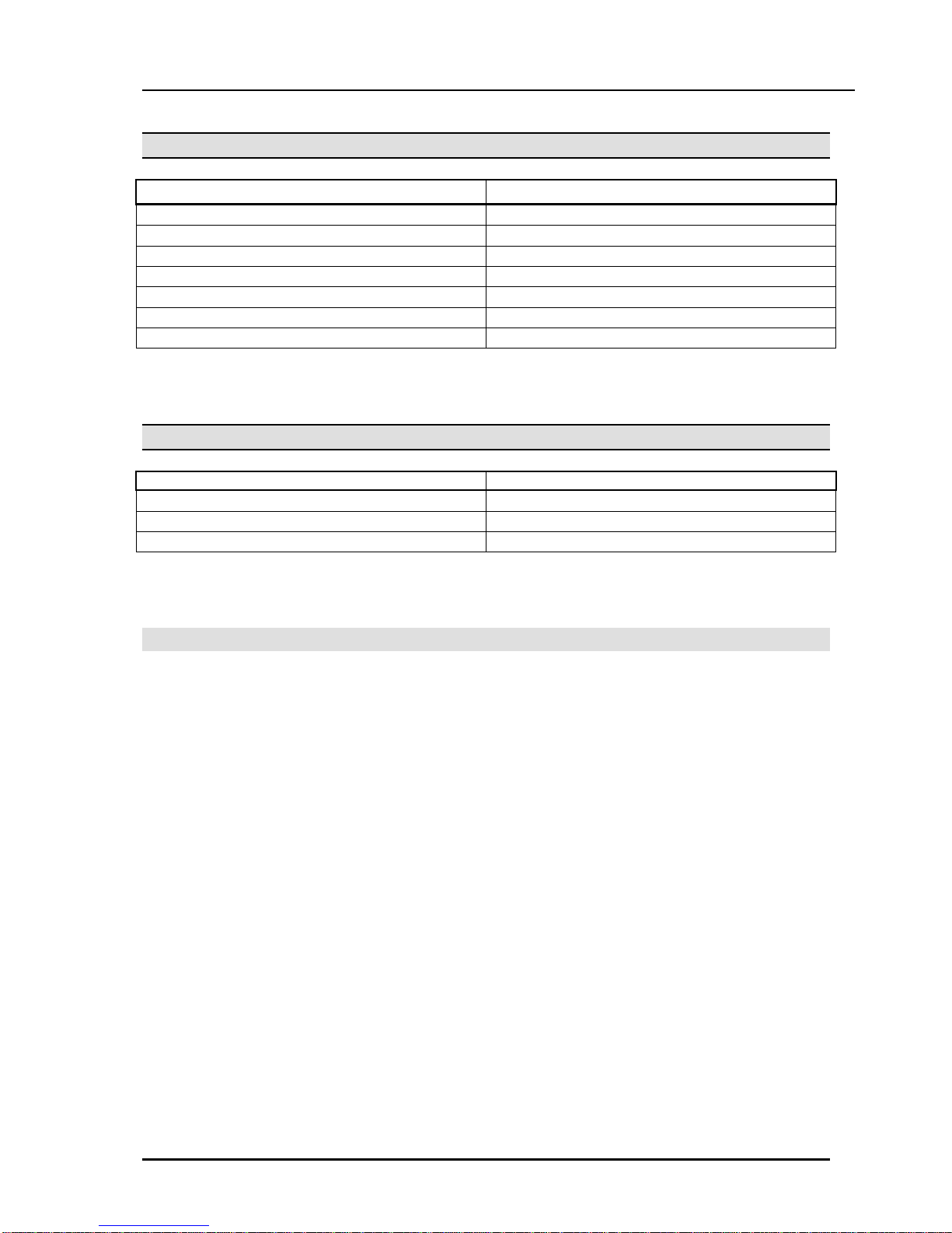
2.3.3 Electrical Specification
2.3.3.1 System Electrical Specification
Item Specification
1. PSU
- AC Voltage Input
110 or 220 +/- 10% Volt AC @48~63Hz
- AC Power
127W
- AC Input Fuse
4.0 amp @ 220Volt AC
8.0 amp @ 110Volt AC
- DC Output Voltage
+ 5, - 5, + 30Volt DC
2. Battery Backup
- PSU Input Voltage
24Volt DC
- PSU Battery Fuse
10.0amp @250Volt AC
- Charging Current
Max. 0.5A
3. External Relay Contact
1amp @24Volt DC
4. Music Source Input
0dBm @600ohm
5. External Paging Port
0dBm @600ohm
Table 2.3.3 System Electrical specification

Aria-130 Digital Key Telephone System Issue: 1.2
Installation Manual
17
2.3.3.2 Base Station Specification (GDC-330B)
Item Specification
Power feeding
+30V DC
Transmission Max Power
250mW
Access Method/Duplex
TDMA/TDD
Frequency Band
1,880 ~ 1,900MHz
Channel Spacing
1.728MHz
Modulation
GFSK
Data rate
1.152Mbps
Max. Base Station distance from the WTIB
600m (twisted 2-pair cable)
Table 2.3.4 Base Station specification
2.3.3.3 Max. Station Distance From The System
Item AWG 22 (m/kft) AWG 24 (m/kft)
Digital Keyset
DTIB12/DTIB24/DSIB
500 / 1.6
330 / 1
Single Line Telephone
SLIB24/SLIBII/SLIB2E/DSIB
2,500 / 8.2
1,600 / 5.2
SLIB48
5,000 / 16.5
3,300 / 10
Table 2.3.5 Max. Station Distance from the System
2.3.3.4 Co Loop Specification
Item Specification
Ring Detect Sensitivity
40Vrms @16~30Hz
30Vrms @30~37Hz
DTMF Dialing
Frequency Deviation
Signal Rise Time
Tone Duration, on time
Inter-digit Time
Less than +/- 1.8 %
Max. 5ms
Min. 50ms
Min. 30ms
Pulse Dialing
Pulse Rate
Break/Make Ratio
10 pps
60/40% or 66/33%
Table 2.3.6 CO loop specification
2.3.3.5 WHTU Specification
Item Specification
Max. Transmission Power
250mW
Modulation Method
GFSK
Frequency Band
1,880MHz ~ 1,900MHz
Table 2.3.7 WHTU specification
Aria-130 Digital Key Telephone System Issue: 1.2
Installation Manual
18
2.3.3.6 Specification for VOIB/VOIU
Item Specification
LAN Interface
10 / 100 Base-T Ethernet(IEEE 802.3)
Speed
10 Mbps or 100 Mbps(Auto-Negotiation)
Duplex
Half Dulpex or Full Duplex(Auto-Negotiation)
VoIP Protocol
H.323 Revision 2
Voice Compression
G.711 / G.729A / G.729B / G.723.1 / G.726 / G.727
Voice/Fax Switching
Automatic
Echo cancellation
G.168
Table 2.3.8 VOIB/VOIU Specification
2.3.3.7 Specification for LANU
Item
Specification
LAN Interface
10 / 100 Base-T Ethernet (IEEE 802.3)
Speed
10 Mbps
Duplex
Half Duplex or Full Duplex (Auto-Negotiation)
Table 2.3.9 LANU Specification

Aria-130 Digital Key Telephone System Issue: 1.2
Installation Manual
19
2.4 SYSTEM COMPONENTS
The following table shows the available slots in which every card can be installed. Some boards for GDK-
100/ARIA-300 can be used in ARIA-130 system. Others are used in only ARIA-130 system.
No
Board
Number
Slot Position
Description
Name
of Ports
1’st
KSU
2nd
KSU
1
KSU
Key Service Unit
2
PSU
PSU
PSU
Power Supply Unit, 120W
3
MPB
MPB
slot
Main Processor Board
4
PMU1
1
MPB
Program Module for only 1st KSU
5
PMU2
1
MPB
Program Module for both 1st and 2nd KSU
6
ASMU1
1
MPB
Program Module for TAPI, PC-ATTD, Networking
(support 1st KSU only)
7
ASMU2
1
MPB
Program Module for TAPI, PC-ATTD, Networking
(support 1st & 2nd KSU )
8
MODU
1
MPB
33.6Kbps Internal Modem
9
SIU
1
MPB
Serial Interface Unit
10
DMEMU
1
MPB
16Mbyte EDO-DRAM Module(S/W download)
11
LANU
1
MPB
10/100 Mbps Ethernet Interface Unit
12
MISB
6 only
Miscellaneous Board
13
DTIB12
12
1~6
1~6
Digital Terminal Interface
14
DTIB24
24
1~6
1~6
Digital Terminal Interface
15
SLIB24
6
1~6
1~6
SLT Interface(+24V Feed)
16
SLIB48
6
1~6
1~6
SLT Interface(-48V Feed), Maximum 2 cards per a
cabinet.
17
SLIBII
12
1~6
1~6
SLT Interface (-28V Feed)
18
SLIB2E
12
1~6
1~6
SLT Interface
19
DSIB
12
1~6
1~6
Digital Terminal(6) and SLT Interface (+24V Feed)
20
LCOB
4
1~6
1~6
Loop Start CO Interface
21
LCOB8
8
1~6
1~6
Loop Start CO Interface
22
ARIA-300
STIB
4 (8B)
1~6
1~6
ISDN So/To Interface (2B+D)
23
ARIA-300
BRIB
4 (8B)
1~6
1~6
ISDN Basic Rate Interface (2B+D)
24
ARIA-300
PRIB
1 (30B)
1~6
1~6
ISDN Primary Rate Interface(30B+D)
25
ARIA-130
BRIB
2 (4B)
1~6
1~6
ISDN Basic Rate Interface (2B+D)
26
ARIA-130
BRIU
2 (4B)
ARIA-130 BRIB
ISDN Basic Rate Interface (2B+D)
27
ARIA-130
PRIB
1 (30B)
1~6
1~6
ISDN Primary Rate Interface(30B+D)
28
VMIB
4
1~6
1~6
Voice Mail Interface Board
29
FMEU
4
VMIB
Flash Memory Expansion Unit (32MB)
30
VCEU
4
VMIB
Voice Channel Expansion Unit
31
WTIB
4
1~6
1~6
Wireless Terminal Interface Board
32
WTIU
4
WTIB
Wireless Terminal Interface Unit
33
EMIB
4
1~6
1~6
E&M Interface Board - India only

Aria-130 Digital Key Telephone System Issue: 1.2
Installation Manual
20
No Board Number Slot
Position Description
Name of Ports 1’st
KSU 2nd
KSU
34
VOIB
4
1~6
1~6
Voice Over Internet Protocol Interface Board
35
VOIU
2
VOIB
Voice Over internet protocol Interface Unit
36
PLLU
1
MPB
Phase Lock Loop Unit for ISDN cards
37
MSGU
6
SLIB24, DSIB
Message Waiting Unit
38
MSGU48
6
SLIB48, SLIB2E
Message Waiting Unit
39
MSGUII
12
SLIBII
Message Waiting Unit
40
DTRU
(GDK-34)
2
SLIB24,SLIB48,DS
IB LCOB
DTMF Receiver Unit
41
DTRUII
4
SLIBII
DTMF Receiver Unit
42
DTRU4
4
LCOB8,SLIB2E,SL
IBII
DTMF Receiver Unit
43
CPTU/A
2
LCOB
Call Progress Tone Detection : 305Hz~640Hz
44
CPTU4
4
LCOB8
Call Progress Tone Detection
45
CMU
(GDK-162)
1
LCOB
Call Metering Unit (16K,12PR,50PR)
46
CMU4
4
LCOB8
Call Metering Unit (12/16PR,50PR)
47
RGU6
10 SLTs
Ring Generator (25Hz) : Sine Wave, Internal
48
TERM
(GDK-162)
100 ohm Termination for BRI and STI
49
MOHU
Connected to SLT
port
External Music On Hold Unit
Table 2.4.1 System Card Description
Table of contents
Popular Telephone System manuals by other brands


NEC
NEC ELECTRA ELITE IPK II user manual

Panasonic
Panasonic KX-TD612NE Programming guide

Grandstream Networks
Grandstream Networks UCM6204 Quick installation guide

Panasonic
Panasonic KX-TSC11B Service manual

Toshiba
Toshiba Strata DK8 General description

AT&T
AT&T Merlin II Feature Module 2 Data communications guide


