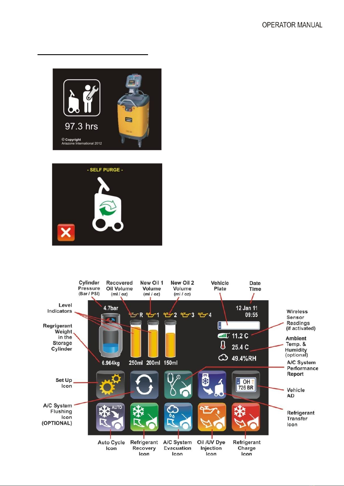
ariazone 6001 User manual

1
Ariazone 6001
HFO-1234yf
(with internal identifier)
Automotive Air-Conditioning Service Station
OPERATOR MANUAL
This equipment has been
extensively researched, designed
and developed with the prime
objective in satisfying the workshop
operator and technician in carrying
out the most efficient air-
conditioning diagnostic and service
procedure.
Please follow the proceeding
instructions carefully. If there is
anything you do not understand fully
in the proceeding text or images,
please do not hesitate to contact
your local distributor or
manufacturer.
IMPORTANT: This manual contains
important information pertinent to
operator safety, and must
accompany the unit, in the case of
sale or transfer to another party.
-----------------------------------------------------
Manufacturer reserves the right to modify
this manual and the unit itself at any time
without prior notice

2
Contents Page
1. Introduction................................................................................................................. 3
2. SAFETY FIRST! Important Safety Information's ........................................................ 4
3. Technical Specifications.............................................................................................. 5
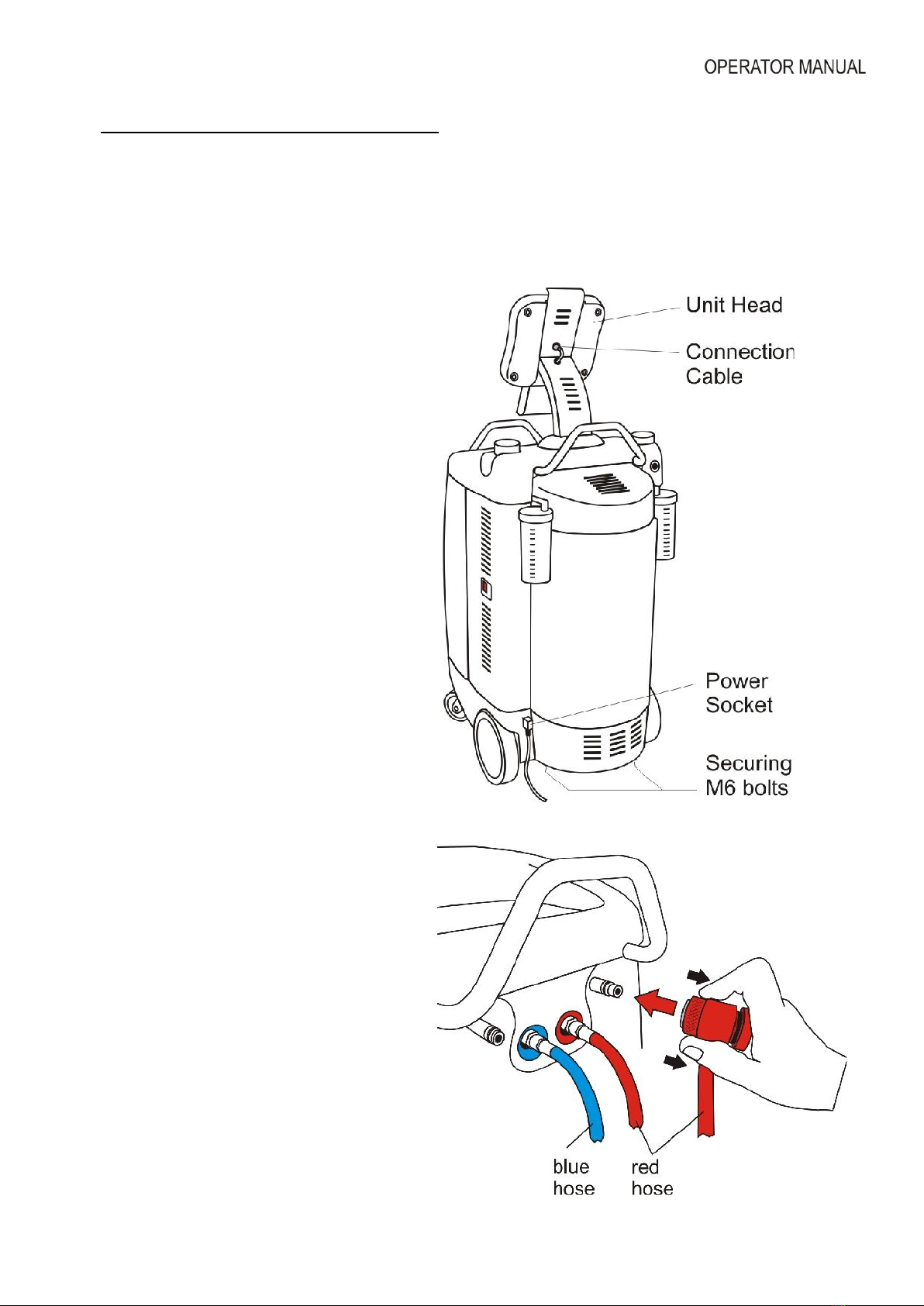
4. Preparing the Machine for the First Use ..................................................................... 6
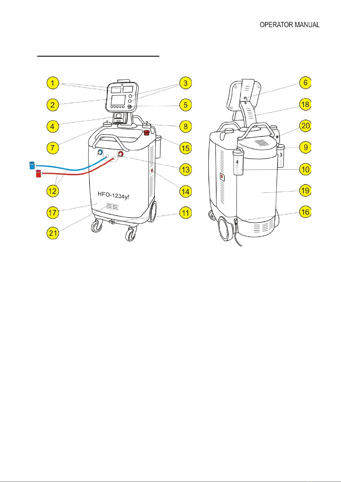
5. Main Components & Features .................................................................................... 7
6. Switching ON the Machine .......................................................................................... 9
7. Icons and their meaning .............................................................................................10
7.1. Key icons………………………………………………………………………….10
7.2 Warning icons …………………………………………………………………….12
8. Printer Set Up .............................................................................................................13
9. Storage Cylinder Filling Procedure (Refrigerant Transfer) .........................................14
10. Connecting and testing the A/C system ....................................................................17
11. Recovery & Recycling Mode .....................................................................................18
12. Evacuation Mode ...................................................................................................... 21
13. Oil & UV dye Injection Mode ..................................................................................... 23
14. Refrigerant Charge Mode ...................................................................... 25
15. Auto Mode Function ............................................................................... 27
16. Cylinder Air Purge ..................................................................................................... 29
17. A/C Flushing Mode ................................................................................................... 30
18. Settings & Optional functions ……………………………………………………………. 33
18.1. Main Unit Set up ……………………………………………………………….. 34
18.2. How to set the workshop data on print report?........................................... 35
18.3. Wireless temperature sensor Set up ………………………………………… 36
18.4. Refrigerant Management, Operation History and Working Hours Reset…. 37
18.5. Refrigerant Recycling ................................................................................. 38

3
1. Introduction
Ariazone 6001 – HFO1234yf is a user-friendly tool specifically designed for the automotive air-
conditioning technicians to carry out the following functions:
- Testing air-conditioning system
- Refrigerant identification.
-Recover and recycling the refrigerant from air-conditioning system.
-Electronically gauge amount of refrigerant recovered from air-conditioning system.
-Electronically gauge amount of oil removed from air-conditioning system (if any).
-Evacuate air-conditioning system.
-Electronically charge lubricating oil & UV dye by volume into the air-conditioning system.
-Electronically charge refrigerant into the air-conditioning system by weight.
-Electronically displays vent temperature.
-Electronically Flush A/C system (optional).
The unit is suitable for servicing passenger and light
commercial vehicles air-conditioning systems
The unit is a microprocessor control system. This provides electronically controlled functions, whilst
keeping the operator constantly informed and in full control.
This unit has been designed and build to be long lasting and with high level of reliability including
maximum safety for the operator. The operator needs only to be responsible for the correct use and
maintenance of the unit, in accordance with the instructions found in this manual.
Environmental information
This product may contain substances that can be hazardous to the
environmental or to human health if it's not disposed of properly.
Electrical and electronic equipments should never be disposed of in the
usual municipal waste, but must be separately collected for their proper
treatment (recycling).
We also recommend that you adopt appropriate measures for
environmental protection: recycling of the internal and external
packaging of the product, including batteries (if any).
With your help it is possible to protect our planet and improve the
quality of life, by preventing potentially hazardous substances being
released in to our environment.

4
2. Important Safety Information's_
This unit is simple and reliable in selecting and performing all its functions. Therefore, the user is not
exposed to any risk, if the general safety guidelines reported below are followed, in association with
proper use and maintenance of the unit (improper use and maintenance will reduce the safety of the
unit).
This equipment is to be operated by accredited technician only! Users must have basic
knowledge of air-conditioning and refrigeration systems, including potential hazards associated with
the handling of refrigerants and systems under high pressure.
Read this user manual carefully before start up, connecting and operating the
unit. If you do not understand any section of this manual, please contact your
nearest distributor or manufacturer.
Handle refrigerant with care as serious injury may occur. Always wear appropriate
protective safety gloves.
The contact with refrigerant can cause blindness. Always wear appropriate
protective safety glasses.
-Avoid inhalation of the refrigerant. Use only in well ventilated work areas.
- The power cable may only be connected to a socket with nominal voltage stated
on the rating plate, located at the rear of the unit.
- RISK OF ELECTRICAL SHOCK. Power lead plug to be connected only to power
point with an earth.
- Never operate the equipment with a damaged power lead, replace it immediately.
Before removing any protective cover from unit, always unplug power lead from
power point.
- Use only pure R134a refrigerant with this equipment.
- The unit should not be operated with flammable refrigerants (HC of R1234yf).
- Position the unit on all four wheels, on a flat (horizontal) surface so that proper
operation of the scales is guaranteed.
-Do not expose the machine to direct artificial heat or rain.
- Do not tamper with or change safety control devices or their settings.
- When (if) transporting the unit, keep upright and if possible remove refrigerant
cylinder from platform.
- Do not cover ventilation openings on chassis cover when the unit is operating.
- Maintenance is to be carried out as per the manufacturer recommendation shown
in this manual. Only original parts are to be used for maintenance and repairs.
Maintenance of the unit must only be performed by an authorized technician.
- Only non aggressive substances to be used for cleaning of the unit.

5
3. Technical Specifications
Refrigerant
HFO-1234yf
Refrigerant Identifier
R1234yf, R134, HC, Air (non-condensables), R22
Electronic scale
+/- 5g resolution
Load cell
60kg with 150% overload capacity
Display
5.7” Touch screen
LP and HP gauges
High Clarity Digital Display
Recovery cylinder
12kg
Recovery pump
Danfoss SC12G,
Recovery rate
600 g/min (liquid state)
Vacuum pump
2 stage, 100 l/min
Vacuum
3 x 10⁻¹ Pa
Dimensions
500 mm, 650mm, H-1320 mm (1000mm packed)
Weight
87 kg
Supply voltage
230VAC- 50/60Hz
Power
1800 W
Working conditions
0o to 45 oC ambient temperature, up to 100% humidity, 2000m altitude
Noise level
< 70 dB (A)
Fuse
10 amp/250V (slow blow type)
Measuring instrument
I category (Not to be mixed with II, III, IV category)
Approvals
EN 61010-1 Electric safety, EN 55014-1 EMC-CE

6
4. Preparing the Machine for Use
Perform the following steps to prepare the unit before the first use.
1. Remove the carton box and styrofoam inserts.
2. Check to ensure that all of the
accessory components are with the unit:
- Power lead
- Service hoses with quick couplers
- User's manual
- (Optional) Wireless temperature
sensor with USB cable
3. Unscrew two securing M6 bolts
situated on each side of the bottom of
the platform base.
4. Place and secure the unit head,
connect the cable (if not).
5. Connect power lead to power socket
situated behind the right hand rear
wheel, connect power lead plug to
suitable power outlet, making sure it has
an earth connection.
6. Carefully connect suction and
discharge (blue & red) service hoses to
the front M12 service ports of the
machine.
Blue hose front-left, red hose front-right.
Hook up quick couplers to parking brass
adapter (pull back bottom knurled
section with fingers and carefully press
the coupler into the proper adapter).

7
5. Main Components & Features
Note: No hand valves are incorporated on the unit. A series of electronically controlled valves are incorporated
to precisely control the functionality of the machine.
1. LP (Suction) and HP (Discharge) Digital Display - A large 80 mm x 50 mm digital displays
shows A/C suction pressures (low and high pressure). Pressure is displayed in Bar & PSI, depended
on the user selection.
2. Touch Screen 5.7” and control button – All functions icons are displayed on the LCD touch
screen. All functions are selected by touching the appropriate icon on the display. The operator is
guided step by step in setting and initiating each selected function.
3. Stop and Start Button - The stop and start button are conveniently located on the front panel to
give to the operator complete control of the equipment.
4. Printer - The thermal printer will print all results at the end of each function once completed.
5. USB to WTS charging lead - The USB port is used for downloading software and charging the
wireless temperature sensors.
6. Connecting Cable - A user friendly connecting cable is used to connect the head with IO board.
7. New Oil 1 Injection vessel - A large capacity vessel of 300ml is mounted on the left side of the
unit to electronically inject the recovered amount of oil back in to air conditioning system, or to select
the desired amount of oil to be injected.

8
8. New Oil 2 Injection vessel - A large capacity vessel of 300ml is mounted on the right side of the
unit to electronically inject the oil in to the A/C system.
9. New Oil 3 /UV dye Injection vessel (OPTIONAL) - A large capacity vessel of 250ml is mounted
on left rear side of the unit to electronically inject the oil (or UV dye) in to the A/C system.
10. New Oil 4 /UV dye Injection vessel (OPTIONAL) - A large capacity vessel of 250ml is mounted
on right rear side of the unit to electronically inject the oil (or UV dye) in to the A/C system.
11. Recovered Oil Drain Ball Valve - The unit incorporates an internal oil vessel which measures
and retains oil (if any) that is removed from A/C system during the recovery process. The operator is
prompted when the valve should be open to drain the internal vessel, when full.
12. Service hoses 2m (Suction & Discharge) with R1234yf quick connectors used to connect to the
vehicle A/C system.
13. Service Hoses Storage Ports - These ports are used to store the suction and discharge service
hoses quick couplers to avoid contaminations and damage.
14. Main Power Switch
15. Emergency Stop Button
16. Power Inlet Socket - This socket is used to connect the machine to the power supply via the
power lead.
17. Front Cover - The cover is to protect the internal components of the machine.
18. Dispaly head “neck” with adjustable angle for setting optimum working position of diplay.
19. Rear Cylinder Cover - This cover is used to protect the cylinder.
20. Air Purge Button for relasing of non-condensable (air) build up in the refrigerant cylinder.
21. Refrigerant Identificator

9
6. Switching ON the Machine
Switch ON the machine power switch.
After the welcome menu, the machine will
display the number of hours left before the
maintenance service is required.
Followed by self purge and hose evacuation
(if necessary).
This special function will prevent non-
condensable (air) to be pushed in to the
cylinder, therefore maintaining maximum
refrigerant purity.
Once this function is completed, the main menu is displayed on the LCD.

10
7.1. Key icons and their meaning
Cancel symbol
Enter
Confirm
Return, returning to previous
menu
Left arrow, back
Right arrow, scrolling right
Down arrow, scrolling down
Up arrow, scrolling up
Minus (Decrease)
Plus (Increase)
Delete all
Edit
Symbols
Print the report
Unit set up
Basic settings
Advanced settings
Wireless sensors activation
Optional functions
activation
Factory settings
Refrigerant identifier
Refrigerant recycling
Refrigerant Management
100 Working hours reset
Refrigerant Management
Reset
300 Working hours reset

11
Refrigerant transfer
function
Set refrigerant weight
Full transfer (transferring the
entire amount of refrigerant
from the cylinder)
Change service hose selection
Recovery function
Full recovery (removing the
entire refrigerant from the air-
con system)
Open flow only on discharge -
High Pressure service hose
Open flow on both service
hoses Low and High Pressure
Full Automatic
Function
Open flow only on suction -
Low Pressure service hose
Change the vacuum time
Change the amount of oil
Leak detection under vacuum
set up
Change the charge weight
Set the new oil amount
Set the UV Dye amount
Evacuating, removing air and
moisture from within the air-
conditioning system
Set time
New oil and/or UV Dye
Injection function
Set amount of oil to be injected
in the system
Refrigerant charge function
Select charge amount from
Database
Select manufacturer of the
vehicle
Select vehicle engine
Select vehicle production year
Vehicle AD

12
7.2. Warning icons and their meaning
Refrigerant in the a/c
system, machine will
not start evacuate
process. Automatically
will start Recovery.
No refrigerant in the a/c
system, machine will not
start Recovery process.
Refrigerant cylinder on
machine is empty.
Refrigerant cylinder on
machine is full.
Recovered oil vessel
full. Drain the oil from
the vessel.
Oil vessel empty. Fill new
oil in the vessel.
No refrigerant in the
storage cylinder,
machine will not start
transfer process.
The machine has stopped
due to excessive high
working pressure.
Leak test under vacuum
failed. A/C system
leaking or loose
connection
Micro leak test under
vacuum failed. A/C system
is leaking or loose
connections.
No enough vacuum in
the a/c system.
Oil injection aborted. No
vacuum in the A/C system.
Contact your distributor
for activation of
selected function.
Quick coupler is blocked.
Check the connection.
Machine requires 100
working hours service.
Machine requires 300
working hours service.
Updating software.
Updating database.

13
8. Printer Set Up
The printer is equipped with two keys and green led:
>> Paper feed
II on line / off line
The green led shows the state of the printer:
- Led constantly ON - Printer in line
- Led blinking - Printer not in line or no paper
- Led off - Press II. If the problem persists, contact authorized distributor or manufacturer.
Printer roll specifications,
Paper width: 57-58mm
Max paper thickness: 80 µ
Printer report:

14
9. Storage Cylinder Filling Procedure (Refrigerant Transfer)
The purpose of the Refrigerant Transfer mode is to transfer new refrigerant from a
storage cylinder into the machine cylinder.
Note: The machine refrigerant cylinder which is situated behind the cylinder cover is supplied empty
of refrigerant. The cylinder is evacuated by the manufacturer.
Keep the new refrigerant cylinder sitting upright connect the suction (blue) service hose to new
refrigerant cylinder liquid valve by using the brass adapter provided. Open liquid valve on storage
cylinder and open suction service hose quick coupling.
Select Transfer function (by touchhing refrigerant Transfer
icon).
The display shows last used selection.
By pressing button switch Identifier icon - ON/OFF.
To change hose selection (only if it’s wrong),
touch Compressor icon and…

15
There are 2 options when transfering refrigerant:
1. To select weight to be transfered, touch the Weight icon
and by using the keypad select desired…
... amount of refrigerant (in gr) to be transferred
into the machine cylinder and touch Confirm icon.
2. To transfer the complete amount of refrigerant from the
new refrigerant cylinder in to the machine cylinder,
Finally to start Transfer f-tion touch Confirm icon
If is ON, identifier will enter in calibraton mode.
NOTE: Machine must be in vacuum.
When calibration is finished, display will show again the
start screen.
By turning clockwice open the blue (LP) quick
coupler and press START button.
If results are good will be printed and the machine will
continue with transfer process.
If results are not good will be printed and the
machine will abort transfer process. Press STOP
button to go back in main screen.

16
Before transfer process start, the machine will self purge
(if required).
During the transfer process the machine will display the
amount of refrigerant being recovered.
This process can be paused by pressing Stop button and
abort the function totally by pressing the Stop button again
or restart the process by pressing the Start button.
Once the machine has reached a vacuum of -0.25 kPa it
will enter into recovery pause for duration of 2 minutes to
allow for any remaining refrigerant in the cylinder and
hoses (if any) to boil off.
.
If after the 2 min. pause there is no further pressure
increase in the A/C system the machine will drain and
measure the recovered oil (if any).
The display will show the total amount of refrigerant
transferred and oil (if any).
This will be displayed until the stop button is depressed
which then machine will display main menu again ready to
select another function if required.

17
10. Connecting and testing the A/C system
Use the service hose quick couplers to connect the hoses to the A/C system service ports, bearing in mind that
BLUE must be connected to the low-pressure (suction) side and RED to high pressure (discharge) side.
Important: Before connecting the quick couplers, clean the a/c ports of any foreign material (grease
or dust).
Winding the hand wheel quick couplers clockwise will allow the refrigerant to flow through the hoses. Turning
hand wheel in opposite direction, the flow will be closed. If there is any refrigerant in the air-conditioning
system, the pressure displays will indicate pressure.
The unit digital displays (suction & discharge) are important and important instruments.
The digital displays indicate the working pressure of the suction and the discharge side of the A/C system. The
pressures are displayed in Metric or Imperial system depended of the user selection.
The operator should have basic understanding between gauge reading and air-conditioning system normal
operating pressures, in order to correctly diagnose any possible system malfunction.
Above the digital displays is a bar graph which gives an estimation of good, fair or bad working pressures of the
A/C system. The black segment on the bar graph is related with the working pressure readings. The bar graph
colour coding is only indication.

18
11. Recovery & Recycling Mode
The purpose of the Recovery & Recycling mode is to recover refrigerant from the
air conditioning system, which will condense, purify and store the liquid refrigerant
in the unit cylinder ready for re-use.
To select Recovery function, touch the Recovery icon.
The display shows last used selection (usually
operator just confirms 100% selection).
By pressing button switch Identifier icon - ON/OFF.
To change (if needed) service port (hose) selection,
touch Compressor icon and…
… select the desired A/C service port or both
ports. Recovery process is faster when both
suction and discharge ports are selected.
To recovery desired quantity of refrigerant from A/C
system, touch Weigh icon and…
… and select the desired amount of refrigerant to
be recovered. Touch Enter icon.
When selection is finished touch Confirm icon and …
If is ON, identifier will enter in calibraton mode.
NOTE: Machine must be in vacuum.
When calibration is finished, display will show
again the start screen.

19
… press the start button to start the recovery process
NOTE: Machine will NOT START if there is no
pressure in the hoses.
While analyzing, display will show:
If results are good will be printed and the machine will
continue with Recovery process.
If results are not good machine will abort
Recovery process. Press STOP button to go back
in main screen.
Before recovery process starts, the machine will self
clean the residual refrigerant inside (if any).
During the recovery process the machine will display the
amount of refrigerant being recovered.
Recovery process can be paused by pressing Stop
button and abort the function totally by pressing the
Stop button again or restart the process by pressing the
Start button.

20
Once the machine has reached a vacuum of -25 kPa it
will enter into recovery pause for duration of 2 minutes
to allow for any remaining refrigerant in the A/C system
(if any) to boil off.
If the pressure in the A/C system increases above 0 kPa
the machine will automatically return in to recovery re-
run to the remove the rest of the refrigerant which has
boiled off in the A/C system.
If recovery re-run is initiated again the machine will pull
down to a further vacuum of -30 kPa and then it will
pause again for a further 2 minutes.
After the 2 minutes of pause if there is no further
pressure increase in the A/C system the machine will
drain and measure the recovered oil from recovered
refrigerant (if any).
Once the selected function has been completed
successfully the display will show the total amount of
refrigerant and oil (if any) recovered form the a/c
system.
This will be displayed until the stop button is depressed
which then machine will display main menu again ready
to select another function if required.
Printer will automatically print the report.
This manual suits for next models
1
Table of contents
Popular Automobile Accessories manuals by other brands

RBO
RBO RBO8042 product manual

Dobinsons
Dobinsons BU19-3542 installation guide

Stark
Stark 650LB Owner's manual and safety instructions

Alexo Sweden
Alexo Sweden E13 00-2286 Installation and operating instructions

Larson Electronics
Larson Electronics ACRO Lights X930-W manual

Prorack
Prorack K631 Fitting instructions