Ariens 79217100 User manual

Instruction Sheet
Kit Number: 79217100
Copyright 2017 • Ariens Company • Brillion, WI 54110 08400384A • 2/17 • Page 1 of 11
POWERED DECK LIFT KIT
PACKAGE CONTENTS
Check the contents of your kit for the parts listed below.
Also see Figure 1.
PROCEDURE
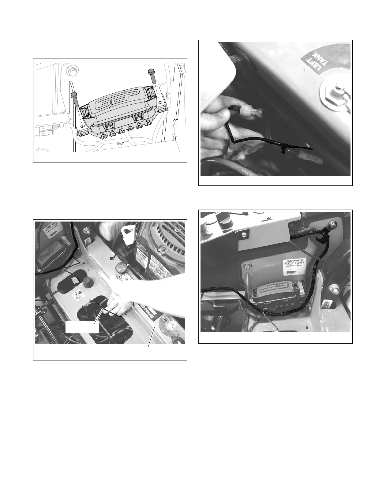
1. Place unit in service position and disconnect
negative battery cable.
2. Return seat to operating position.
3. Place transport lock lever in the forward position
and raise the deck to the transport position.
4. Position supports such as wood blocks or jack
stands under deck.
WARNING: FAILURE TO FOLLOW
INSTRUCTIONS could result in personal injury
and/or damage to unit.
Read, understand, and follow all safety practices
in Operator’s Manual before beginning.
Item Description Qty Ariens P/N
1. Actuator Mounting Bracket 1 05108551
2. Mounting Pin 2 04385700
3. 1/2-13" Center Locking Nut 1 06536300
4. Actuator 1 04411500
5. 1/2-13 x 2 1/4" Hex Bolt 1 05961000
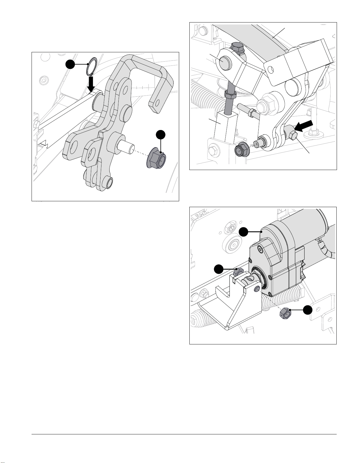
6. Actuator Pin 1 05109000
7. 1/2" Retaining Ring 1 05717100
8. J-Clamp 3 06909400
9. Wire Harness 1 04458900
10. Switch Mounting Bracket 1 05108951
11. Actuator Switch 1 00652100
12. 3/8-16 x 2 3/4" Hex Bolt 2 05961400
13. 3/8-16" Center Locking
Flange Nut 2 06534800
14. Pinch Point Safety Decal 2 05359400
15. 3/4-10" Nyloc Locking
Flange Nut 1 06500717
16. 1 1/4" Retaining Ring 2 05700213
17. Deck Lift Arm 1 05108667
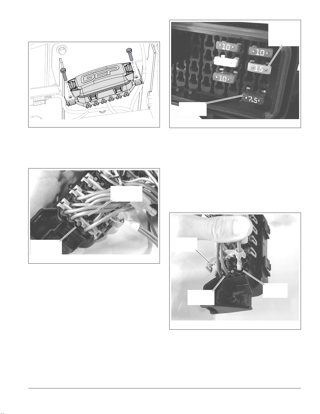
18. 20-Amp Fuse 1 04438300
19. 1/4-20" Nyloc Locking
Flange Nut 1 06500012
20. 1/4-20 x 1/2" Hex Bolt 1 05947900
WARNING: Disconnect battery prior to installing
kit.
WARNING: AVOIDINJURY.Mowerlift armsand
mower lift pedal could cause severe injury if the
lift assist spring is not disconnected before
disconnecting the lift links.
Springs store energy. Keep body parts well away
from pinch points when removing the deck.
05359400A
Figure 1
8
15
18
9
4
10
2
11
1
17
6
12
13
7
14
35
16
20
19

08400384A • 2/17 • Page 2 of 11
5. Loosen jam nuts against spring plugs and turn
spring plugs clockwise to remove from spring adjust
bolt. See Figure 2.
6. Release transport lock and lower deck onto
supports.
See Figure 3.
7. Remove retaining ring from clevis pin and remove
clevis pin. Retain parts.
8. Loosen jam nut against deck lift link and remove
hex bolt from lift link.
9. Remove jam nut from hex bolt and remove hex bolt
from deck lift pin. Retain parts.
See Figure 4.
10. Remove and retain deck lift pin.
11. Rotate connecting arm away from deck lift arm.
12. Remove flange nut retaining deck lift arm.
See Figure 5.
13. Reinstall flange nut removed in step 12 onto deck
lift shaft and finger tighten until nut stops.
IMPORTANT: Deck lift shaft is tapered and will require
impact from a sledgehammer to remove deck lift arm.
14. Strike flange nut on shaft end with a sledgehammer
to disengage key in deck lift shaft from deck lift arm.
NOTICE: Strike flange nut squarely, but DO NOT use
excessive force. Excessive force may drive key into
flange bushing, resulting in damage.
Figure 2
Spring Plug
Spring Bolt
Trunnion
Figure 3
Jam Nut
Clevis Pin
Figure 4
Deck Lift Pin
Flange Nut
Connecting
Arm
Figure 5
Key Flange
Bushing
Deck Lift
Shaft
Flange Nut

08400384A • 2/17 • Page 3 of 11
See Figure 6.
15. Remove flange nut from deck lift shaft and discard.
16. Remove interior retaining ring from deck lift arm and
discard.
17. Remove deck lift arm.
See Figure 7.
18. Remove Woodruff key from deck lift shaft.
19. Remove any rust from shaft with sandpaper.
20. Apply a thin layer of anti-seize compound to deck lift
shaft.
21. Reinstall Woodruff key.
22. Position trunnion on deck lift arm assembly in a vice
and remove nut from trunnion. Retain parts. See
Figure 8.
23. Remove hardware retaining height-of-cut mounting
pins and remove pins. Discard parts. See Figure 9.
Figure 6
Figure 7
Woodruff Key
Figure 8
Trunnion Nut Trunnion Spring
Adjust
Bolt
Figure 9

08400384A • 2/17 • Page 4 of 11
See Figure 10.
24. Remove and retain two hex bolts and two locking
washers from height-of-cut dial bracket.
25. Secure two J-clamps (item 8) to height-of-cut dial
bracket with hardware removed in previous step.
See Figure 11.
26. Remove and retain lower rear pivot bracket
mounting screw.
27. Secure one J-clamp (item 8) to pivot bracket with
hardware removed in previous step.
See Figure 12.
28. Install mounting pins (item 2) through height-of-cut
dial bracket.
29. Install actuator mounting bracket (item 1) onto
mounting pins.
30. Secure mounting pins and mounting bracket with
two 3/8 x 2 3/4" hex bolts (item 12) and two 3/8"
center locking flange nuts (item 13).
See Figure 13.
31. Install one 1 1/4" retaining ring (item 16) onto deck
lift arm (item 17).
32. Install deck lift arm onto deck lift shaft and through
height-of-cut mounting arm.
Figure 10
8
8
Figure 11
8
Pivot
Bracket
Fender
Figure 12
113
12
2
Figure 13
16
17
Deck Lift
Shaft
Height-of-Cut
Mounting Arm

08400384A • 2/17 • Page 5 of 11
33. Secure deck lift arm with one 3/4" nyloc locking
flange nut (item 15) and one 1 1/4" retaining ring
(item 16). Torque flange nut to 176.3 – 203.4 N•m
(130 – 150 lb-ft). See Figure 14.
See Figure 15.
34. Reposition connecting arm into deck lift arm.
35. Secure trunnion and spring adjust bolt to deck lift
arm with original flange nut.
36. Reinstall deck lift pin through deck lift arm.
37. Reinstall hardware through deck lift pin and into
deck lift link. Tighten jam nut against deck lift link.
38. Level deck. Refer to Operator’s Manual for
instructions.
39. Position actuator (item 4) in actuator mounting
bracket and secure with one 1/2 x 2 1/4" hex bolt
(item 5) and 1/2" center locking nut (item 3). See
Figure 16.
Figure 14
16
15
Figure 15
Connecting
Arm
DeckLift
Pin
Deck Lift
Link
Spring
Adjust Bolt
Figure 16
4
5
3

08400384A • 2/17 • Page 6 of 11
40. Align connecting arm and actuator piston with deck
lift arm and insert actuator pin (item 6) through
holes. Secure with one 1/2" retaining ring (item 7).
See Figure 17.
NOTICE: NEVER secure wires to fuel lines, positive (+)
battery cables, moving parts, surfaces that become hot
during operation, sharp edges or pinch points.
41. Disconnect ground wire from battery.
42. Route actuator wire back and into front J-clamp.
Bend J-clamp closed with a pliers. See Figure 18.
43. Rotate seat forward.
See Figure 19.
44. Connect wire harness (item 9) to actuator wire.
45. Route wire harness through J-clamps on
height-of-cut bracket and pivot bracket. Bend
clamps closed with a pliers.
46. Route wire harness under fender and behind seat.
47. Remove and retain control panel hardware, but DO
NOT remove control panel. See Figure 20.
Figure 17
6
7
Connecting
Arm
Figure 18
Figure 19
9
Fender
Figure 20

08400384A • 2/17 • Page 7 of 11
For certain units, it may be necessary to drill a hole in the
side of the control panel. If control panel already has a
hole, advance to step 49.
48. Position switch mounting bracket (item 10) over
control panel and mark location that aligns with side
mounting point. See Figure 21.
See Figure 22.
49. Install actuator switch (item 11) in switch mounting
bracket.
IMPORTANT: Switch MUST be positioned so the square
notch faces the front of switch mounting bracket.
See Figure 23.
50. Drill a 1/4" hole through mark on control panel.
51. Connect wire harness to actuator switch.
See Figure 24.
52. Secure switch mounting bracket to control panel
with original control panel hardware, one 1/4 x 1/2"
hex bolt (item 20) and one 1/4" nyloc locking flange
nut (item 19).
53. Secure control panel with remaining original
hardware.
Figure 21
Mark Here
10
Figure 22
11
Square
Notch
Figure 23
Figure 24
19
20
Original Hardware

08400384A • 2/17 • Page 8 of 11
54. Remove fuse block cover.
55. Remove and retain fuse block hardware. See
Figure 25.
56. Turn fuse block upside-down.
If the number 6 and the number 2 fuse block ports are
open, continue to step 57. If the number 6 port has power
supply (purple wire) and the number 2 port is open,
advance to step 65. See Figure 26.
See Figure 27.
IMPORTANT: Enabling the powered deck lift kit requires
disabling either the 12V power port or the auxiliary port
for the headlight kit.
57. Remove either the 7.5-amp or the 15-amp fuse.
Retain for future reinstallation.
• Removing the 7.5-amp fuse disables the 12V
power port.
• Removing the 15-amp fuse disables the auxiliary
port for the headlight kit.
See Figure 28.
58. Remove and retain blue wire retainer.
NOTICE: Wire ends are Delphi Metri-Pack 280 Series.
Use the correct tool to remove wire from fuse block port
in following step.
59. Remove the purple wire from the port of the
disabled feature.
• If the 7.5-amp fuse was removed, remove the
purple wire from the number 1 fuse block port.
• If the 15-amp fuse was removed, remove the
purple wire from the number 3 fuse block port.
Figure 25
Figure 26
Number 2
Port (Open)
Number 6
Port (Open)
Figure 27
12V Power
Port Fuse
Auxiliary for
Headlight
Kit Fuse
Figure 28
Number1
Port
Number3
Port
Blue Wire
Retainer

08400384A • 2/17 • Page 9 of 11
See Figure 29.
60. Insert purple wire from wire harness (item 9) into
either the number 1 or 3 port, whichever is open.
61. Gently tug on wire to ensure it is correctly seated
and secure.
62. Reinstall blue wire retainer.
See Figure 30.
63. Install 20-amp fuse (item 18) into block where fuse
was removed from in step 59.
• Install fuse into ports 1 and 5 if the 7.5-amp fuse
was removed.
• Install fuse into ports 3 and 7 if the 15-amp fuse
was removed.
64. Advance to step 71.
See Figure 31.
65. Remove and retain blue wire retainer.
66. Remove and discard green plug from the number 2
fuse block port.
67. Insert purple wire from wire harness (item 9) into
the number 2 fuse block port.
68. Gently tug on wire to ensure it is correctly seated
and secure.
69. Reinstall blue wire retainer.
70. Install the 20-amp fuse (item 18) into fuse block
ports 2 and 6. See Figure 32.
Figure 29
9
Number1
Port
Number3
Port
Figure 30
18
Port 1
Port 5
Port 7
Port 3
Figure 31
Number2
Port
9
Blue Wire
Retainer
Figure 32
18
Port 2
Port 6

08400384A • 2/17 • Page 10 of 11
See Figure 33.
71. Reinstall fuse block and secure with original
hardware.
72. Reinstall fuse block cover.
See Figure 34.
73. Route ground (black) wire from wire harness under
frame and through frame channel.
NOTICE: Route wire so that it will not contact belts or
other moving parts. Use a cable tie to secure wire, if
necessary.
74. Connect black wire to auxiliary ports located near
left hydraulic oil reservoir. See Figure 35.
75. Route wire harness below fuse block, into J-clamp
and under control panel. See Figure 36.
76. Reconnect ground wire to battery.
Figure 33
Figure 34
Black Wire
Frame Channel
Figure 35
Figure 36

08400384A • 2/17 • Page 11 of 11
77. Adhere pinch point safety decals (item 14) to front
deck lift arm and frame. See Figure 37.
78. Reconnect negative battery cable to terminal and
return seat to operating position.
79. Raise deck to highest cutting height.
80. Turn jam nut on spring bolt 2" away from trunnion
and thread bolt into spring plug. Tighten bolt until
spring plug contacts jam nut, then turn jam nut
against spring plug. See Figure 38.
OPERATION
IMPORTANT: Ignition key must be in the "Run" position
to operate deck lift.
1. Push the front of the deck lift switch to raise mower
deck.
2. Select cutting height on height-of-cut dial.
3. Position transport lock lever in the rear position to
disengage transport lock.
4. Push the rear of the deck lift switch to lower deck to
selected cutting height.
Figure 37
14
14
Figure 38
Spring
Plug Jam Nut
Table of contents
Other Ariens Lawn Mower Accessories manuals

Ariens
Ariens G422SL User manual

Ariens
Ariens 891003 Owner's manual

Ariens
Ariens Gravely IKON-X User manual

Ariens
Ariens 53611500 User manual

Ariens
Ariens SNO-THRO 72103300 User manual

Ariens
Ariens 815046 User manual

Ariens
Ariens 79401300 User manual

Ariens
Ariens GRAVELY Zoom & ZT Bagger User manual

Ariens
Ariens 891008 User manual

Ariens
Ariens EZRider 815005 Owner's manual