Ariens SNO-THRO 72103300 User manual

Questions, problems, missing parts? Before returning to your retailer, call
customer service at 1-800-854-2315, 8a.m. - 4p.m., PST, Monday-Friday.
Email: customerservice@classicaccessories.com
WARNING
17cH55_30999
READ YOUR INSTRUCTIONS COMPLETELY AND CAREFULLY BEFORE ATTEMPTING TO SET UP YOUR
CAB OR OPERATE YOUR SNOW THROWER WITH YOUR NEW CAB INSTALLED.
Ariens Sno-Thro and Ariens are registered trademarks of the Ariens Company.
SNO -THRO
®
CAB KIT
ITEM/ARTICLE: 72103300
English (page 01)
Français (page 13)

2
TABLE OF CONTENTS
Safety Information................................................................................................................................................................................... 2
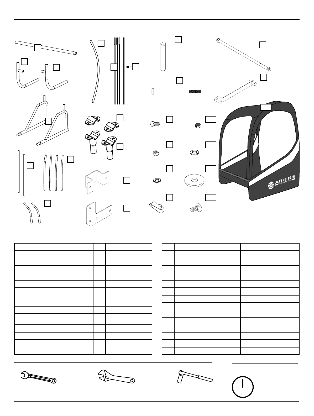
Package Contents List (Parts and Hardware)............................................................................................................................................ 3
Tools Needed ........................................................................................................................................................................................... 3
Assembly Time......................................................................................................................................................................................... 3
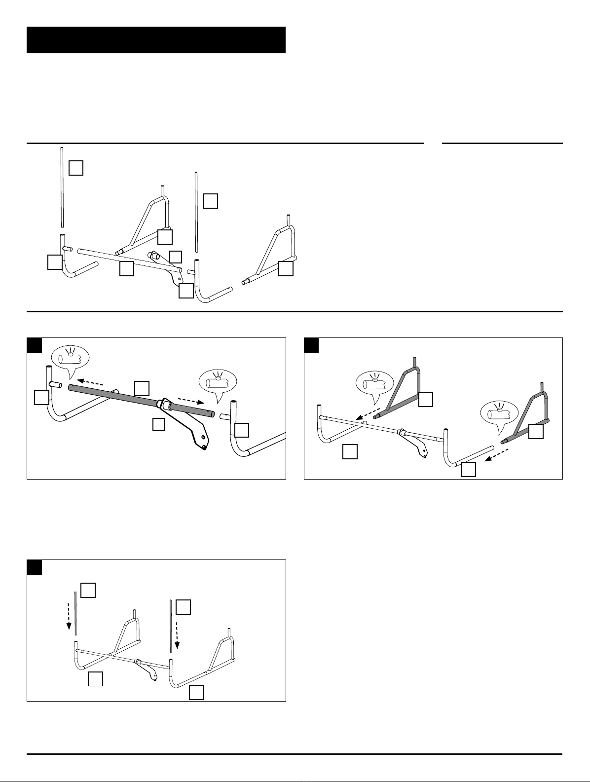
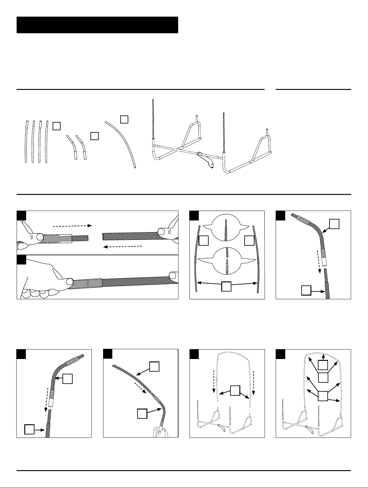
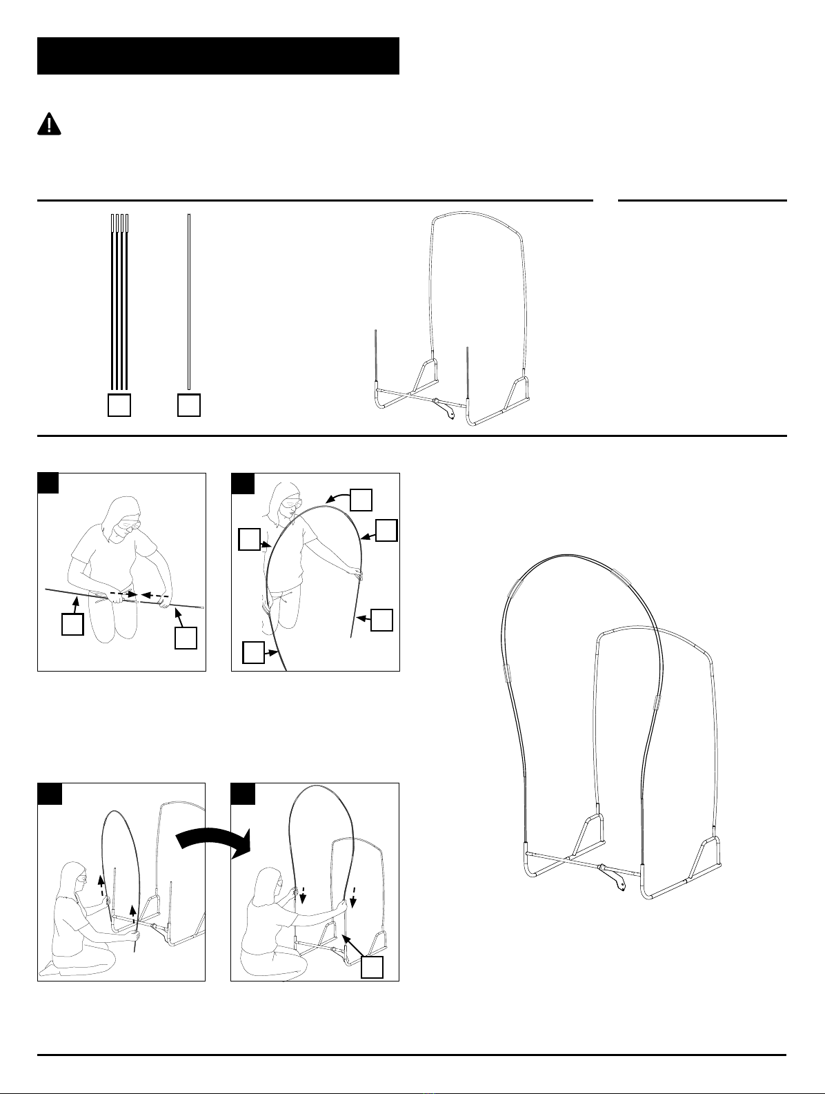
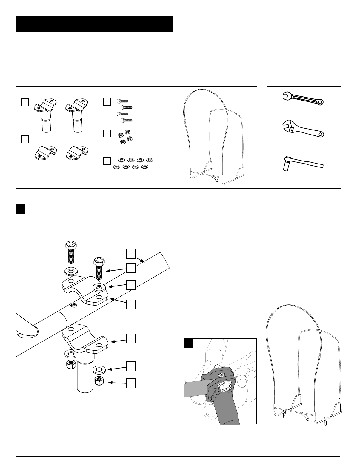
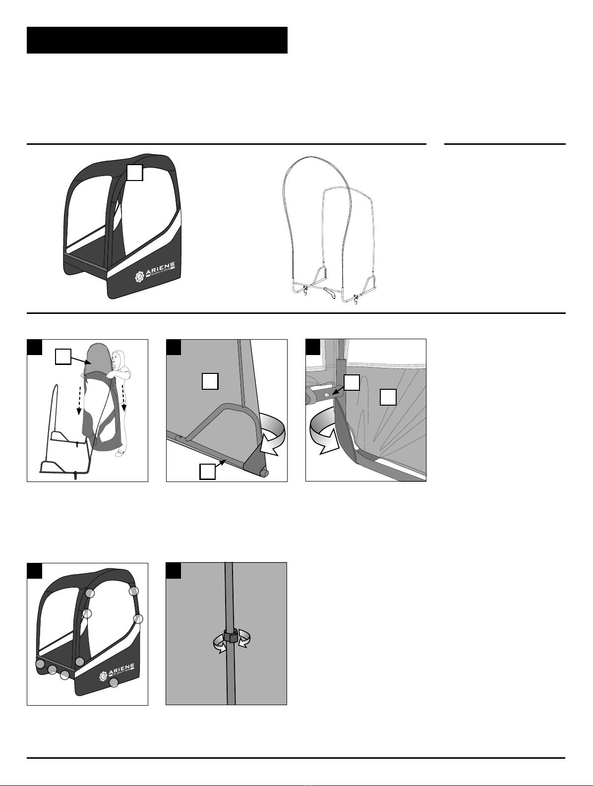
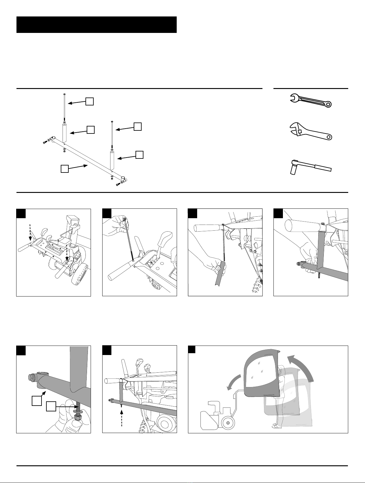
Assembly Instructions ......................................................................................................................................................................... 4-11
Care and Maintenance.............................................................................................................................................................................12
Troubleshooting......................................................................................................................................................................................12
Warranty.................................................................................................................................................................................................12
Replacement Parts..................................................................................................................................................................................12
SAFETY INFORMATION
Please read and understand this entire manual before
attempting to assemble, operate or install the product. If
you have any questions regarding the product please call
Classic Accessories customer service at 1-800-854-2315,
8a.m. - 4p.m., PST, Monday-Friday.
1. THE CAB IS NOT A PROTECTIVE DEVICE.
The cab will NOT protect against noise, engine exhaust,
chemicals, collision, roll-over or other accidents.
2.Follow all of your snow thrower manufacturer’s
recommended safety instructions.
3.Operating a snow thrower with this cab will restrict
your field of vision. Watch carefully for people, children,
obstructions or obstacles.
4.The cab adds height to your snow thrower. Remember
the height of your cab. Watch carefully for tree limbs or
other items overhead that you could previously go under
without a cab.
5.Before use, be sure that all bolts are tight. If one or more
bolts comes loose, failure of cab parts may occur.
PRACTICE SAFE MAINTENANCE
• Only qualified, trained adults should service this machine.
• Understand service procedure before doing work.
• Keep area clean and dry.
• Do not operate the engine in a confined space where
dangerous carbon monoxide fumes can collect.
• Never lubricate, service or adjust the machine or
attachment while it is moving. Keep safety devices in
place and in working condition.
• Keep hardware tight.
• Keep hands, feet, clothing, jewelry, and long hair away
from any moving parts to prevent them from getting
caught.
• Disconnect battery or remove spark plug wire (for gasoline
engines) before making any repairs.
• Keep all parts in good condition and properly installed.
Fix damage immediately. Replace worn or broken parts.
Replace all worn or damaged safety and instruction
decals.
• Check all hardware at frequent intervals to be sure the
equipment is in safe working condition.
• Do not modify machine or safety devices. Unauthorized
modifications to the machine or attachment may impair its
function and safety.
WEAR APPROPRIATE CLOTHING
• Always wear eye protection when operating the machine.
• Wear close-fitting clothing and safety equipment
appropriate for the job.
• Always wear substantial footwear and long trousers.
• Wear a suitable ear protective device such as earplugs.
• Loud noise can cause impairment or loss of hearing.

3
PACKAGE CONTENTS LIST (PARTS)
START ASSEMBLY ON PAGE 4
TOOLS NEEDED
OROR
ASSEMBLY TIME
One Hour (60 Minutes)
AHV
X
K
E
D
F
Z
Q
R
S
T
U
W
IJ
G
Part Description Qty. Part No.
ACenter Mounting Bar 1PRT-72102600-A
BRight Mounting Bar 1PRT-72102600-B
CLeft Mounting Bar 1PRT-72102600-C
DMounting Bar Ends 2PRT-72102600-D
EFront Poles 2PRT-72102600-E
FBack Hoop Side Poles
(2with PVC ends)
4PRT-72102600-F
GBack Hoop Corner Poles 2PRT-72102600-G
HBack Hoop Top Pole 1PRT-72102600-H
IFront Hoop Side Poles - Black
(with PVC ends)
4PRT-72102600-I
JFront Hoop Top Pole - White 1PRT-72102600-J
KMounting Post, Upper Clamps 2PRT-72103300-K
LMounting Post, Upper Plates 2PRT-72102600-L
XSquare Tube Hat Bracket 1PRT-72103300-X
Part Description Qty. Part No.
YSquare Tube Flat Bracket 1PRT-72103300-Y
VMounting Bracket Spacer 2PRT-72103300-V
ZHex Bolts 1/4" - 20 x 8.25"2PRT-72103300-PTKT
QHex Bolts 5/16" - 18 x 1.25"6PRT-72103300-PTKT
RNylock Nuts 5/16"8PRT-72103300-PTKT
SWashers 5/16"12 PRT-72103300-PTKT
TSpring Pins (4installed | 2extra) 6PRT-72103300-PTKT
UMounting Bracket 1PRT-72103300-U
EE Cab Fabric Shell 1PRT-72103300-EE
WSupport Brace 1PRT-72103300-W
AA Nylock Nuts 1/4"2PRT-72103300-PTKT
BB Washers 1/4"4PRT-72103300-PTKT
CC Fender Washer 5/16"2PRT-72103300-PTKT
DD Carriage Bolt 5/16" - 18 x .75"4PRT-72103300-PTKT
B
C
L
SPRING CLIP
INSTALLED AT FACTORY
KNOB WITH M8 STUD
4MM ALLEN WRENCH
M8 X 30 HEX BOLT
M8 WASHER
Y
AA
Z
DD
FOR SQUARE TUBE HANDLE BAR SYSTEM
BB
CC
EE
1/2in. Box Wrench &
7/16 in. Box Wrench
Adjustable Wrench 1/2in. Socket Wrench &
7/16 in. Socket Wrench

4
PARTS NEEDED TOOLS NEEDED
B
C
E
E
Insert the front poles [E] onto the upright ends of the side mounting bars [B, C].
6
A
A
B
B
B
C
C
C
D
D
D
D
E
E
Slide the support brace [W] onto the center mounting bar [A].
Insert the center mounting bar [A] onto the stub tube of the
right mounting bar [B] until the spring button pops through
hole in center bar. Repeat with left mounting bar [C].
Slide the mounting bar end [D] onto the end of the right mounting bar [B].
Making sure the spring button on the mounting bar end [D] pops into the
hole on the side mounting bar [B]. Repeat with opposite mounting bar [D].
1
3
2
ASSEMBLE THE FRAME (FIG. 1-3)
Note: Assemble frame on a clean flat surface next to your snow thrower for easy mounting.
STEP 1
NONE
W
W

5
PARTS NEEDED TOOLS NEEDED
ASSEMBLE THE BACK HOOP FRAME (FIG. 1-6)
Note: It may help to place the parts on a flat surface for easier assembly.
Note: The back hoop side and corner poles [F and G] each have clear plastic sleeves on one end.
The frame hoop top pole [H] DOES NOT have clear plastic sleeves.
+
NONE
STEP 2
H
F
G
Insert the back hoop side pole
assembly into the upper stub tubes on
the right and left side of the frame.
Make sure all the poles are fully
inserted before proceeding.
Insert the back hoop corner poles
[G] over the end of the top back
hoop side pole [F] assembly.
Connect two side poles [F] together
for each side of the cab frame.
Repeat with the remaining back hoop
corner poles [G] and the remaining
top back hoop side poles [F] set.
Insert each end of the back hoop
top pole [H] into the ends of both
back hoop corner poles [G].
The back hoop side poles [F] slide together and are held in place with the pvc sleeves.
*Note: the poles may fit snuggly. To release any trapped air and ensure a tight fit, you
may need to wiggle the poles together.
56
3a
3b4
1a
1b
F
FF
F
G
G
H
G
F
F
2
G
H
F

6
PARTS NEEDED TOOLS NEEDED
I J
NONE
+
ASSEMBLE THE FRONT POLE (FIG. 1-3)
WARNING: Use care when assembling the front hoop side and top poles. Poles under tension can slip out of the metal/plastic
sleeves causing serious injury. Safety goggles are recommended.
STEP 3
While grasping both ends of the
assembled front hoop, lift...
...and insert into the ends of the
front poles [E].
4a4b
E
Grasp the front hoop rod assembly
and bend into a curve.
2
I
I
J
I
I
Join the fiber rods together PVC
sleeve end to non-PVC sleeve
end. When complete, the color
sequence of the rods will be black,
black, white, black, black.
1
II
3a3b
NOTE: When joining rods, ensure ends pass through the pvc sleeve and insert fully into the metal connector.
Failure to fully connect rods may result in damage to components.

7
PARTS NEEDED TOOLS NEEDED
A
Assemble the mounting post upper clamp [K] to the top plate [L] on the side rail of
the frame [C], with four washers [S], two hex bolts [Q] and two nylock nuts [R].
HAND TIGHTEN. Later adjustment will be necessary to level the cab.
Repeat with the remaining
mounting post set on the
opposite side of the frame.
Q
S
L
K
S
R
1
C
INSTALL MOUNTING POST (FIG. 1-2)
2
+
STEP 4
1/2in. Box
Wrench
OR
OR
1/2in. Socket
Wrench
Adjustable
Wrench
L
K
SPRING CLIP
INSTALLED AT FACTORY
KNOB WITH M8 STUD
4MM ALLEN WRENCH
M8 X 30 HEX BOLT
M8 WASHER
SPRING CLIP
INSTALLED AT FACTORY
KNOB WITH M8 STUD
4MM ALLEN WRENCH
M8 X 30 HEX BOLT
M8 WASHER
SPRING CLIP
INSTALLED AT FACTORY
KNOB WITH M8 STUD
4MM ALLEN WRENCH
M8 X 30 HEX BOLT
M8 WASHER
SPRING CLIP
INSTALLED AT FACTORY
KNOB WITH M8 STUD
4MM ALLEN WRENCH
M8 X 30 HEX BOLT
M8 WASHER
Q
R
S

8
PARTS NEEDED TOOLS NEEDED
B
D
Slide the front elastic strap at the
bottom of the fabric shell [EE] around
the right mounting bar corner [B].
Repeat on the other side with
the left mounting bar [C].
Pull the shell fabric to the back to
secure the elastic strap at the back
of the fabric shell [EE] around the
end of the mounting bar end [D].
Repeat process on the opposite side.
Slide the pocket in the top of
the fabric shell [EE] over the
installed front hoop assembly.
Make sure to correctly attach the
rip-and-grip tabs to the frame.
Attach rip-and-grip tabs in the proper
sequence. Fabric will be tight to
the frame and hoop assemblies.
4 5
1 2 3
NONE
EE
EE
EE
+
EE
INSTALL THE CAB FABRIC SHELL ONTO THE FRAME (FIG. 1-5)
Note: Fabric shell will be tight when properly assembled.
STEP 5
12
4
5
6
7
3
98

9
PARTS NEEDED TOOLS NEEDED
ATTACH THE MOUNTING SYSTEM TO YOUR SNOW THROWER (FIG. 1-7)
CAUTION: No part of the fabric cab skin should touch the engine or exhaust system of your snow thrower.
STEP 6
1/2in. & 7/16 in.
Box Wrench
OR
OR
1/2in. & 7/16 in.
Socket Wrench
Adjustable
Wrench
Lift the completed cab assembly and install [K]
mounting posts into mounting bracket [U].
DO NOT TIGHTEN HARDWARE. Further adjustment may be needed.
Next, slide the mounting bracket
[U] onto the hex bolt.
Slide one mounting bracket
spacer [V] onto the hex bolt.
Hand tighten with a washer
and nylock nut. Repeat steps
3, 4& 5on opposite side.
Tighten both nuts securely
to complete assembly.
4
56
3
Remove the factory bolts from both
sides of the snow thrower handles.
Place a washer on the 1/4" hex bolt
[Z], and insert in place of the factory
bolts. Repeat on opposite side.
12
UP
Z
Z
V
V
U
7

10
PARTS NEEDED TOOLS NEEDED
1/2in. Box
Wrench
OR
OR
1/2in. Socket
Wrench
Adjustable
Wrench
Place a fender washer [CC] on each bolt.
Fit the support brace [W] over the bolts.Remove the nuts from the factory
installed bolts on the right side
of the Snow Thower handle.
1 2 3
X Y
STEP 7
CONNECTING THE SUPPORT BRACE TO MACHINE (FIG. 1-8)
Note: If your Ariens snow thrower has a square tube handle bar system, use the square tube hat bracket [M] and square tube flat bracket
[N] to attach the support brace [W].
Hand tighten with nylock nuts.
4
FOR SQUARE TUBE MACHINES ONLY
DD
FOR SQUARE TUBE MACHINES ONLY
FOR ROUND TUBE MACHINE, FOLLOW STEPS 1-4
FOR SQUARE TUBE MACHINE, FOLLOW STEPS 5-8
NOTE: The right side of the machine refers to the operator's perspective when operating.
NOTE: The left side of the machine refers to the operator's perspective when operating.
Secure the flat and hat bracket to
the square tube with carriage bolts,
washers and nylock nuts. Hand tighten
only to allow for adjustments.
If your machine has a square tube
handle bar system, fit the flat
bracket [Y] , and the hat bracket [X]
on the left side of the machine.
5 6
Position the support brace [W] so
that the holes align with the holes
located on the flat bracket [Y].
7
Adjust the support brace [W] so that
it clears the engine and hand tighten
to the flat bracket [Y] with carriage
bolts, washers and nylock nuts.
8
N
M
R
BB

11
PARTS NEEDED TOOLS NEEDED
STEP 8
NONE
1/2in. Box
Wrench
OR
OR
1/2in. Socket
Wrench
Adjustable
Wrench
When you are satisfied with the
position of your cab, tighten the
bolts on the mounting bracket [U].
Adjust for best visibility, weather
protection and headroom.
Follow Steps 2, 3& 4.
When you are satisfied with the
position of your cab, tighten
the side mounting posts [L].
NOTE: Skin removed for clarity.
12
ADJUSTING SNOW THROWER CAB ANGLE (FIG. 1-3)
CAUTION: No part of the fabric cab skin should touch the engine or exhaust system of your snow thrower.
The support brace [W] will be close, but will NOT hit the
engine, once properly installed and adjusted.
34
When you are satisfied with the position of
your cab, tighten the bolts on the support
brace [W].To properly support the cab be
sure to securely tighten all bolts before use.
FOR SQUARE TUBE MACHINE

12
22640 68th Ave. S. Tel: (253) 395-3900
Kent, WA 98032, USA Fax: (253) 395-3991
www.classicaccessories.com
Email: customerservice@classicaccessories.com
CARE AND MAINTENANCE
STORAGE
Store in a clean dry place. Never store a wet cab in an enclosed area as it can develop mildew.
Avoid folding the plastic windows of the cab for long periods.
BOLTS
Check all bolts before each use to see that they are tight. If one or more bolts come loose, failure of cab parts may occur.
WINDOWS
Don't clean the plastic windows when they are dry—you can scratch them. Hose them with water and rub them with your bare hands.
Liquid soap may be used. During freezing weather an automotive windshield cleaner and a soft cloth will work (don't use your bare hands
with the cleaner). Fabric areas of the cab may be washed with a rag. DO NOT use soap or detergent as it may remove protective coatings
added by the factory.
TROUBLESHOOTING
TWO YEAR LIMITED WARRANTY
The manufacturer, Classic Accessories, LLC, will repair or replace, without charge, this product which under normal usage has proven to
be defective in its manufacture or workmanship for a period of two (2) year from the date of initial retail purchase. This warranty is valid
only to the original purchaser. This warranty is not transferable and does not cover any parts that have been subjected to misuse, abuse,
alteration, overload, accident or normal wear of moving parts.
Service can be obtained by contacting Classic Accessories at classicaccessories.com or 1-800-854-2315. Any cab or cab part that is returned
to Classic Accessories, together with the original sales receipt as proof of initial retail purchase, and with postage prepaid, will be repaired or
replaced without cost if the unit is found defective. This warranty does not apply to accessories or damage caused where repairs have been
made or attempted by others. All warranty work will be completed in a reasonable time, not to exceed 60 days after receiving the product.
Classic Accessories is not responsible for direct, indirect, incidental or consequential damages. Some states and provinces do not allow
limitations on how long an implied warranty lasts and/or do not allow the exclusion or limitation of incidental damages, so the above
limitations may not apply to you. This warranty gives you specific legal rights, and you may also have other rights, which vary from state to
state and province to province.
WARRANTY VOID IF PRODUCT USED FOR COMMERCIAL OR RENTAL PURPOSES OR IF THE SNOW THROWER CAB IS TRANSPORTED ON AN
OPEN TRAILER OR TRUCK.
FOR ANY WARRANTY INFORMATION
Call: 1-800-854-2315 for Warranty Assistance, Monday - Friday 8a.m. - 4p.m., PST
REPLACEMENT PARTS
If parts are missing or if you need replacement parts, please call Classic Accessories customer service at 1-800-854-2315,
8a.m. - 4p.m., PST, Monday-Friday. Please refer to the Package Contents List for the parts list.
Problem Possible Cause Corrective Action
Cab front interferes with the
snow thrower controls. The cab frame mounted too low. Add the extender bars [U] to the lower
mounting posts [M].
Not enough headroom. The cab frame mounted too low. Add the extender bars [U] to the lower
mounting posts [M].
© 2017 • 17cH55_30999
Table of contents
Other Ariens Lawn Mower Accessories manuals

Ariens
Ariens 815046 User manual

Ariens
Ariens 891008 User manual

Ariens
Ariens Gravely IKON-X User manual

Ariens
Ariens 53611500 User manual

Ariens
Ariens 79401300 User manual

Ariens
Ariens GRAVELY Zoom & ZT Bagger User manual

Ariens
Ariens 891003 Owner's manual

Ariens
Ariens G422SL User manual

Ariens
Ariens 79217100 User manual

Ariens
Ariens EZRider 815005 Owner's manual