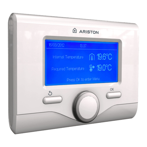
Ariston NIMBUS HYBRID MODULE NET User manual

NIMBUS HYBRID MODULE UNIVERSAL NET
NIMBUS HYBRID MODULE NET
OK
MANUALE D’USO PER L’UTENTE
USER MANUAL
CORREZIONI 28 giugno 2017

2 / IT
Indice:
Garanzia ............................................................................................ 2
Norme di sicurezza........................................................................ 3
Generalità ......................................................................................... 4
Riempimento impianto.................................................................. 4
Utilizzo dell’interfaccia di sistema............................................. 5
Prima accensione........................................................................... 5
Funzionamento modalità manuale/programmato ............... 6
Impostazioni riscaldamento........................................................ 6
Impostazioni rarescamento ...................................................... 6
Impostazione acqua calda sanitaria......................................... 6
Impostazione ibrido....................................................................... 7
Regolazione temperatura ambiente ........................................ 7
Tabella codici errori....................................................................... 8
Funzione antigelo .......................................................................... 8
Manutenzione.................................................................................. 8
Gentile Signora,
Egregio Signore,
la ringraziamo per aver scelto il sistema ARISTON
NIMBUS HYBRID MODULE NET
NIMBUS HYBRID MODULE UNIVERSAL NET
Questo manuale è stato redatto con l’intenzione di infor-
marvi sull’installazione, sull’utilizzo e sulla manutenzione
del sistema NIMBUS HYBRID al fine di permettervi di utiliz-
zarne al meglio tutte le funzioni.
Conservate questo libretto per tutte le possibili informa-
zioni necessarie sul prodotto in seguito alla sua prima ins-
tallazione.
In caso di necessità, il nostro Centro Assistenza Tecnica a
voi più vicino è a vostra disposizione.
Per trovare il Centro Assistenza Tecnica più vicino a voi,
potete consultare il nostro sito internet www.ariston.com.
Vi invitiamo inoltre a far riferimento al Certificato di Garan-
zia che trovate all’interno dell’imballaggio o che il vostro
installatore avrà provveduto a consegnarvi.
Marcatura CE
L’apposizione della marcatura CE sull’apparecchio ne
attesta la conformità alle seguenti Direttive Comunitarie, di
cui soddisfa i requisiti essenziali:
- 2014/35/EU relativa alla sicurezza elettrica
- 2014/30/EU relativa alla compatibilità elettromagnetica
- RoHS2 2011/65/EU relativa alla restrizione all’uso di
determinate sostanze pericolose nelle apparecchiature
elettriche ed elettroniche (EN 50581)
- Regolamento (UE) n. 813/2013 relativo all’ecodesign (n.
2014/C 207/02 - transitional methods of measurement
and calculation)
Garanzia
Ariston vi ore una garanzia di 2 anni a partire dalla messa
in servizio del vostro sistema NIMBUS HYBRID.
Vi preghiamo di leggere le informazioni riportate nel pa-
ragrafo “Condizioni di Garanzia” al fine di conoscere le
modalità di applicazione della garanzia. La messa in ser-
vizio del vostro sistema NIMBUS HYBRID deve essere
eettuata da un Centro Assistenza Tecnica autorizzato, il
quale provvederà a trasmettere al produttore il Certificato
di Garanzia compilato.
Vi preghiamo di assicurarvi dell’avvenuta trasmissione del
Certificato di Garanzia da parte del Centro Assistenza Tec-
nica.
Condizioni di Garanzia
Ariston vi ore una garanzia di 2 anni ( e di 3 anni sul com-
pressore dell’unità esterna) a partire dalla messa in servi-
zio del vostro sistema NIMBUS HYBRID.
Tale garanzia copre tutte le sostituzioni dei pezzi riconos-
ciuti come difettosi, con l’esclusione di danni cagionati ai
componenti da errori durante l’installazione e la messa in
funzione.
Questa garanzia è subordinata all’esecuzione delle opera-
zioni di manutenzione eettuate da un tecnico qualificato,
il quale dovrà controllare, pulire ed eettuare le opportune
regolazioni sul sistema almeno una volta all’anno , come
indicato dalla Circolare Ministeriale del 09/08/78.
La riparazione o sostituzione dei componenti durante il
periodo di validità della garanzia oerta dal costruttore
non determinano un rinnovo della garanzia stessa.
La garanzia oerta dal costruttore non sarà considerata
valida in condizioni di installazione del sistema non ade-
guata, di condizioni di immagazzinamento non idonee
cosi come nei casi in cui il funzionamento difettoso dei
componenti sia dovuto ad un utilizzo improprio del siste-
ma o alla mancata manutenzione dello stesso.
La garanzia si considera valida a condizione che l’installa-
zione e le manutenzioni successive siano state eettuate
a regola d’arte, seguendo le norme in vigore e le istruzioni
presenti sul Manuale di Installazione e che siano inoltre
state realizzate da un tecnico qualificato.
La garanzia oerta dal costruttore non copre i casi in cui:
• I danni ai componenti del sistema siano derivanti da mo-
difiche non previste, eettuate sul sistema, da inadegua-
ta o irregolare pressione dell’acqua, da caratteristiche
dell’acqua che ne inficino la qualità (ad esempio calcare,
sporcizia…) o da applicazione di dierenti tensioni di ali-
mentazione
• L’installazione e le successive operazioni di manuten-
zione vengano eettuate da tecnici non qualificati

IT / 3
Il presente libretto costituisce parte integrante ed es-
senziale del prodotto.
Esso deve essere conservato con cura e deve seguire
il sistema NIMBUS HYBRID in caso di sua cessione ad
altro proprietario o in caso di trasferimento dell’installa-
zione. Leggere attentamente le istruzioni e le avvertenze
contenute nel presente libretto in quanto forniscono im-
portanti indicazioni riguardanti l’uso e la manutenzione.
Questo apparecchio serve a produrre acqua calda per
uso domestico.
Deve essere allacciato ad un impianto di riscaldamento ed
a una rete di distribuzione di acqua calda sanitaria compa-
tibilmente alle sue prestazioni ed alla sua potenza.
E’ vietata l’utilizzazione per scopi diversi da quanto spe-
cificato. Il costruttore non e considerato responsabile per
eventuali danni derivanti da usi impropri, erronei ed irra-
gionevoli o da un mancato rispetto delle istruzioni ripor-
tate sul presente libretto.
L’installazione, la manutenzione e qualsiasi altro intervento
devono essere eettuate da personale in possesso dei
requisiti previsti e nel rispetto delle norme vigenti e delle
indicazioni fornite dal costruttore.
In caso di guasto e/o cattivo funzionamento spegnere
l’apparecchio e non tentare di ripararlo ma rivolgersi a
personale qualificato.
Eventuali riparazioni, eettuate utilizzando esclusivamente
ricambi originali, devono essere eseguite solamente da
tecnici qualificati. Il mancato rispetto di quanto sopra può
compromettere la sicurezza dell’apparecchio e fa deca-
dere ogni responsabilità del costruttore.
Nel caso di lavori o manutenzioni di strutture poste nelle
vicinanze dei condotti o dei dispositivi di scarico dei fumi
e loro accessori, spegnere l’apparecchio. A lavori ultimati
far verificare l’ecienza dei condotti e dei dispositivi da
personale tecnico qualificato.
Prima di eettuare la pulizia delle parti esterne spegnere
l’apparecchio.
Non utilizzare o immagazzinare sostanze facilmente in-
fiammabili nelle vicinanze dell’installazione del vostro sis-
tema NIMBUS HYBRID.
In caso di inutilizzo prolungato del sistema NIMBUS HY-
BRID:
• Disconnettere la presa di alimentazione
• Chiudere il rubinetto di mandata dell’acqua fredda sani-
taria
• Svuotare completamente l’intero circuito, per evitare il
congelamento dell’acqua nelle tubazioni
In caso si decida di dismettere definitivamente il sistema
NIMBUS HYBRID, rivolgersi ad un tecnico qualificato, al
fine di svolgere le operazioni di smantellamento del pro-
dotto.
NORME DI SICUREZZA
Legenda simboli:
Il mancato rispetto dell’avvertenza comporta rischio
di lesioni, in determinate circostanze anche mortali,
per le persone
Il mancato rispetto dell’avvertenza comporta rischio
di danneggiamenti, in determinate circostanze anche
gravi, per oggetti, piante o animali
Non eettuare operazioni che implichino l’apertura
dell’apparecchio.
Folgorazione per contatto con componenti sotto
tensione. Lesioni sotto forma di bruciature dovute
alla presenza di componenti surriscaldati o di
tagli provocati da bordi alati. Danneggiamento
dell’apparecchio.
Non eettuare operazioni che implichino la
rimozione dell’apparecchio dalla sua installazione.
Folgorazione per contatto con conduttori sotto
tensione. Allagamenti per perdita acqua dalle
tubazioni danneggiate.
Non danneggiare i cavi dell’apparecchio.
Folgorazione per contatto con componenti sotto
tensione non protetti.
Non posizionare oggetti sull’apparecchio.
Lesioni provocate dalla caduta di oggetti per eetto
di vibrazioni.
Danneggiamento dell’apparecchio o degli oggetti
posizionati sopra ad esso.
Non salire in piedi sull’apparecchio.
Lesioni provocate dalla caduta dall’apparecchio.
Danneggiamento dell’apparecchio o di oggetti
posizionati. in prossimità dell’apparecchio, a causa
della caduta dallo stesso o della rottura dei suoi
supporti.
Non salire su sedie, sgabelli, scale o supporti
instabili per eettuare la pulizia dell’apparecchio.
Lesioni personali per la caduta dall’alto o per
cesoiamento (scale doppie).
Non eettuare alcuna operazione di pulizia
sull’apparecchio senza prima averlo spento.
Folgorazione per contatto con conduttori sotto
tensione.
Non utilizzare insetticidi, solventi o detersivi
aggressivi per la pulizia dell’apparecchio.
Danneggiamento delle parti in materiale plastico o
verniciate.
Non utilizzare l’apparecchio per scopi diversi da
quello di un normale uso domestico.
Danneggiamento dell’apparecchio per sovraccarico
di funzionamento.
Danneggiamento degli oggetti indebitamente trattati.
Non fare utilizzare l’apparecchio da bambini o
persone inesperte.
Danneggiamento dell’apparecchio per uso improprio.
Nel caso si avverta odore di bruciato o si veda
del fumo fuoriuscire dall’ apparecchio, togliere
l’alimentazione elettrica, aprire le finestre ed
avvisare il tecnico.
Lesioni personali per ustioni, inalazione fumi,
intossicazione.

4 / IT
Generalità
L’interfaccia di sistema SENSYS vi consente una sempli-
ce ed ecace gestione della termoregolazione degli am-
bienti ed il controllo dell’acqua calda sanitaria.
Vi fornisce inoltre il primo aiuto, in caso di malfunziona-
mento del sistema installato, segnalando il tipo di anoma-
lia e suggerendo gli interventi per eliminarla o consiglian-
do l’intervento del Centro Assistenza.
ATTENZIONE!
L’apparecchio può essere utilizzato da bambini di età non inferio-
re a 8 anni e da persone con ridotte capacità fisiche, sensoriali o
mentali, o prive di esperienza o della necessaria conoscenza, pur-
ché sotto sorveglianza oppure dopo che le stesse abbiano ricevuto
istruzioni relative all’uso sicuro dell’apparecchio e alla comprensio-
ne dei pericoli ad esso inerenti. I bambini non devono giocare con
l’apparecchio. La pulizia e la manutenzione destinata ad essere
effettuata dall’utilizzatore non deve essere effettuata da bambini
senza sorveglianza.
Riempimento
(solo per NIMBUS HYBRID MODULE NET)
Il sistema NIMBUS HYBRID funziona a condizione che
l’installazione sia sucientemente riempita d’acqua.
Per le operazioni di riempimento d’acqua, aprire il rubi-
netto (L) e seguire le istruzioni ruportate sul libretto della
caldaia.
L
ATTENZIONE
L’installazione, la prima accensione, le regolazioni devono
essere eettuate, in maniera conforme alle istruzioni for-
nite, esclusivamente da un tecnico qualificato. Il costrutto-
re declina ogni responsabilità in caso di danni subiti dalle
persone, animali o beni, conseguenti ad una installazione
non corretta dell’apparecchio.
Frequenti riempimenti (una volta al mese o più spesso) ne-
cessari al vostro sistema, indicano un possibile problema
sull’installazione (perdite, problemi al vaso di espansione).
Fare riferimento al vostro installatore di fiducia per ana-
lizzare e risolvere il problema rapidamente, prevedendo
danni causati dalla corrosione dei componenti, dovuta ad
un eccessivo ricambio di acqua nel sistema.
PRODOTTO CONFORME ALLA DIRETTIVA
EU 2012/19/EU- D.Lgs.49/2014
ai sensi dell’art. 26 del Decreto
Legislativo 14 marzo 2014, n. 49
“Attuazione della direttiva 2012/19/UE
sui rifiuti di apparecchiature
elettriche ed elettroniche (RAEE)”
Il simbolo del cassonetto barrato riportato sull’apparecchia-
tura o sulla sua confezione indica che il prodotto alla fine della
propria vita utile deve essere raccolto separatamente dagli
altri rifiuti.
L’utente dovrà, pertanto, conferire l’apparecchiatura giunta
a fine vita agli idonei centri comunali di raccolta differenziata
dei rifiuti elettrotecnici ed elettronici.
In alternativa alla gestione autonoma è possibile consegnare
l’apparecchiatura che si desidera smaltire al rivenditore, al
momento dell’acquisto di una nuova apparecchiatura di tipo
equivalente. Presso i rivenditori di prodotti elettronici con
superficie di vendita di almeno 400 m2 è inoltre possibile
consegnare gratuitamente, senza obbligo di acquisto, i pro-
dotti elettronici da smaltire con dimensioni inferiori a 25 cm.
L’adeguata raccolta differenziata per l’avvio successivo
dell’apparecchiatura dismessa al riciclaggio, al trattamento
e allo smaltimento ambientalmente compatibile contribuisce
ad evitare possibili effetti negativi sull’ambiente e sulla salute
e favorisce il reimpiego e/o riciclo dei materiali di cui è com-
posta l’apparecchiatura.
Grazie per aver scelto una Pompa di Calore , compatibile
con Ariston NET*, il servizio ideato e prodotto da Ariston
per fornire una nuova esperienza d’uso del suo sistema di
riscaldamento domestico e dell’acqua sanitaria.
Con Ariston NET può accendere, spegnere e controlla-
re la temperatura del riscaldamento o del rarescamen-
to e dell’acqua sanitaria da smartphone o PC, sempre e
ovunque lei sia. Consente di monitorare costantemente i
consumi energetici garantendo un risparmio sulla bolletta
del gas e l’ avvisa in tempo reale in caso di guasto del-
la caldaia. Inoltre attivando il servizio di teleassistenza, il
centro di assistenza potrà risolvere la maggior parte dei
problemi a distanza. Il centro di assistenza potrà risolvere
la maggior parte dei problemi a distanza, altrimenti fisserà
velocemente un intervento a casa sua.
per maggiori informazioni si colleghi al sito web dedicato
ad Ariston NET www.ariston.com/it/ariston-net.
Oppure ci chiami al’800 300 633. Il nostro Servizio Clienti
è a sua disposizione 7 giorni su 7 (dalle 8 alle 20).
* Verificare la disponibilità del servizio Ariston NET nel vostro paese
con il vostro rivenditore di fiducia.

IT / 5
Interfaccia di sistema :
1. tasto indietro (visualizzazione precedente)
2. manopola
3. tasto OK
(conferma l’operazione o accede al menu principale)
4. Display
Interfaccia di sistema simboli display:
-( ) Estate / Impostazioni acqua calda
- ( ) Inverno
- ( ) Solo riscaldamento /
Impostazioni riscaldamento
- ( ) Rarescamento
- ( ) OFF sistema spento
- ( ) Programmazione oraria
- ( ) Funzionamento manuale
- ( ) Temperatura ambiente desiderata
- ( ) Temperatura ambiente rilevata
- ( ) Temperatura ambiente desiderata deroga
- ( ) Temperatura esterna
- ( ) Funzione AUTO attiva
- ( ) Funzione VACANZA attiva
- ( ) Riscaldamento attivo
- ( ) Sanitario attivo
- ( ) Segnalazione errore
- ( ) Menu completo:
- ( ) Prestazioni sistema
- ( ) Opzioni schermo
- ( ) Impianto a pavimento
- ( ) Circolatore
- ( ) Valvola deviatrice
- ( ST1) Termostato impianto a pavimento
- ( ) Funzione antigelo
- ( ) Modalità sanificazione termica
- ( ) Dispositivo configurabile
- ( ) Pompa di calore
- ( ) Modalità Silenziosa
- ( ) Funzioni speciali
- ( ) Modalità funzionamento Hybrid
- ( ) Deumidificazione
- (AP) Configurazione Acces Point
- ( ) Gateway connesso ad internet
- ( ) Gateway non connesso al router
- ( ) Gateway connesso al router
ma non ad internet
- ( ) Aggiornamento del software in corso
OK
1 2 3 4
Utilizzo dell’interfaccia di sistema.
L’utilizzo dell’interfaccia di sistema è semplice e intuitivo. I
testi presenti nelle varie schermate guidano la navigazio-
ne all’interno dei menu.
Usare il tasto “OK” a destra per entrare nei menu e confer-
mare le impostazioni.
Utilizzare la manopola per selezionare la voce desiderata
e per modificare i valori da impostare.
Utilizzare il tasto “ “per tornare al menu precedente.
PRIMA ACCENSIONE
La prima volta che si collega l’interfaccia di sistema, viene
chiesto di scegliere alcune impostazioni di base.
Come prima cosa è necessario selezionare la lingua
dell’interfaccia utente.
Ruotare la manopola per selezionare la lingua desiderata
e premere il tasto OK per confermare. Procedere con l’im-
postazione della data e ora. Ruotare la manopola per sele-
zionare, premere il tasto OK per confermare la selezione,
ruotare la manopola per impostare il valore.
Premere il tasto OK per confermare.
Salvare le impostazione con il tasto OK.
Premere il tasto OK per accedere al Menu. Utilizzare la
manopola centrale per lo scorrimento della lista menu e la
selezione parametri, premere il tasto OK per confermare.
NOTA
Alcuni parametri sono protetti da un codice di accesso
(codice di sicurezza) che protegge le impostazioni della
caldaia da un utilizzo non autorizzato.

6 / IT
Dalla schermata principale premendo il tasto OK si accede
al seguente menu:
PROGRAMMATO / MANUALE
definisce la modalità di attivazione del riscaldamento/raf-
frescamento:
- ( ) PROGRAMMATO
il riscaldamento/rarescamento funzionerà secondo la
programmazione oraria impostata
- ( ) MANUALE
il riscaldamento/rarescamento funzionerà in modalità
manuale
ESTATE / INVERNO / RAFFRESCAMENTO / OFF
definisce lo stato del sistema;
- ( ) ESTATE
produzione di acqua calda sanitaria, esclusione del ri-
scaldamento.
- ( ) INVERNO
produzione di acqua calda sanitaria e riscaldamento.
- ( ) SOLO RISCALDAMENTO
esclusione riscaldamento bollitore (ove presente).
- ( ) RAFFRESCAMENTO
produzione di acqua calda sanitaria e rarescamento.
- ( ) OFF
sistema spento, funzione antigelo attiva. Quando la fun-
zione antigelo si attiva il display visualizza il simbolo:
“ ”. Questa funzione è una protezione contro il con-
gelamento delle tubature.
MENU COMPLETO
permette di eettuare le impostazioni relative al riscalda-
mento, la produzione di acqua sanitaria, alle regolazioni
specifiche del sistema ibrido e alle impostazioni del di-
splay.
- ( ) IMPOSTAZIONI RISCALDAMENTO
permette di accedere al menu:
- Temperatura impostata riscaldamento.
Permette di impostare le temperature dell’acqua cal-
da del riscaldamento delle zone presenti
- Programmazione oraria
Permette di impostare gli orari di funzionamento del
sistema con temperatura ambiente comfort o ridotta
per tutte le zone in caso di funzionamento in modali-
tà programmato. I testi presenti sul display guidano e
rendono semplice la programmazione.
- Funzione vacanze
La funzione vacanze disattiva il riscaldamento dal
momento dell’attivazione (impostazione ON) fino alla
data di rientro impostata. Nella schermata fonti attive,
quando la funzione vacanze è attiva nella schermata
fonti attive compare l’icona “ ”.
- Funzione )
La funzione AUTO imposta automaticamente il regi-
me di funzionamento del sistema in base al tipo di
installazione e alle condizioni ambientali.
La termoregolazione di un edificio consiste nel man-
tenerne la temperatura interna costante al variare
della temperatura esterna. Il vostro sistema NIMBUS
HYBRID è dotato di una serie di Funzioni AUTO (Re-
golazione Automatica).
Grazie a questa tecnologia, il sistema garantisce la
temperatura desiderata, regolando i parametri al fine
di contenere il consumo di energia elettrica.
Contattare il vostro installatore di fiducia o il Centro
Assistenza Tecnica più vicino cosi da ottenere tutte le
informazioni necessarie sulla configurazione e il fun-
zionamento del sistema.
- Estate/inverno automatica
(permette l’attivazione della richiesta di calore in ri-
scaldamento quando la temperatura esterna scende
sotto la temperatura impostata dal parametro “Limite
temp. estate/inverno auto” per un tempo impostato
sul parametro “ritardo di commutazione estate/inver-
no”, o l’interruzione della richiesta di calore quando la
temperatura esterna sale sopra la temperatura impo-
stata.
- Zona1
- Attivazione funzione estate/inverno auto Z1
(attiva la funzione per la zona1)
- Limite temp. estate/inverno auto Z1
(soglia di commutazione della temperatura esterna
per l’attivazione/disattivazione della richiesta di ca-
lore in riscaldamento )
- Ritardo commutazione estate/inverno Z1
(ritardo di commutazione per l’attivazione/disattiva-
zione della richiesta calore quando la temperatura
esterna raggiunge la temperatura impostata).
- ( ) IMPOSTAZIONI RAFFRESCAMENTO
permette di accedere al menu:
- Temperatura impostata rarescamento
permette di impostare la temperatura di mandata
dell’acqua del circuito di rarescamento per tutte le
zone presenti
- Programmazione oraria rarescamento
Permette di impostare gli orari di funzionamento del
sistema di rarescametno con temperatura ambiente
comfort o ridotta per tutte le zone in caso di funziona-
mento in modalità programmato
- Funzione )
La funzione AUTO imposta automaticamente il regi-
me di funzionamento del sistema in base al tipo di
installazione e alle condizioni ambientali.
Contattare il vostro installatore di fiducia o il Centro
Assistenza Tecnica più vicino cosi da ottenere tutte
le informazioni necessarie sulla confi gurazione e il
funzionamento del sistema.
- ( ) IMPOSTAZIONI ACQUA CALDA SANITARIA
permette di accedere al menu:
- Temperatura comfort acqua calda
Iimpostazione temperatura comfort
- Programmazione oraria acqua calda sanitaria
(solo per sistemi con caldaia system e bollitore da
accumulo) permette di impostare gli orari di riscalda-
mento del bollitore con temperature comfort o ridotta.
- Funzione comfort
ATTENZIONE! in caso di installazioni con caldaia mi-
sta (senza accumulo sanitario) selezionare “Disabili-
tata”. In caso di installazione con caldaia system ed
accumulo definisce la modalità di attivazione della
temperatura comfort (disabilitata, temporizzata o
sempre attiva). Durante la carica dell’accumulo sanita-
rio il display caldia visualizza il simbolo riscaldamento
attivo “ ”

IT / 7
- Tank charge mode
(solo per sistemi con caldaia system e bollitore da ac-
cumulo) definisce la modalità di messa a temperatura
del bollitore:
STANDARD : il sistema ibrido attiva PdC e caldaia
automaticamente secondo criteri di economicità e
comfort..
SOLO PDC : la caldaia viene esclusa
FAST: la caldaia viene attivata contemporaneamente
alla pompa di calore per scaldare il bollitore nel tem-
po più breve possibile.
- ( )IMPOSTAZIONI IBRIDO
permette di accedere al menu:
- Logica energy manager
definisce la logica di funzionamento del sistema ibrido:
MASSIMO RISPARMIO:
caldaia e pompa di calore vengono attivati in maniera
da garantire il costo minimo dell’energia in base alle
tarie inserite all’atto dell’installazione del sistema
MASSIMA ECOLOGIA:
caldaia e pompa di calore vengono attivati in maniera
da garantire il minimo consumo di energia primaria
- Modalità ibrido
Permette di selezionare la sorgente di calore (caldaia
o pompa di calore) da utilizzare.
AUTO: il sistema sceglierà automaticamente il dispo-
sitivo più conveniente/ecologico da attivare.
SOLO CALDAIA : la pompa di calore viene esclusa
SOLO PDC : la caldaia verrà esclusa
- FUNZIONI SPECIALI
definisce la logica di funzionamento del sistema ibrido:
- Modo silenzioso:
questa funzione limita la potenza del sistema pompa
di calore per ridurne la rumorosità in un periodo di
tempo nell’arco della giornata. Nel menu occorre de-
finire l’attivazione (ON/OFF) indicare l’orario di inizio e
di disattivazione.
- Delta T Setpoint Sanitario fotovoltaico
La funzione permette di incrementare la temperatura
di setpoint sanitario quando è disponibile energia ex-
tra dal sistema fotovoltaico. Premere il tasto OK per
confermare. Premere il tasto indietro “ “per ritorna-
re alla visualizzazione precedente.
- PRESTAZIONI DEL SISTEMA
accede alla visualizzazione delle prestazioni del siste-
ma ibrido
Il sistema di misurazione dei consumi energetici integra-
to in questo prodotto si basa su una stima. Ci possono
quindi essere dierenze tra il consumo eettivo (o misu-
rato da un altro sistema) e quello visualizzato.
- IMPOSTAZIONI SCHERMO
permette di personalizzare la schermata del display se-
condo questo menu:
- Lingua
- Data e ora
- Schermata iniziale
- Luminosità in standby
- Retroilluminazione
- Temporizzazione schermata iniziale
REGOLAZIONE TEMPERATURA AMBIENTE
E’ possibile regolare la temperatura ambiente In base alla
modalità di funzionamento scelta, programmato o manua-
le.
- Regolazione temperatura ambiente in modalità ma-
nuale
Ruotare la manopola per impostare il valore di temperatu-
ra ambiente che si desidera. Il display visualizza il valore
impostato.
Premere il tasto OK per confermare.
Il display ritorna alla visualizzazione predente.
- Regolazione temperatura ambiente in modalità
programmazione oraria
Durante il funzionamento della programmazione oraria
è possibile modificare temporaneamente la temperatura
ambiente impostata.
Ruotare la manopola ed impostare il valore di temperatura
ambiente che si desidera. Premere il tasto OK.
Il display visualizza la temperatura impostata e l’ora fino in
cui si desidera mantenere la modifica.
Ruotare la manopola per impostare l’ora di fine modifica,
premere il tasto OK per confermare.
Il display visualizza il simbolo “ ” in corrispondenza del
valore di temperatura desiderata per il periodo di modifica.
Premere il tasto indietro “ “ per uscire dalla regolazione
senza salvare la modifica.
L’interfaccia di sistema manterrà il valore di temperatura
fino al termine del tempo impostato, finito il quale tornerà
alla temperatura ambiente pre-impostata.
- Regolazione temperatura ambiente con
funzione AUTO attiva.
Nel caso in cui la temperatura dell’acqua di riscaldamento
o rarescamento non corrisponda a quella desiderata è
possibile aumentarla o diminuirla tramite parametro “Tem-
peratura impostata riscaldamento” o “Temperatura impo-
stata rarescamento”.
Il display visualizza la barra di correzione. Premere il ta-
sto OK per confermare la correzione o premere il tasto
indietro “ “ per ritornare alle visualizzazione precedente
senza salvare.
Ruotare la manopola e selezionare:
-
ARISTON NET
Per informazioni collegarsi al sito web dedicato ad Ariston NET*
www.ariston.com/it/ariston-net
o chiamare il numero 800 300 633 il Servizio Clienti è
attivo 7 giorni su 7 (dalle 8 alle 20).

8 / IT
FUNZIONE ANTIGELO
Il sistema NIMBUS HYBRID è dotato di una funziona antigelo, la quale eettua un controllo sulla temperatura dell’acqua in uscita
dall’unità interna, attivando i dispositivi presenti nel sistema, in caso essa rimanga al di sotto degli 8 °C per più di 30 secondi.
ATTENZIONE
La funzione antigelo funziona correttamente se:
• La pressione dell’impianto è compresa tra 0.6 e 3 bar
• Il sistema è alimentato elettricamente
• Al momento della richiesta di attivazione della funzione antigelo, non è presente alcun errore di funzionamento
MANUTENZIONE
La manutenzione dei sistema NIMBUS HYBRID è obbligatoria ed indispensabile.
Al fine di assicurare il corretto funzionamento, la sicurezza dell’apparato e la durata di vita del sistema stesso.
TABELLA CODICI ERRORI IBRIDO
In caso di blocco sul display dell’interfaccia di sistema viene visualizzato un codice errore che si riferisce al tipo di arresto
ed alla causa che lo ha generato.
Per ripristinare il normale funzionamento seguire le istruzioni riportate sul display o se l’errore persiste si consiglia l’inter-
vento del Centro di Assistenza Tecnico autorizzato.
ERRORE DESCRIZIONE RISOLUZIONE
1 14 Sonda Esterna Difettosa - Attivazione della termoregolazione basata sulla sonda esterna.
- Sonda esterna non connessa o danneggiata.
4 20* Sovraccarico alimentazione bus
9 02 sonda mandata primario difettosa Sonda di mandata non connessa o difettosa
9 10 Errore comunicazione con HP - Controllare il cavo di connessione modbus.
- Led rosso fisso-> sostituire scheda TDM
9 24 Errore Comunicazione BUS tra EM e TDM - Controllare cablaggio tra scheda TDM ed Energy Manager
9 33 sovratemperatura circuito primario - Controllare il flusso nel circuito primario
9 34 sonda bollitore difettosa - Sonda bollitore non collegata o difettosa
9 35 sovratemperatura bollitore - Controllare valvola 3 vie bloccata nella posizione sanitario
9 36 Errore termostato pavimento - Controllare il flusso nell’impianto a pavimento
9 37 Errore circolazione acqua - Controllare attivazione del circolatore principale
- Controllare il flussimetro tramite il parametro 12.13.3
9 38 Errore Anodo
- Controllare la connessione dell’Anodo
- Controllare presenza acqua nel bollitore
- Controllare stato dell’Anodo
9 40 Definire schema idraulico Schema idraulico non selezionato tramite il parametro 12.2.0
9 41 HV IN1 non definito Funzione non selezionata tramite il parametro 12.1.0
9 42 HV IN2 non definito Funzione non selezionata tramite il parametro 12.1.1
9 44 Sovratemperatura in rarescamento Controllare il flusso nel circuito rarescamento
9 45 Flussostato incollato
- Controllare se il circolatore principale è attivo prima della richiesta
calore
- Controllare il flusso con il valore flussimetro tramite il parametro
12.13.3
9 46 Errore compressore HP Controllare la frequenza del compressore dopo la fine della richiesta
calore tramite il parametro 12.14.1
9 55 Flussostato acqua Controllare il posizionamento delle sonde di mandata e ritorno.
9 58 Sovratemperatura buer Carica del Buer inibita
9 59 Errore sonda buer alta Carica del Buer inibita
9 70 Configurazione pompa aux non corretta Errore visualizzato per 30 secondi e memorizzato nello storico
2 P2 Ciclo di sanificazione non completato
Temperatura sanificazione termica non raggiunta in 6h:
- Controllare prelievo di acqua calda sanitaria durante il ciclo di
sanificazione termica
- Controllare il flusso di acqua calda sanitaria durante il ciclo di
sanificazione termica
- Controllare l’accensione della resistenza elettrica
2 P7 Errore pre-circolazione Flusso non rilevato per 5 minuti durante la pre-circolazione
2 P9
Configurazione d’ingresso SG ready non completato
Solo uno dei parametri 12.1.0 o 12.1.1 è impostato come input SG
Ready

IT / 9
LISTA ERRORI UNITÀ ESTERNA
ERRORE TDM
DESCRIZIONE
RESET
HP POWER OFF
SERVICE RESET
905
Errore pilotaggio compressore
x
906 Errore pilotaggio ventilatore x
907 Errore pilotaggio valvola 4 vie x
908 Errore pilotaggio valvola espansione x
909
Ventilatore fermo a macchina accesa
x
947 Errore valvola 4 vie x
912 Errore valvola 4 vie x
948 Errore sonda TD -- --
949
Errore sonda TS
--
--
911
Errore sonda TE
--
--
952 Errore sensore TO -- --
913 Errore sonda LWT -- --
914 Errore sonda TR -- --
916
Errore sonda TEO
--
--
915 Errore comunicazione TDM -- --
953 Errore pilotaggio riscaldatore del compres-
sore -- --
954 Errore pilotaggio resistenza nel bacino -- --
956 Errore configurazione modello compressore -- --
957 Errore configurazione modello ventilatore -- --
922 Errore SST troppo bassa x
917 Errore congelamento, temperature LWT e/o
TR troppa bassa. -- x
951
Errore sovratemperatura TD.
x
950
Errore sovratemperatura TD.
--
x
919 Errore SDT troppo alta x
960 Errore sonda EWT -- --
931 Errore inverter * -- --
962
Defrost Energy
x
* Il parametro 12.13.1 mostra l’errore inverter riportato nella tabel-
la a fianco «Lista errori inverter».
ERRORE
INVERTER DESCRIZIONE 1ph 3ph
1 Sovratemperatura Dissipatore x x
2 Sovracorrente IPM Compressore x
3
Start-up Compressore Fallito
x
4 Sovracorrente Compressore x x
5 Mancanza di fase AC Ingresso x
6 Errore Misura Corrente IPM Compressore x
7Tensione DC bus troppo bassa
all’avviamento x
8
Sovratensione DC bus
x
9 Sottotensione DC bus x
10 Sottotensione AC input x
11 Sovracorrente AC input x
12
Errore Misura Tensione AC input
x
13 Errore di comunicazione interna tra
microcontrollori della scheda
x
14 Errore sensore Temperatura Dissipatore x
15 Errore di comunicazione interna tra
microcontrollori della scheda x
16 Interruzione della comunicazione tra
inverter e TDM x
17
Sovratemperatura IPM
x
18 Errore modello Compressore
(non configurato) x x
19 Protezione Alta Pressione x x
21 Start-up Fan 1 fallito x
27
Errore pilotaggio Fan 1
x
29
Start-up Fan 2 fallito
x
35 Ingresso High Pressure aperto (ci sarà
sempre un ponticello) x x
36 Ingresso Low Pressure aperto (ci sarà
sempre un ponticello) x x
37 Ingresso Termostato Compressore
(ci sarà sempre un ponticello) x x
38
Errore di comunicazione tra le schede
x
39 Sovracorrente IPM x
40 Start-up Compressore Fallito x
41 Sovracorrente Compressore x
42
Errore Misura Corrente IPM
x
43
Sovratemperatura Dissipatore
x
44 Tensione DC bus troppo bassa all’avvia-
mento x
45 Sovratensione DC bus x
46 Sottotensione DC bus x
47
Sottotensione AC input
x
48 Sovratensione AC input x
49 fermata di emergenza del compressore x
50 Errore Misura Tensione AC input x
51 Errore sensore Temperatura Dissipatore x
52 Errore di comunicazione interna tra micro-
controllori della scheda
x
53 Errore di comunicazione con la scheda di
controllo IDU x
LISTA ERRORI INVERTER
(*) Sovraccarico alimentazione BUS
E’ possibile il verificarsi di un errore di sovraccarico alimentazione BUS, dovuto alla connessione di tre o più
dispositivi presenti nel sistema installato. I dispositivi che possono sovralimentare la rete BUS sono:
- Modulo Multizona
- Gruppo pompa solare
- Modulo per la produzione istantanea di acqua calda sanitaria
Per evitare il rischio di sovraccarico alimentazione BUS, è necessario portare il microswitch 1 di una delle sche-
de elettroniche presente negli apparecchi connessi al sistema (tranne la caldaia) nella posizione OFF, come
mostrato in figura.
1
ON
OFF
2
microswitch

10 / GB
Table of contents:
Guarantee........................................................................................10
Safety regulations ..........................................................................11
Overview..........................................................................................12
System filling...................................................................................12
Using the system interface. .......................................................13
Initial start up...................................................................................13
Manual and programmed heating modes operation ........14
Heating settings.............................................................................14
Cooling settings.............................................................................14
Domestic hot water settings......................................................14
Hybrid settings...............................................................................15
Room temperature adjustment.................................................15
Table of error codes.....................................................................16
Anti-freeze function......................................................................16
Maintenance ...................................................................................16
Dear
Customer,
Thank you for choosing the ARISTON
NIMBUS HYBRID MODULE NET
NIMBUS HYBRID MODULE UNIVERSAL NET system.
This manual has been written with the intention of informing
you about NIMBUS HYBRID system installation, usage and
maintenance, in order to allow best usage of all functions.
Keep this booklet, as it contains all the information you
will possibly need regarding the product, following its first
installation.
If needed, your nearest Technical Service Centre is at your
disposal.
To find the Technical Service Centre nearest you, please
visit our website www.ariston.com.
Please also refer to the Guarantee Certificate that you will
find inside the packaging, or which your installer will have
given to you.
CE mark
- 2014/30/EU - relating to Electromagnetic Compatibility
- 2014/35/EU - related to electrical safety (LVD)
- RoHS2 2011/65/EU related to the restriction of the use
of certain dangerous substances in electrical and elec-
tronic equipment (EN 50581)
- Regulation (EU) No. 813/2013 on ecodesign (no. 2014/C
207/02 - transitional methods of measurement and cal-
culation)
Guarantee
Ariston oers a 2 year guarantee from commissioning of
your NIMBUS HYBRID system.
Please read the information contained in the “Guarantee
terms” section to find out how the guarantee applies.
Commissioning of your NIMBUS HYBRID system must be
carried out by an authorized Technical Service Centre,
who will send the completed Guarantee Certificate to the
manufacturer.
Please check that the Technical Service Centre has
forwarded your Guarantee Certificate.
GUARANTEE TERMS
Ariston oers a 2 year guarantee from commissioning (and
3 years for the external unit compressor) of your NIMBUS
HYBRID system. This guarantee covers all replacements
of components recognized as defective, excluding any
damage caused to components from installation and
commissioning errors.
This guarantee is subject to maintenance operations
being carried out by a qualified technician, who must to
check, clean, and carry out any necessary adjustments to,
the system at least once a year, as indicated in Ministerial
Circular of 09/08/78.
The repair or replacement of components during the validity
period of the guarantee oered by the manufacturer, do
not result in renewal of that guarantee.
The guarantee oered by the manufacturer will be
considered invalid in the event of inadequate system
installation or unsuitable storage conditions, as well as in
cases where component malfunction of is due to improper
use or lack of maintenance of the system.
The guarantee is considered valid on condition that
installation and subsequent maintenance be professionally
carried out, in accordance with applicable standards and
the Installation Manual instructions, and which also are
carried out by a qualified technician.
The guarantee oered by the manufacturer does not
cover cases in which:
• Damagetosystemcomponentsiscausedbyunauthorised
changes made to the system, by inadequate or uneven
water pressure, by the presence of characteristics which
aect water quality (such as limestone, dirt, etc.), or by
the application of dierent supply voltages
• The installation and subsequent maintenance operations
are carried out by unqualified technicians

GB / 11
This manual constitutes an integral and essential part of
the product.
It must be stored carefully and remain with the product
at all times, in the event of transfer to a new owner or
user, or transfer of the installation. Carefully read the
instructions and warnings contained in this booklet: they
provide important information concerning operation
and maintenance.
This appliance is designed to produce hot water for
domestic use.
It must be connected to a heating system and a distribution
network for domestic hot water, both of which must be
compatible with the appliance’s performance and power
levels.
It is strictly forbidden to use the appliance for purposes
other than those specified. The manufacturer shall not
be held liable for any damage due to improper, incorrect
or unreasonable use or due to failure to comply with the
indications outlined in this manual.
Installation, maintenance and any other interventions must
be performed by fully qualified personnel, in conformity
with all applicable regulations and the instructions
provided by the manufacturer.
In the event of faults and/or malfunction, switch the device
o and do not attempt to perform any repairs yourself.
Contact a qualified professional instead.
Any repairs must be carried out by qualified technicians
using original spare parts only. Failure to comply with the
above may jeopardise the device’s safety and void the
manufacturer’s liability.
In the event of any maintenance or other work on structures
in the immediate vicinity of the ducts or flue gas discharge
devices and relevant accessories, switch o the appliance.
Once work is completed, ask a qualified technician to
check the eciency of the ducts and devices.
Before cleaning the outer parts, switch o the appliance.
Do not use or store flammable substances near the
installation location of your NIMBUS HYBRID MODULE
NET system.
Should the NIMBUS HYBRID MODULE NET system not be
used for a prolonged period of time:
• Disconnect the power socket
• Close the domestic cold water delivery tap
• Completely empty the entire circuit to prevent water
freezing in the piping
If you decide to permanently dispose of your NIMBUS
HYBRID MODULE NET system, contact a qualified
technician, in order to carry out the product dismantling
operations.
SAFETY RULES
Symbol legend:
Failure to comply with this warning implies the risk of
injury to persons, which in some circumstances may
be fatal
Failure to comply with this warning implies the
risk of damage – even serious damage in some
circumstances – to property and plants or harm to
animals
Do not perform operations that involve opening
the appliance.
Electrocution from contact with live components.
Injuries in the form of burns due to overheated
components or cuts caused by sharp edges.
Damage to the device.
Do not perform operations that involve removing
the appliance from its installation location.
Electrocution caused by contact with live wires.
Flooding due to water leaking from damaged
piping.
Do not damage the appliance cables.
Electrocution from contact with unprotected live
components.
Do not place objects on top of the appliance.
Risk of injuries from an object falling o the
appliance as a result of vibration.
Damage to the appliance or to the objects placed
upon it.
Do not climb on the appliance.
Injuries caused by falling o the appliance.
Damage to the appliance or to objects placed
near the appliance, caused by the appliance
falling or its supports breaking.
Do not climb onto unstable chairs, stools,
ladders or other props to clean the appliance.
Personal injuries due to falling from a height or to
crushing (stepladders shutting accidentally).
Never clean the appliance without having
switched it o first.
Electrocution caused by contact with live wires.
Do not use any insecticides, solvents or
aggressive detergents to clean the appliance.
Damage to plastic or painted parts.
Do not use the appliance for any purpose other
than normal domestic use.
Damage to the appliance caused by operational
overload.
Damage to objects caused by improper use.
Do not allow children or inexperienced people
to operate the appliance.
Damage to the appliance due to improper use.
If you notice a burnt smell or see smoke coming
out of the appliance, disconnect it from the
power supply, open all windows and contact the
technician.
Personal injuries caused by burns, smoke
inhalation, intoxication.

12 / GB
Overview
The SENSYS system interface oers simple and ecient
room temperature adjustment and domestic hot water
control.
It also provides initial help in the event of an installed system
malfunction, indicating the type of anomaly detected,
suggesting action to solve the problem or recommending
you call the Service Centre for assistance.
WARNING!
This appliance can be used by children aged from 8 years
and above and person with reduced physical, sensory or
mental capabilities or lack of experience and knowledge if
they have been given supervision or instruction concerning
use of the appliance in a safe way and understand the
hazards involved.
Children shall not play with the appliance. Cleaning and
user maintenance shall not be made by children without
supervision.
THIS PRODUCT CONFORMS
TO EU DIRECTIVE
2002/96/EC
The barred dustbin symbol appearing on the appliance
indicates that the product must be disposed of
separately from household waste once it reaches the
end of its lifespan, and transferred to a waste disposal
site for electric and electronic equipment, or returned
to the dealer when purchasing a new appliance of the
same kind.
Theuserisresponsiblefordeliveringthedecommissioned
appliance to a suitable waste disposal site.
Proper separated collection of the decommissioned
appliance and its subsequent eco-compatible recycling,
treatment and disposal helps to prevent negative
eects on the environment and human health, besides
encouraging reuse of the materials comprising the
product.
For further details on the available waste collection
systems, contact your local waste disposal oce, or the
dealer from which the product was purchased.
System filling
(only for NIMBUS HYBRID MODULE NET)
NIMBUS HYBRID can work only if the system is filled.
The system filling operation can by carried out rotating the
filling valve (L), following the indication on the boiler boo-
klet.
L
WARNING
The installation, initial start up, and configuration must
be carried out in accordance with the instructions, by a
qualified technician only. The manufacturer declines all
responsibility for damages caused to people, animals
or possessions following incorrect installation of the
appliance.
If frequent fillings (once a month or more frequently)
are required for your system, this indicates a potential
problem with the installation (leaks, expansion vessel
problems). Contact your trusted installer to analyse and
solve the problem quickly, to prevent damage caused by
corrosion of components, due to excessive system water
replacement.
Thank you for choosing Hybrid Module, is compatible with
Ariston NET*, the service designed and manufactured by
Ariston, to provide a whole new experience in using a do-
mestic heating/cooling and water system.
Ariston Net allows you to start, stop and check the tem-
perature of domestic heating/cooling and water anytime,
anywhere from a smartphone or PC.
It allows you to constantly monitor energy consumption to
ensure you save on your gas bill. It also notifies you in real
time if there is a boiler failure.
If a teleassistance service is activated, the service centre
will be able to solve problems remotely where possible or
arrange an appointment at your earliest convenience.
*availability of the service must be verified with your local Gas Safe regi-
stered engineer. For more information call us on 0333 240 8777.

GB / 13
Buttons and display:
1. back button (previous display)
2. knob
3. OK button (to confirm operation or access main menu)
4. DISPLAY
System interface display symbols:
-( ) Summer / DHW settings
- ( ) Winter
- ( ) Only Winter / CH settings (where present)
- ( ) Cooling (where present)
- ( ) OFF system o
- ( ) Schedule programming
- ( ) Manual operation
- ( ) Desired room temperature
- ( ) Room temperature detected
- ( ) Desired room temperature override
- ( ) Outdoor temperature
- ( ) AUTO function enabled
- ( ) HOLIDAY function enabled
- ( ) Central heating active
- ( ) Domestic hot water enabled
- ( ) Error indication
- ( ) Complete menu:
- ( ) System performance
- ( ) Display options
- ( ) Under-floor heating system
- ( ) Circulation pump
- ( ) Diverter valve
- ( ST1) Under-floor heating system thermostat
- (
)
Anti-frost function
- ( ) Thermal sanitation function
- ( ) Configurable device
- ( ) Heat pump
- ( ) Silent operation mode
- ( ) Special functions
- ( ) Dehumidification
(AP) Access Point configuration
- ( ) Gateway connected to internet
- ( ) Gateway not connected to router
- ( ) Gateway connected to router but not
to the internet
- ( ) Software update in progress
OK
1 2 3 4
Using the system interface.
The system interface is simple and intuitive to use. Texts
shown on the various screens guide you through the
menu navigation.
Use the “OK” button on the right to access menu items
and confirm settings.
Use the knob to select the required menu item, and to
change settings values.
Use the “ ” button to return to the previous menu.
INITIAL START UP
The first time the system interface is connected, you will
be asked to select a few basic settings.
First, you will need to select the user interface language.
Turn the knob and select the desired language, then press
the OK button to confirm. Move on to setting the date and
time. Turn the knob to make a selection, press the OK
button to confirm your selection, turn the knob to set the
value.
Press the OK button to confirm.
Save the settings by pressing OK.
Press the OK button to access the Menu. Use the knob
in the centre to scroll through the menu list and select a
parameter, then press OK to confirm.
NOTE
Some parameters are protected with an access code
(safety code) which protects the boiler settings from
unauthorised use.

14 / GB
Press the OK button on the main screen to access the
following menu:
PROGRAMMED/MANUAL
defines the heating activation mode:
- ( ) PROGRAMMED
the heating will operate in accordance with the set
schedule programming
- ( ) MANUAL
the heating will operate in manual mode
SUMMER/WINTER/OFF
defines the system status:
- ( ) SUMMER
domestic hot water produced, heating o.
- ( ) WINTER
domestic hot water produced, heating on.
- ( ) HEATING ONLY
indirect cylinder heating (where present) o.
- ( ) COOLING
domestic hot water produced, cooling on (where
present).
- ( ) OFF
system o, anti-freeze function enabled. When the anti-
freeze unction is enabled, the display screen shows the
symbol:
“ ”. This function is a protection against freezing of
the piping.
COMPLETE MENU
allows you to adjust the heating, domestic hot water
production, specific hybrid system control, and display
settings.
- ( ) HEATING SETTINGS
allows access to menu:
- Heating set point
It allows the heating system teperature setting for all
the heating zones available.
- Schedule programming
allows you to set the system operating hours at
comfort or reduced room temperature for all zones
when operating in programmed mode. The texts
shown on the display guide you and make the
programming simple.
- Holiday function
The holiday function disables the heating from the
moment it is activated (setting ON) until the return
date set.
The “ ” icon appears on the active sources screen
when the holiday function is enabled.
- function
The AUTO function automatically sets the system
operating regime in accordance with the installation
type and the environmental conditions.
The temperature adjustment of a building consists of
maintaining the indoor temperature at a constant level
while the temperature outside changes. Your NIMBUS
HYBRID MODULE NET system is equipped with a
series of AUTO functions (automatic adjustment).
Using this technology, the system maintains the
desired temperature, by adjusting the parameters in
order to limit electrical energy consumption.
Contact your trusted installer or the nearest Technical
Service Centre to obtain all the necessary information
on the configuration and operation of the system.
- Summer/Winter Changeover
(allows the activation of the heating demand,
when the outdoor temperature drops below the
temperature set by the parameter “S/W temperature
threshold” setting a time delay on the switching with
the parameter “S/W delay time” or the interruption of
the heat demand when the outside temperature rises
above the set temperature).
- Zone1
-S/W function activation
(ctivation the function for zone 1)
- S/W temperature threshold
(External temperature switching threshold for the
activation / deactivation of the heat demand)
- S/W delay time
(Switching delay for the activation / deactivation of
the heat demand when the outside temperature get
to the set temperature).
-( ) COOLING SETTINGS
allows access to menu:
- Cooling set point
It allows the cooling system teperature setting for all
the cooling zones available.
- Schedule programming
allows you to set the system operating hours at
comfort or reduced room temperature for all zones
when operating in programmed mode. The texts
shown on the display guide you and make the
programming simple.
- function
The AUTO function automatically sets the system
operating regime in accordance with the installation
type and the environmental conditions.
Contact your trusted installer or the nearest Technical
Service Centre to obtain all the necessary information
on the configuration and operation of the system.
- ( ) DOMESTIC HOT WATER SETTINGS
allows access to menu:
- DHW comfort temperature
Comfort temperature settings
- Domestic hot water schedule programming
(only for systems with boiler system and storage
cylinder) allows you to set indirect cylinder heating
times at comfort or reduced temperature.
- Comfort function
WARNING! For combination boiler installations
(without hot water storage tank), select “Disabled”.
For boiler system and storage installation this defines
how the comfort temperature is activated (disabled,
timed or always enabled). When the hot water storage
tank is charging the boiler display shows the active
heating symbol “ ”.

GB / 15
ROOM TEMPERATURE ADJUSTMENT
You can adjust room temperature based on the operating
mode chosen, programmed or manual.
- Manual mode room temperature adjustment
Turn the knob to set the desired room temperature value.
The set value appears on the display.
Press the OK button to confirm.
The display reverts to showing the previous screen.
- Schedule programming mode room temperature
adjustment
During operation in scheduled programming mode, the
set room temperature can be changed temporarily.
Turn the knob to set the desired room temperature value.
Press the OK button.
The display shows the set temperature and the time at
which you want the change to end.
Turn the knob to set the change end time and press the
OK button to confirm.
The display shows the symbol “ ” alongside the
desired temperature value set for the change period.
Press the back button “ ” to exit adjustment without
saving the changes.
The system interface will maintain the temperature value
until the end of the set time period, when the pre-set room
temperature is restored.
- Room temperature adjustment with
AUTO function active
If the temperature of the heating hot water does not
correspond to the desired level, it can be increased or
diminished through the “CH Setpoint temp” parameter.
The display visualises the correction bar.
Press OK to confi rm the correction, or press the back
button “ ” to return to the previous visualisation without
saving the settings.
- Tank charge mode
(only for systems with boiler system and storage
cylinder) defines the indirect cylinder heating mode:
STANDARD: the hybrid system automatically activates
heat pump and boiler according to economy and
comfort criteria.
HEAT PUMP ONLY: the boiler is switched o.
FAST: the boiler is activated at the same time as the
heat pump, to heat the indirect cylinder in the shortest
possible time.
- ( )HYBRID SETTINGS
allows access to menu:
- Energy manager logic
defines operation logic for the hybrid system:
MAXIMUM SAVING:
boiler and heat pump are activated so as to ensure
the lowest energy cost based on the rates set when
you install the system.
MAXIMUM ENVIRONMENTAL PERFORMANCE:
boiler and heat pump are enabled so as to ensure
minimum consumption of primary energy.
- Hybrid mode
allows you to select the heat source (boiler or heat
pump) to be used.
AUTO: the system automatically chooses the most
convenient/ecological device to enable.
BOILER ONLY: the heat pump is switched o.
HEAT PUMP ONLY: the boiler is switched o.
- SPECIAL FUNCTIONS
defines operation logic for the hybrid system:
- Silent operation mode:
this function limits the system heat pump power to
reduce noise within a daytime time period. In the
menu you need to define its activation (ON/OFF) and
indicate the start and deactivation times.
- Photovoltaic hot water setpoint delta T
This function increases the hot water setpoint when
extra power is available from the photovoltaic system.
Press the OK button to confirm. Press the back button
“ ” to return to the previous screen.
- SYSTEM PERFORMANCE
accesses the hybrid system performance display:
The energy consumption measurement system
integrated in this product is based on an estimate.
There may therefore be dierences between the actual
consumption (or that measured by another system) and
the one displayed.
- SCREEN SETTINGS
allows you to customise the screen display using the
following menu items:
- Language
- Date and time
- Start screen
- Standby brightness
- Backlight
- Start screen time
-
ARISTON NET
availability of the service must be verified with your local
Gas Safe registered engineer.
For more information call us on
0333 240 8777.

16 / GB
ANTI-FREEZE FUNCTION
The NIMBUS HYBRID system is equipped with an anti-freeze function, which controls the temperature of the water
discharged from the internal unit by enabling the system devices in the event that the temperature remains below 8 °C
for more than two consecutive minutes.
WARNING
The anti-freeze function is working correctly if:
• The static pressure of the system is between 0.6 and 3 bars
• The system is powered electrically
• When the anti-freeze function activation request is made, there are no operational errors present
MAINTENANCE
Maintenance of the NIMBUS HYBRID system is mandatory and indispensable to ensuring correct operation, apparatus
safety, and the service life of the system itself.
TABLE HYBRID ERROR CODES
If the system shuts down, a code will appear on the system interface display signalling the type of shutdown and the
reason behind it.
To restore normal operation, follow the instructions provided on the display or, if the error persists, contact an authorised
Technical Service Centre for assistance.
ERROR DESCRIPTION TROUBLESHOOTING
1 14 Faulty outdoor sensor Activation of thermoregulation based on outdoor sensor and outdoor
sensor not connected or damaged
4 20* Bus power supply overload
9 02 Faulty primary delivery sensor Flow sensor not connected or damaged
9 10 HP communication error - Check the wiring connection of the modbus cable.
- Red led on TDM not blinking-> change TDM control board
9 24 Ebus Communication error between EM and
TDM - Check wiring connection between TDM end Energy Manager
9 33 Overheat - Check water fl ow of the heating circuit
9 34 DHW Tank sensor damaged - DHW tank sensor not connected or damaged
9 35 Tank overtemperature - Check 3-way valve (DIV1) blocked in DHW position
9 36 Floor Thermostat 1 error - Check water circulation of the underfloor zone
9 37 No circulation error - Check main circulation activation
- Check water flow sensor detection by par. 12.13.3
9 38 Anode Fault
- Check anode connection
- Check water presence in the tank
- Check anode statu
9 40 Hydraulic scheme not defined Hydraulic scheme not selected by parameter 12.2.0
9 41 HIV IN1 not defined Function not selected by parameter 12.1.0
9 42 HIV IN2 not defined Function not selected by parameter 12.1.1
9 44 Cooling overtemperature Check water flow of the cooling circuit
9 45 Flow switch stuck
- Check if main circulation is active before the heat request
- Check the water flow detection by water flow sensor see 12.13.3
before the heat request
9 46 HP compressor error Check the compressor’s frequency after the end of the heating re-
quest through parameter 12.14.1
9 55 Water flow switch - Check the flow temperature sensor and return temperature sensor
placement.
9 58 Buer temperature sensor Buer charge inhibited
9 59 Buer over-temperature Buer charge inhibited
9 70 P2 circulator configuration not aligned with
hydraulics. Warning displayed for 30 seconds and stored in the historical
2 P2 Antilegionella not completed
Antilegionella setpoint temperature not reached in 6 hours
- Check DHW tapping during antilegionella cycle
- Check flow temperature during antilegionella cycle
- Check heating resistors activation
2 P7 Precirculation Error Water flow not detected for 5 times during pre-circulation
2 P9 SG ready input configuration not completed Just one of par 12.1.0 o 12.1.1 is defined as SG Ready input

GB / 17
(*) BUS power supply overload
A BUS power supply overload error may occur due to the connection of three or more devices within the
installed system. Devices which may overload the BUS network include:
- Multizone module
- Solar pump assembly
- Module for instant production of domestic hot water
To avoid overloading the BUS power supply, set microswitch 1 on one of the P.C.B.s inside the equipment
connected to the system (except the Tank) to OFF, as illustrated in the figure.
1
ON
OFF
2
microswitch
EXTERNAL UNIT ERROR LIST
ERROR TDM
DESCRIPTION
RESET
HP POWER OFF
SERVICE RESET
905 Compressor control error x
906
HP FAN Mismatch Error
x
907
Errore pilotaggio valvola 4 vie
x
908 HP EXV Mismatch Error x
909 HP Zero Fan Speed x
947 HP V4W Error Service x
912 HP V4W Error Service x
948 HP TD Error -- --
949 HP TS Error -- --
911 HP TE Error -- --
952 HP TO Error -- --
913 HP LWT Error -- --
914 HP TR Error -- --
916 HP TEO Error -- --
915 TDM communication error -- --
953 HP Compressor Heater Mismatch -- --
954 HP Base Panel Heater Mismatch -- --
956 HP Compressor model mismatch -- --
957 HP Fan model mismatch -- --
922
Excessively low SST error
x
917 HP Freeze Service -- x
951 HP HIGH TD Error x
950 HP HIGH TD Service -- x
919 HP HIGH SDT Error x
960 HP EWT Error -- --
931 Inverter Error* -- --
962 Defrost Energy x --
* par. 12.13.1 shows the inverter error according to the tablee
«Inverter error list» byside.
ERROR
INVERTER DESCRIPTION 1ph 3ph
1 Heat Sink-Overheat x x
2 Compressor Ipm Over-Current x
3 Compressor Fail To Drive x
4 Compressor Over-Current x x
5 Input Voltage Lack Of Phase x
6 Compressor Ipm Current Sampling Failure x
7Compressor Drive Capacitors Precharge
Failure x
8 Dc Bus Over-Voltage x
9 Dc Bus Under-Voltage x
10 Ac Input Under-Voltage x
11 Ac Input Over-Current x
12 Ac Input Voltage Sampling Failure x
13 Dsp&Pfc Communication Error x
14 Heat Sink Sensor Error x
15 Dsp&Mcu Communication Error x
16 Abnormal Communication With Main Board x
17 Ipm Module Over-Heat x
18 Compressor model fault x x
19 High Pressure Protection x x
21 Fan1 Fail To Drive x
27 Fan1 Over-Current x
29 Fan1 1ph Error x
35 High pressure switch protection x x
36 Ow pressure switch protection x x
37 Klixon protection x x
38 Inter-boards communication error x
39 IPM over current x
40 Fail to drive the compressor x
41 Compressor over current x
42 IPM current sampling failure x
43 Heat-sink over-heat x
44 Fail to Precharge x
45 DC bus over voltage x
46 DC bus under voltage x
47 AC input under-voltage x
48 AC input over-current x
49 compressor emergency stop x
50 AC input voltage sampling fault x
51 Heat-sink sensor error x
52 DSP & MCU communication error x
53 Abnormal communication with IDU control
board x
INVERTER ERROR LIST

18 / GB

GB / 19

420010844400 - 03/2018
Ariston Thermo SpA
Viale Aristide Merloni, 45
60044 Fabriano (AN) Italy
Telefono 0732 6011
Fax 0732 602331
info.it@aristonthermo.com
www.aristonthermo.com
Ariston Thermo UK Ltd
Artisan Building - Hillbottom Road
High Wycombe - HP12 4HJ
http://www.ariston.co.uk/
info.uk@aristonthermo.com
Technical Helpline: 0333 240 7777
Customer Service: 0333 240 8777
This manual suits for next models
1
Table of contents
Languages:
Other Ariston Control Unit manuals
Popular Control Unit manuals by other brands

HD Electric
HD Electric VarCom 1600 Operating instructions manual

Kutai electronics
Kutai electronics EC-22 Operation manual

Texas Instruments
Texas Instruments TPS7A78EVM-011 user guide

Hypertherm
Hypertherm THC-2 instruction manual

SMC Networks
SMC Networks EX260-SDN1 Installation & maintenance manual

Celexon
Celexon Professional Radio Trigger operating instructions