Ariterm px22 Quick start guide

9>G:8I>DCH;DG
>CHI6AA6I>DC6C9JH:
PX22

PELLET STOKER KMP PX22
6G>I:GBHL:9:C67 Installation Instructions - 2010.06.22 - 2/16
Contents
Description ........................................................................2
Fitting............................................................................ 3-4
Electric installation .............................................................5
Start and setting ................................................................6
Storage tank......................................................................7
Maintenance................................................................ 7-10
Exploded view..................................................................11
Technical data..................................................................12
Accessories and fittings....................................................12
Assemble description .......................................................13
Warranty .........................................................................14
Declaration of conformity ................................................15
Description
The KMP stoker is designed to be installed in a boiler and is to be fired with
wooden pellets. The attached screw feeds pellets from a barrel or similar, alter-
natively a separate storage bin that might be filled from the outside, either from
a barrel or a sack or trough a hose from a truck by means of compressed air.
The integrated electronics controls the stoker with a special temperature sensor,
wich is to mounted on the boiler, and starts and stops the stoker. The output is
automatically adjusted with regard to the boiler temperature.
The control panel has a display and adjustment dial (see fig. 3):
- The display shows the operating mode and the current boiler temperature.
Explanatory text scrolls through the display every 5 seconds.
- The adjustment dial is used by pressing or turning.
- Turn it to scroll through the menu or change the value when adjusting.
- Pushing once makes a selection or saves in the menu.
Example: Power the burner. Pressing once causes the panel to ask “Start?”.
Pressing again means that you confirm the question and the burner starts.
If you turn one increment clockwise instead you jump in the main menu and come
to “Start T”. Turn further to access the respective “Stop T”, “Usermenu” and
“Back”.
Start T: You set the desired start temperature here.
Stop T: You set the desired stop temperature here.
Usermenu: The other time and temperature settings are adjusted here.
To make more advanced settings one must have the code “SetCode”.
Other menu steps are shown in section ”Startup and settings”.
The burner is lit using a hot air element when the boiler temperature falls
below the temperature selected in the main menu. The starting procedure
is made automatically in several steps in order to achieve a quick and virtually
smokeless startup. In case the ignition fails the procedure is repeated once or,
if needed, twice.
When the boiler temperature has increased 2-5˚C the output is reduced to half
power, to stop when the desired temperature is reached (80-85˚C). After a short
cooling period the burner stops, and restarts automatically when the temperature
has dropped to the set temperature again.
Fig. 3

PELLET STOKER KMP PX22
6G>I:GBHL:9:C67 Installation Instructions - 2010.06.22 - 3/16
Fitting
The PX22 stoker is to be mounted to one of the boiler hatches. The best place is
often where the oil burner normally goes, but if there is not sufficient room for the
ashes, the hatch for the wood can be a good alternative. Always use the supplied
docking flange, as this facilitates removing the burner for cleaning. A swing arm for
the burner to place on the door is available as an accessory (part no. 1306).
Note! Contact your local chimney sweeper when installing the stoker
Fitting the stoker
1. Decide where to put the stoker. If the hatch can be opened with
the stoker in situ, this is to be preferred.
Note! The electric supply is to be automatically shut of when the
hatch is opened.
2. Make a 155 mm diameter hole in the hatch. Seal off using glass fibre rope
or a similar high temperature gasket. Mount and fasten the burner,
using the screw on the top of the mounting flange.
Note! The hatchet has to be well insulated.
3. All hatches and valves have to be airtight in order to not allow
undue draught into the boiler.
4. After mounting the stoker and sealing the boiler it’s time for the screw feeder.
Note! When feeding directly to the burner, the standard feeder (maximum
length 2,3 m) is to be used. Preferably it should be hung from the ceiling.
Before connecting feeder and stoker; see section Start och adjustment.
Important!
UÊÊ /iÊyÕiÊÛ>Ûi]ÊvÊ>Þ]ÊÕÃÌÊLiÊi«ÌÊvÕÞÊ«iÊ>ÌÊ>ÊÌið
UÊÊ Ê>ÌViÌÃÊ>`ÊyÕiÊ««iÃÊÕÃÌÊLiÊ>ÀÌ}̰
This is particularly important if the chimney is tight or there is a low draught for any
other reason. Otherwise there is a risk of smoke going backwards during startup,
especially if the stoker is not properly adjusted.
Screw feeder
Allways observe the following:
UÊ The feeder inlet opening is not to be less than 100 mm from the bottom
150 mm from the nearest side wall of the storage bin.
UÊÊ The feeder has to be inclined between 40˚ and 50˚ from horizontal.
UÊÊ Attach the feeder thoughly to keep it from working its´ way into the storage bin!
UÊÊ The external auger’s outlets must not open directly above the pellet burner’s
inlet, they must be offset away from each other so that the hose swings out
of the way if it burns off.
Temperature sensor
The temperature sensor is to be placed in a submerged tube, alternatively high up
on the boiler top beneath the insulation. If there is not a suitable fastening point the
sensor can be glued directly to the metal using an epoxi resin. Note that the sensor
has to be attached directly to the metal to ensure a stable and exact temperature
regulation.
Boiler room and safety
There has to be an inlet aperture to allow air being drawn in to the room from the
outside. The valve’s free surface must correspond to at least the chimney’s cross-
section area.
A hot air boiler must not retrieve the hot air from the boiler room as this
can cause a vacuum!
It´s important that the room is clean and free from dirt and dust to prevent fire.
Combustable materials shall not be cept at a distance closer than 1,5 meters from
the stoker. Chemicals are not to be stored in the boiler room, because of fire haz-
ards and possible damage of the chimney due to acid fumes.
The door to the boiler room must be kept shut!
Ensure that there is enough space around the burner so that servicing and mainte-
nance can be carried out easily. There must be enough room to lift the burner out
and rake out ash into a non-flammable container. This is made easier by using the
Swing arm accessory.

PELLET STOKER KMP PX22
6G>I:GBHL:9:C67 Installation Instructions - 2010.06.22 - 4/16
Pellet hopper and pellet transportation
Ariterm has several different solutions for bulk and weekly supplies as well as
transportation augers. Each model is designed to work with Ariterm burners,
and provide the best possible conditions for trouble-free operation. The burner’s
function is not guaranteed in combination with other solutions. For long distances
between hoppers and burners a horizontal auger transporter is available that
can be combined to create very long lengths.
The combustion chamber
Clearance between the top of the stoker and the inside of the combustion
chamber is to be minimum 50 mm, and at least 200 mm in front of the aperture.
An adapter plate with an extenson is optional extra (the burner need not slide into
the flange completely). Minimum clearance beneath the stoker is depending on the
type of boiler, there has to be space for ashes generated during at least one week
of operation.
The Chimney
The burner must be installed in such a way that variations in the draft conditions
do not affect the burner’s performance. This is most easily achieved by installing
a correctly dimensioned draft inhibitor.
If the flue gas temperature is too low there is a risk of condensation, wich may
cause seizing or frost erosion of the upper part of the chimney.
Try to attain a flue temperature of minimum 180˚C after the boiler. A more accurate
method is to measure the temperature circa one metre down from the top of the
chimney. If temperature exceeds 60˚C there is little risk of condensation.
If lower temperature, measures have to be taken. Also look for signs of dampness
in the lower parts of the chimney. If so, the flue gas temperature has to be rizen.
If there is only a small amount of moisture in the upper part, installation of a
draught pass might be sufficient. Alternatively the stoker can be run only in full
power mode.
If large amounts of moisture appears, installation of a stainless steel insert tube
is the best solution.
If the draught in the chimney (burner reacently stopped) is graeter than 20 Pa,
you have to install a draught pass. This should be set to 12-15 Pa.
Is the boiler suitable
The PX22 stoker can successfully be installed in virtually any boiler on the market.
It´s important that the cumbustion room is big enough to accomodate the flame
without it touching any watercooled areas. There also has to be ample room for
the ashes produced by the stoker. The flue tubes has to be sufficently big not to
be blocked by ashes.
Wood boilers have the advantage of being roomy inside, and is often easier to
clean, but most oil boilers are also suitable for PX22. If the stoker is to be installed
in a combined wood and oil boiler, first find out if there is a big difference in stated
output between oil and wood. If the difference is less than 10 kW the stoker
should be placed in the wood hatchet if it can be opened with the stoker in situ.
Small kitchen boilers are often too small to be suitable.
Installation in a boiler with high output (>40 kW) can result in too low flue
temperature (see section Chimney).
Keep an alternative source of energy (electricity, wood or oil) in parallel
with the pellet stoker.

2
5
3
6
14
PELLET STOKER KMP PX22
6G>I:GBHL:9:C67 Installation Instructions - 2010.06.22 - 5/16
Electric installation
All electric connections on the stoker and
screw feeder have fast action connectors
as below
1. Power supply, fuses 2 x 3.15 AT
2. To feeder auger
3. Connector temperature sensors
4. Hose connection compressed air
cleaning (Option)
5. Connector I/O
6. Control solenoid valve and compressor
for compressed air cleaning (Option)
Electric circut diagram
Fig. 2 Connectors on the stoker.
The yellow cover has to be removed before the cords can be disconnected
from the stoker.
NOTE! Old manual reset cut-out thermostats can cause problems.
These shall be removed and replaced by new.
All connections are to be made with the enclosed cables and connectors.
NOTE! The stoker has to be connected to the mains on a manual reset cut-out ther-
mostat on the boiler. This must be carried out by an authorised engineer.
The bulb of the cut-out thermostat has to be immersed in the boiler water or other-
wise located on the boiler where a quick action is guaranteed in case of overheating.
If there is no thermostat on the boiler, an external one has to be installed
(optional extra).
NOTE! If a non-standard feeder motor of more than 300 watts is being used,
an intermediate relay has to be used.
Transformer
Combustion fan
Feeder motor
Thermal cut out
Ignition element
J3
J4
J1
J8 J5
J10
RS485
J6
J9
Flame sensor
Fuses
2 x 3,15 AT
PE
Remote
(option)
red
black
red
white
orange
orange
brown
blue
brown
brown
blue
yellow/green
grey
white
blue
1/2
6/7 9/10
4/5
230 VAC
M
black
blue
Alarm
(option)
white
blue
grey
blue
Compr.
(option)
Valve
(option)
Temp. sensor connector
brown
brown blue
blue

PELLET STOKER KMP PX22
6G>I:GBHL:9:C67 Installation Instructions - 2010.06.22 - 6/16
Start and setting
First start
The burner has default settings from the factory when delivered. It must be adjusted
upon first startup. Usually, the burner must be used with two output modes (high
and low), but the low output mode can be easily deselected or a third power stage
used (MIN).
If installed in a large or highly effective boiler giving low flue temperature (less than
180˚C), the stoker should be run in full power mode only. Thus condensation in the
chimney can be avoided. Note that a chimney equipped with an insert tube can
withstand a certain amount of condensation without risk. If in doubt, contact a
chimney sweeper.
Setting air and fuel levels
1. Fill the auger transporter with pellets before connecting it to the burner by
connecting the auger motor’s cable directly to the burner’s connection cable.
Allow it to run for a few minutes after is has been filled.
2. Set the starter dose (amount of pellets at ignition):
Adjust “Ign dose” in the Settings menu. Suitable dose is 3 - 4 dl.
3. Setting the fuel amount (output) for operation in high output mode: Start the
burner and wait 5 minutes after it has engaged high output mode (”Hi Power”
appears in the display). Adjust “Feed HI” in the Settings menu until combustion
is approved.
4. Setting the fuel amount (output) for operation in low output mode:
Deactivate high output mode by setting “HI 1/0?” to 000.
The burner automatically switches to low output mode “LO Power”.
Adjust “Feed LO” in the Settings menu until combustion is approved.
Do not forget to activate the desired output mode again.
5. If the output is to be adjusted, first change the combustion air “Air HI” and
“Air LO”, then the fuel amount by repeating steps 3 and 4.
Pellets quality
The burner can handle most types of clean wood pellets, however, 6 or 8 mm
pellets are recommended. The quality of the pellets must be Group 1 acc. to
Swedish standard SS187120.
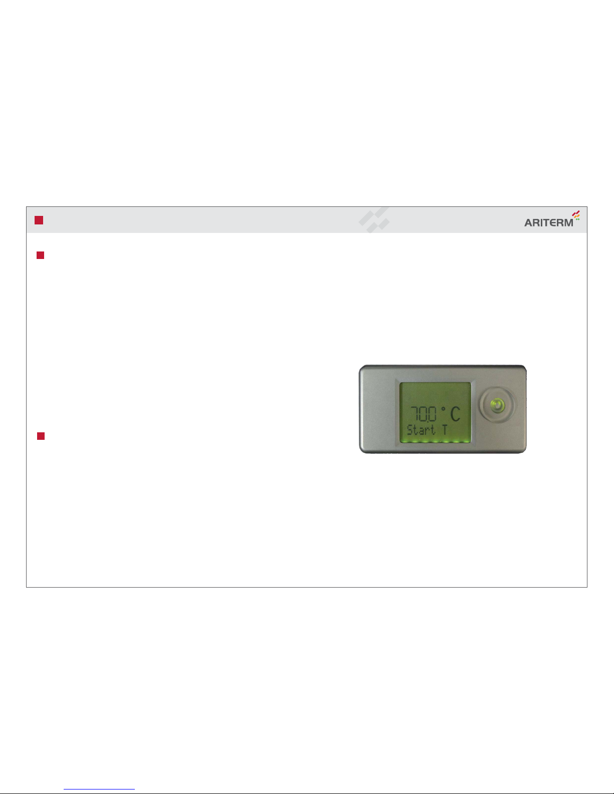
Main menu
Start? (Stop?) - Confirm by pressing once to start (stop).
Start T - Press to select and adjust desired start temperature.
Stop T - Press to select and adjust desired stop temperature.
Usermenu - Press for Usermenu.
Back - Press for display.
Usermenu (Användarmeny)
Settings
SetCode (021)
Settings - Press for Settings.
Service - Menu for authorised service technicians.
View - Press for Display menu
(See levels, operating time, programme version etc.)
Clockset - Set date and time.
Back - Press for main menu.
Service - Menu for authorised service technicians.
Ign dose - Adjust the pellet amount at ignition.
TstlDose - Test the pellet amount at ignition.
FeedHI - Adjust the pellet amount at high output.
FeedLO - Adjust the pellet amount at low output.
FeedMIN - Adjust the pellet amount at minimum output.
Air HI - Adjust fan at high output.
Air LO - Adjust fan at low output.
Air MIN - Adjust fan at minimum output.
HI 1/0 ? - Activate high output.
LO 1/0 ? - Activate low output.
MIN 1/0 ? - Activate minimum output.
Default? - All the values are reset to factory settings here.
Language - Select language.
Back - Press for Usermenu.
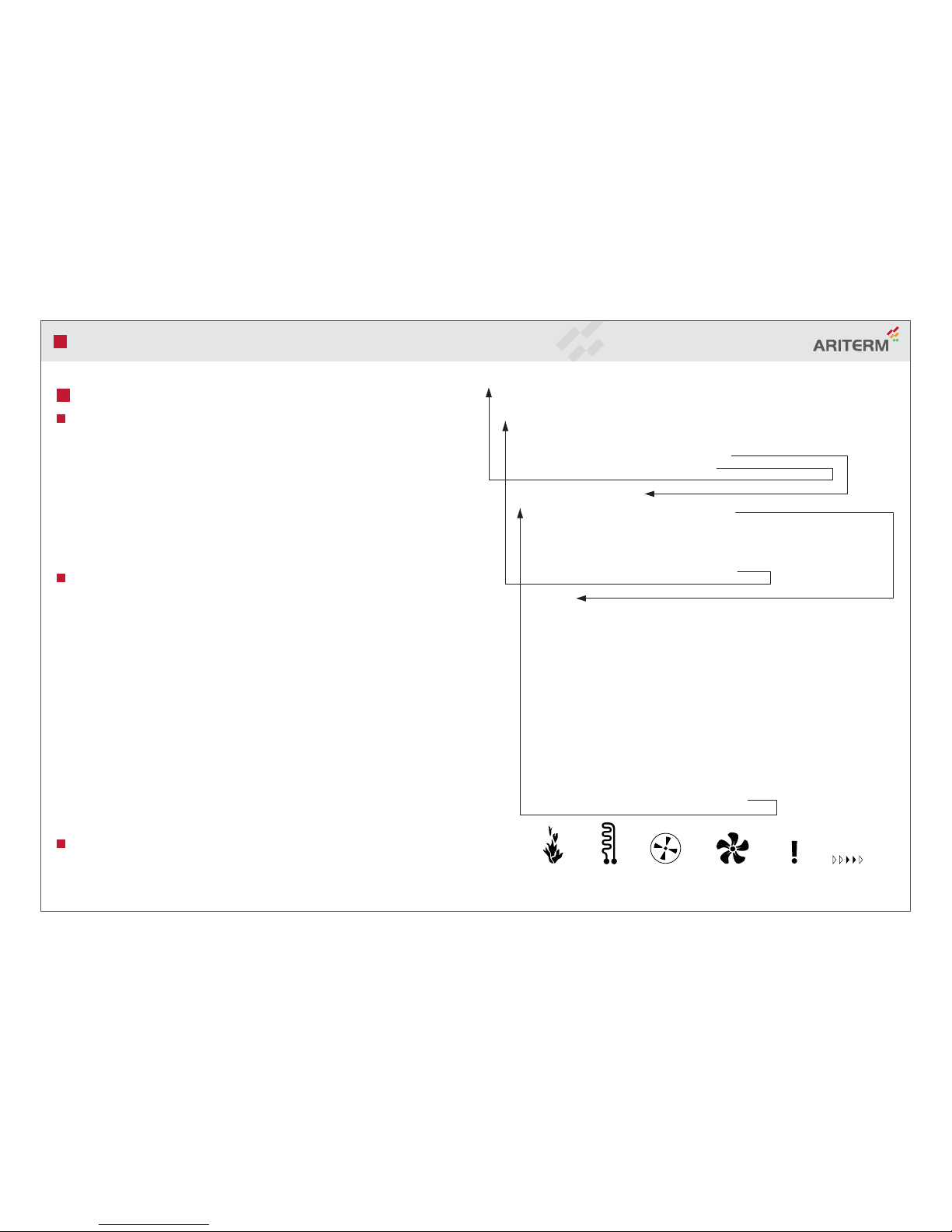
Flame
Indicated
Firing element
Activated
Feeder motor
Activated
Combustion fan
Activated
Fault function
Indicated
Burner in
operation

RC
PELLET STOKER KMP PX22
6G>I:GBHL:9:C67 Installation Instructions - 2010.06.22 - 7/16
Storage tank
Using a storage tank
The larger water volume achieved with a storage tank makes the stoker running
in longer intervals, thus giving higher efficiency.
However, the cost of installing a new storage tank is normally not profitable
due to the extremely high thermal efficiency of the KMP stoker.
Installation on a boiler system using a storage tank
If there is a calorifier or a shunt valve in the boiler, the temperature sensor
should always be attached directly to the boiler, preferably in an immersed tube.
When the boiler and the tank are in direct-cycle, the water temperature should
not be below 60˚C when the stoker starts, otherwise condensation may lead to
corrosion of the boiler body.
If the calorifier and shunt valve is situated in in the tank, the temperature sensor
can alternatively be placed on the tank, this leading to longer running intervals,
thus minimizing the number of starts and stops.
Placing the temperature sensor on the tank
If the temperature sensor is to placed on the storage tank, the charging pump
system must have capacity enough to cool the boiler off sufficiently.
Boiler temperature must not exceed 95˚C before the tank temperature is about
80˚C (recommended temperature) and the stoker stops.
The cut-out thermostat must always be attached to the boiler!
Two temperature sensors can be used with PX22. Simply connect two sensors
via our junction box (accessories, art.no 1599) to the burner’s temp. sensor
connector. Then an authorised installer adjusts the start, stop and alarm temp.
in the Service menu.
Boiler with PX22 and accumulator tank with solar panels.

PELLET STOKER KMP PX22
6G>I:GBHL:9:C67 Installation Instructions - 2010.06.22 - 8/16
Pellet retarder - feeder pipe
When the pellets are extremly hard
and/or the hose to the feeder pipe is
unusually long the pellets occationally
fall out of the burner. To prevent this
you could mount the pellet retarder.
Unscrew the screw in the front of the
feeder pipe. The pellet retarder mounts
with a screw from the outside.
(RXS 4,2 x 9,5).
The local chimney sweep sweeps the chimney once or twice a year – this is usually
notified at least a week beforehand. Ensure that the burner is switched off in good
time prior to the visit so that the burner and boiler have time to cool down.
Safety systems
The PX22 stoker meets all current safety regulations and standards.
There are two separate safety systems to avoid fire and hot gases going backwards:
a slooping stainless steel tube for the pellet feeder, and a cut-out thermostat on the
tube. These safety systems are independent of the electronic control system and
therefore cannot be disturbed by outer causes as for instance lightning.
A third safety component is the flame sensor, which indicates whether the fuel level
in the burner rises to a non-permitted level, or if cleaning is not carried out and the
burner pipe has too high a level of residual products.
In this case, the display shows in which operating mode the flame stopped being
indicated and stops as follows:
ErrStart - Operational stoppage at ignition.
ErrLow - Operational stoppage in low output mode.
ErrHigh - Operational stoppage in high output mode.
GOutStrt - Flame indicated at ignition but not in operation.
Resetting cut-out thermostat
The burner has overheat protection on the fall pipe, which deploys at 75˚C.
If it deploys, Errsafe appears in the display.
1. Disconnect the cords from the burner.
2. Unscrew the two screws from the cut-out thermostat protective cover,
remove cover.
3. Push botton on cut-out thermostat until it clicks.
4. Reassemble the protective cover.
Maintenance
The stoker is cleaned by raking out the ashes inside, wich must be done once a
week during the cold season. Otherwise a cleaning every other week is sufficient.
At these occasions the boiler also should be rinsed from ashes.
Ashes and soot inside the boiler can set back the efficiency dramatically.
Note! If the boiler previously has been fired with wood there’s a risk of soot and
taar getting loose and choke up the flue pipes and even the chimney. Check and
rinse if needed when rinsing the stoker for the first two months after installation.
The burner must be dismantled at least four times per year.
The outer and inner burner tubes should be separated and cleaned from sintered
ashes. Dismantle by loosing four screws on the front of the stoker.
Note that all cables have to be unplugged before removing the cover.

2
2
4
5
PELLET STOKER KMP PX22
6G>I:GBHL:9:C67 Installation Instructions - 2010.06.22 - 9/16
NOTE!
All work as described in the following text must be done by a qualified
person.
Changing the ignition element
1. Remove the burner cover by removing the two nuts and screws that hold the
cover in place and then pull the cover backwards.
2. Remove the two screws at the side of the bottom and fold the bottom plate
down.
3. Disconnect the firing element’s cables from their terminals (2 x blue).
4. Remove the two screws on the bottom, under the stoker.
5. Remove the screw that holds the element and pull out the element from its pipe.
6 Replace the element.
7. Refit in reverse order.
8. Ensure that the firing element is slid forward towards the inner pipe.
Changing light sensor
1. Disconnect all three cables on the stoker.
2. Remove the burner cover by removing the two nuts and screws and pull the
cover back.
3. Disconnect the edge connector from the control circuit board and pull out
the sensor from its hole to the right of the fan.
4. Push the new sensor into the hole until it gets stuck. Be sure to align it
perpendicular to the surface. Connect the edge connector and reinstall the
burner cover.
NOTE!
When an ignition failure occurs, don’t open the hatch until the combustion
chamber is properly ventilated!
Fig. 6 Ignition element

PELLET STOKER KMP PX22
6G>I:GBHL:9:C67 Installation Instructions - 2010.06.22 - 10/16
Troubleshooting and repair
Fault Cause What to do
The burner stops,
Fault code ErrSafe
The burner stops,
Fault code ErrStart
UÊÊ /iÊLÕÀiÀÊ>ÃÊÛiÀi>Ìi`°
UÊÊ /iÊLÕÀiÀÊ>ÃÊÌḚ̂Ê
Clean the burner and boiler.
Reset the fall pipe’s overheat
protection.
Check the pellet supply and the
starter dose “Ign dose”.
The burner stops UÊ /iÊLÕÀiÀÊ>`ÉÀÊLiÀÊ
need(s) sweeping.
Clean the burner and boiler.
The burner stops,
Fault code ErrLow
UÊÊ /iÊLÕÀiÀÊ>ÃÊ}iÊÕÌÊÊ
low output mode.
Check the pellet supply and the
“Feed LO” and “Air LO” settings.
The burner stops,
Fault code ErrHigh
UÊÊ /iÊLÕÀiÀÊ>ÃÊ}iÊÕÌÊÊ
high output mode.
Check the pellet supply and the
“Feed HI” and “Air Su” settings.
The burner stops,
Fault code GOutStrt
UÊÊ /iÊLÕÀiÀÊÌÊLÕÌÊÌiÊÜiÌÊ
out during pre-operation.
Check the pellet supply and the
“Feed SU” and “Air Su” settings.
(ServCode)
The burner stops,
Fault code ErrorIgn
UÊÊ /iÊwÀ}ÊiiiÌÊÃÊÌÊ
drawing any power.
Check the connections to the firing
element (120 - 145 Ohm) or replace
the firing element.
The burner stops,
Fault code Tempsens
The burner stops from
time to time and with-
out any visible cause.
UÊÊ /iÊVÌÀÊVÀVÕÌÊL>À`Ê>ÃÊÊ
contact with the temp. sensor.
UÊÊ >ÞÊLiÊ`ÕiÊÌÊÌÊ>À}iÊÀÊ
strong variations in vacuum in
the chimney, or fuel feed fault.
The temperature sensor circuit
may be broken by the external
thermostat or switch. If not, check
the connections to the temp. sensor
or replace
Contact your authorised installer for
overhauling and any installation of
draft inhibitors.

1
2
3
4
5
6
7
4
11 12
13 14
15
16
10
17
18
19
20
22
35
24
25
26
27
29
15
30
31
32
34
37
28
33
23
21
9
8
36
29
PELLET STOKER KMP PX22
6G>I:GBHL:9:C67 Installation Instructions - 2010.06.22 - 11/16
Exploded view / Technical data

PELLET STOKER KMP PX22
6G>I:GBHL:9:C67 Installation Instructions - 2010.06.22 - 12/16
Technical data
Dimensions outside boiler (b x h x d).. 220 x 250 x 300 mm
Dimensions inside boiler (Ø x l)................... Ø156 x 200 mm
Efficiency .............................................................circa 95%
Output high output mode......................................... 20 kW
Output low output mode..............................approx. 10 kW
Voltage................................................................. 230 VAC
Power consumption (mean under power)....................40 W
Weight ...................................................................... 12 kg
Accessories and fittings
UÊ £ÎäÊ "ÛiÀi>ÌÊVÕÌÕÌÊÌiÀÃÌ>ÌÊ*
UÊÊ £{äÇÊ -ÕëiÃÊV>ÊÊ
UÊÊ Ó{Ó{ÊÊ ÃÊVÞViÊvÀÊÃÕV}ÊÕÌÊ>Ã
UÊÊ £ÓäÊ VÀÊ«iiÌÊÃÌÀ>}i
UÊÊ £ÓÈxÊÊ ÕiÊÌiÀiÌiÀ
UÊÊ £ÎÇÎÊ *iiÌÊÃÌÀ>}iÊÎääÊ
UÊÊ £Óä£ÊÊ À>vÌÊÀi}Õ>ÌÀÊ/8ÊÜÌÊy>}i
UÊÊ n£änÊÊ >ÃÃÊwLÀiÊ}>ÃiÌÊ(£xÊ
UÊÊ £ÎÈÊÊ >ÊÃiÊ`>iÌiÀÊÇäÊÉ
UÊÊ £ÎnÈÊÊ `>«ÌiÀÊvÀÊ«iiÌÊÃiÊÇäÈÈ
UÊÊ £ä£ÓÊ ii`Ê«iiÌÊvii`iÀÃ
UÊÊ £ÎÓÊÊ i«Êvii`ÊVÕÌiÊ
UÊÊ £äÓÊÊ iÀÊV«ÀiÃÃi`Ê>ÀÊVi>}
UÊÊ £xÊÊ ÕVÌÊLÝÊVVÕÕ>ÌÀÊÌ>ÊVÌÀ®
Component parts
No. Part no. Designation
1. 8152 Screw MF6S M6 x 12 untr.
2. 1157 Outer pipe PX2X
3. 1341 Carriage plate PX21
4. 8117 Screw MLC6S M6 x 16 untr.
5. 8148 Nut M6M M6 FZB
6. 2585 Gasket rope 10 mm black coated
7. 1150 Docking flange PX2X
8. 8231 Dome nut M6 FZB
9. 3120 Insulation
10. 1493 Connector plate PX22
11. 1151 Plate for docking flange PX2X
12. 1451 Flame detector for burner Cc05
13. 8133S crew MLC6S M6 x 10 untr
14. 1288 Fall pipe with flange PX2X
15. 1566 Spacer screw Steel M4x5 Px22
16. 1490 Electrical bracket PX22
17. 1133 Overheat protection fall pipe
18. 1156 Chute OH PX2X
19. 1555 Burner cover PX22, stainless
20. 1586 Control circuit board PX22
connection
21. 8352 Apparatus inlet with net filter
22. 8112 Apparatus outlet black
23. 1182 Trafo PX2X
24. 1452 Internal wiring temp. sensor Px
25. 1245 Fan PX2X
26. 8113 Rubber grommet 3.5/7/12
No. Part no. Designation
27. 1492 Sweep rear cover PX22
28. 1593 Terminal housing 10 pin
VAL-U-LOK
29. 1620 Screw K6S M4 x 4
30. 1570 Firing element pipe PTC
31. 1574 Firing element PTC
32. 1567 Firing bracket PTC
33. 1491 Bottom Rear cover PX22
34. 1158 Inner pipe PX2X
35. 8322 Apparatus outlet grey
36. 1188 Holder for firing element
37. 1610 Plastic plug 15.9 hole

PELLET STOKER KMP PX22
6G>I:GBHL:9:C67 Installation Instructions - 2010.06.22 - 13/16
Assemble description
1 Slacken off the screws holding the inner pipe.
2 Chose a suitable position for the feeder tube and fix it by means of the attached
screws.
CAUTION: the lower edge of the pipe must enter the inlet hole of the inner tube.
3 Place the cut out-thermostat in the open stainless steel box, fasten the box to the
feeder tube with the two screws, the metal side of the thermostat facing towards
the tube.
4 Undo the two screws on the bottom side of the burner. Push them forward in the
slots until the ignition element touches the inner tube. Tighten the screws.
The burner is now ready for installation.

PELLET STOKER KMP PX22
6G>I:GBHL:9:C67 Installation Instructions - 2010.06.22 - 14/16
Warranty
For warranty issues Ariterm Sweden AB refers to our local Distributor.

PELLET STOKER KMP PX22
6G>I:GBHL:9:C67 Installation Instructions - 2010.06.22 - 15/16
Declaration of conformity

PELLET STOKER KMP PX22
6G>I:GBHL:9:C67 Installation Instructions - 2010.06.22 - 16/16
If these instructions are not followed during installation, operation
and maintenance, the obligations of Ariterm Sweden AB under the warranty
regulations are no longer binding. Ariterm reserve the right to alter any details
and specifications without prior notice.
Ariterm Sweden AB
Flottiljvägen 15, SE-392 41 Kalmar
www.ariterm.se
Table of contents
Other Ariterm Pellet Stove manuals