PelPro Pellet Stove • 7083-801F • 04/21 PelPro Pellet Stove • 7083-801F • 04/21pelprostoves.com pelprostoves.com
89
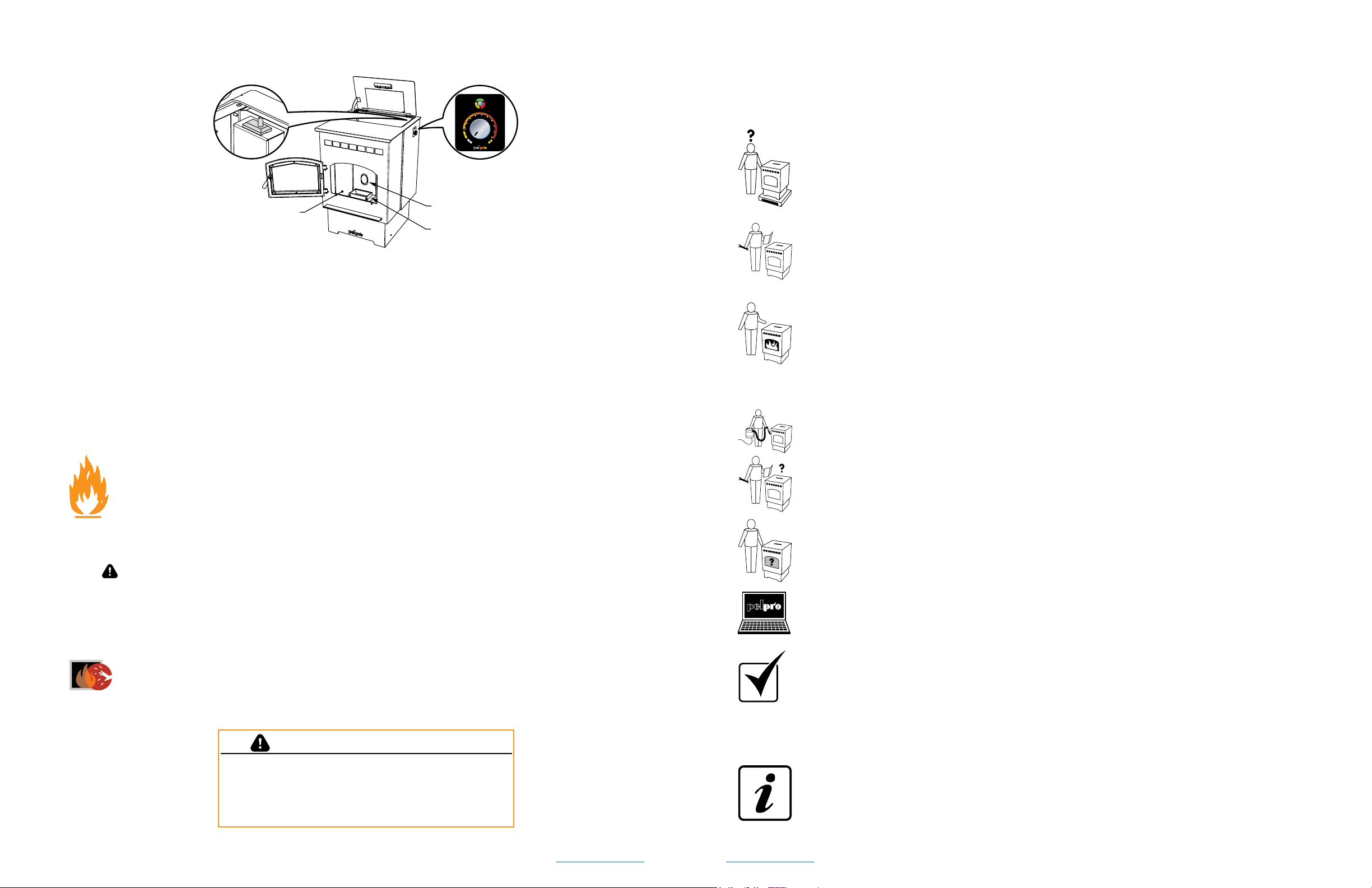
Installing Your Stove
Installing Your Stove
Installing Your Stove Installing Your Stove
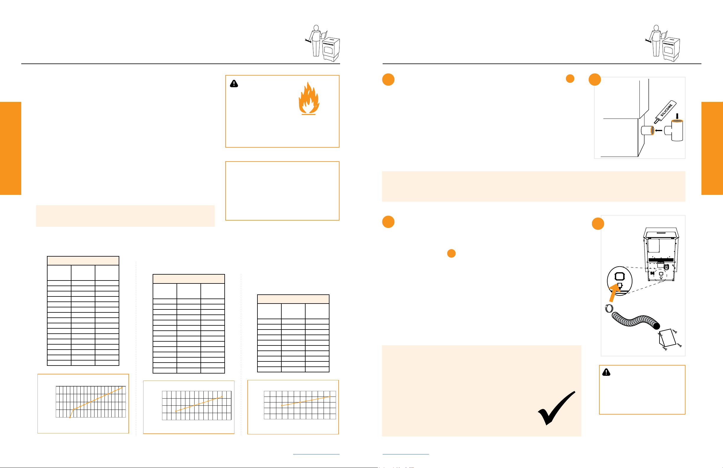
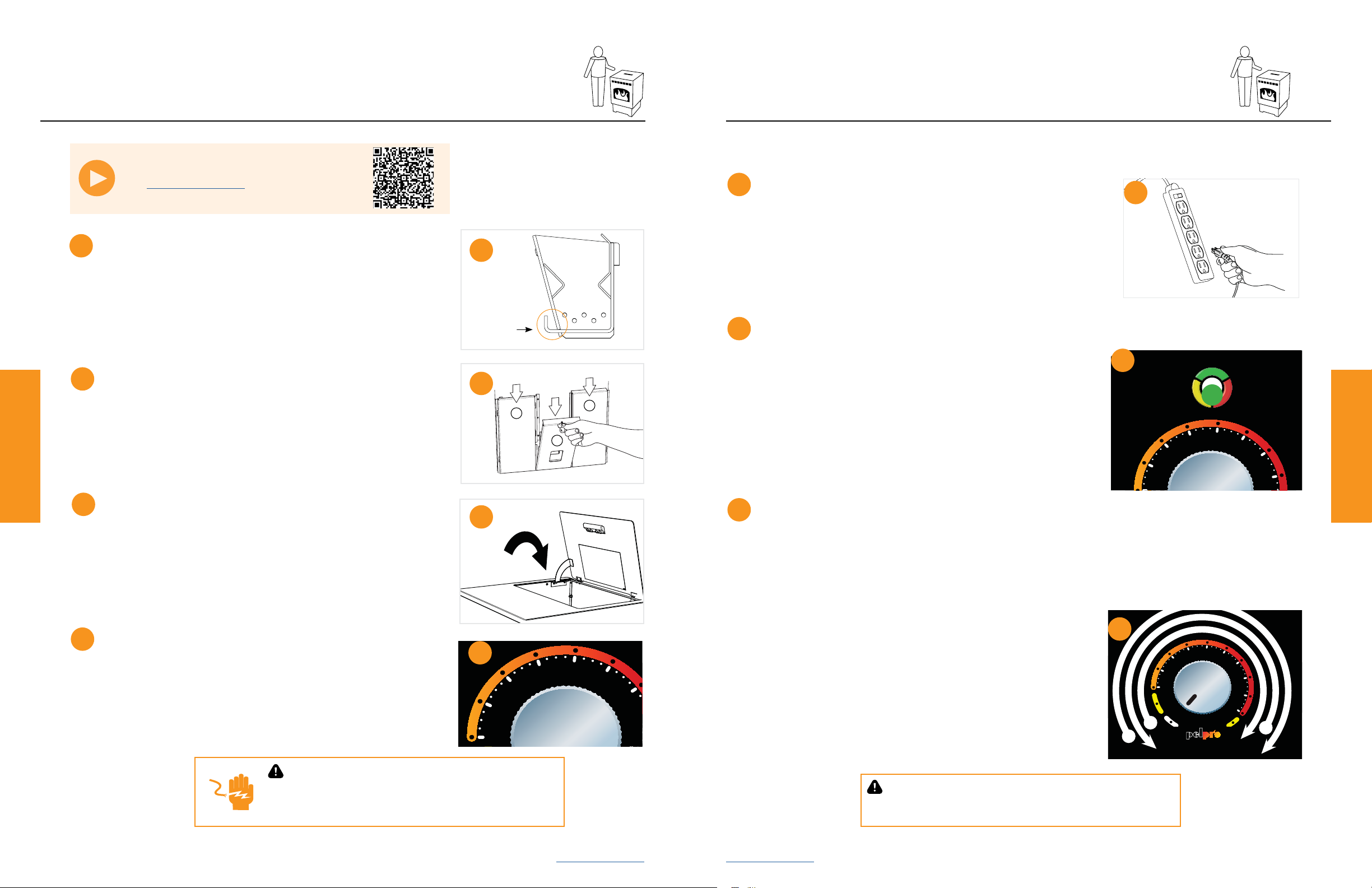
Vent Termination Clearances Placing Your Stove
Vent Termination Clearances
CONFIDENTIAL PROPERTY OF HEARTH & HOME TECHNOLOGIES INC.
DRAWN BY: SCALE: MATERIAL:
SHEET:
PART NUMBER:
THIS PRINT IS CHECKED AND CONTROLLED BY THE ENGINEERING
DEPARTMENTS OF HEARTH & HOME TECHNOLOGIES INC.
DATE BY
06/19/13 MCW
06/05/14 MCW MCW 1:1 SEE NOTE
1 OF 1
7083-167
UNLESS OTHERWISE SPECIFIED DIMS ARE INCHES[MM] & : TOLERANCES ARE: (2) PLACE DEC : ± 0.03 (3) PLACE DEC: ± 0.005 ANGLE: ± 2° FRACTION: ± 1/16
OUTSIDE MATERIAL.
1. MATERIAL: NON-ANODIZED ALUMINUM 0.020 THICK
73351 9/3/2013 WPK
74013 01/07/14 WPK
75292 06/05/14 MCW
Remove / Supprimer / Quitar
2. Deje enfriar la unidad antes de realizar cualquier trabajo de mantenimiento.
The appliance will automatically maintain the desired comfort level and shut down when level has
L'appareil passera automatiquement maintenir le niveau de confort désiré et arrêter lorsque le
El aparato mantendrá automáticamente el nivel de confort deseado y se cerrará cuando el nivel se ha
** The appliance will run continuously until switched to OFF or COMFORT LEVEL mode.
L'appareil fonctionne de façon continue jusqu'à ce que passe en mode OFF ou NIVEAU DE CONFORT.
El aparato funciona continuamente hasta que cambia al modo OFF o NIVEL DE CONFORT.
REV REVISIONS
A RELEASED 72901
B ADDED WWW.PELPROSTOVES.COM 75290
NOTE:
1. MATERIAL: NON-ANODIZED ALUMINUM 0.020 THICK
2. BACKGROUND: SILVER
3. COPY: BLACK
4. ADHESIVE: 3M #468 PERMANENT ACRYLIC
5. TEMPERATURE RATING: -50°F TO 350°F
C BACKGROUND AND COPY NOTE UPDATD
D GROUPED LANGUAGES, REMOVED PHONE NUMBER
Parada
1. Gire el dial de control en la posición OFF.
2. Deje enfriar la unidad antes de realizar cualquier trabajo de mantenimiento.
* The appliance will automatically maintain the desired comfort level and shut down when level has
been achieved.
L'appareil passera automatiquement maintenir le niveau de confort désiré et arrêter lorsque le
niveau a été atteint.
El aparato mantendrá automáticamente el nivel de confort deseado y se cerrará cuando el nivel se ha
logrado.
** The appliance will run continuously until switched to OFF or COMFORT LEVEL mode.
L'appareil fonctionne de façon continue jusqu'à ce que passe en mode OFF ou NIVEAU DE CONFORT.
El aparato funciona continuamente hasta que cambia al modo OFF o NIVEL DE CONFORT.
1
2
1
2
A
D.
B
L
C
K
J
B
I
H
G
F
Clearances
A 12” Clearance above grade, veranda porch, deck or balcony (Including vegetation and mulch)
B12” Clearance beside or below any windows or doors that open
12”* Clearance above any window or door that opens
C 18” Vertical clearance to ventilated soft located above the terminal within a horizontal distance of 2 feet from
the center line of the terminal
D 12” Clearance to an outside corner wall
F12”,
48” no outside air kit Clearance to a non-mechanical air supply inlet to the building or a combustion air inlet to any other Stove
G 36” Clearance to a mechanical air supply inlet
H 84”** Clearance above a paved sidewalk or paved driveway located on public property
I 12”** Clearance under a veranda, porch, deck or balcony
J 12” Clearance above the roof
K 24” Clearance from an adjacent wall including neighboring buildings
L
36” within a height of 15
feet above the meter /
regulator assembly
Clearance to each side of center line extended above natural gas or propane meter / regulator assembly or
mechanical vent
*Recommended to prevent condensation on windows and thermal breakage. **This is a recommended distance. For additional requirements check local codes.
NOTICE:
Do NOT terminate vent:
• In any location that will allow ue gases or soot
from entering or staining the building
• In any location which could create a nuisance or
hazard
• In any enclosed or semi-enclosed area such as
a carport, garage, attic, crawl space, under a
sun deck or porch or narrow walkway
• Closely fenced area, or any location that can
build up a concentration of fumes such as a
stairwell, covered breezeway, etc.
NOTICE:
Do NOT terminate below an air inlet.
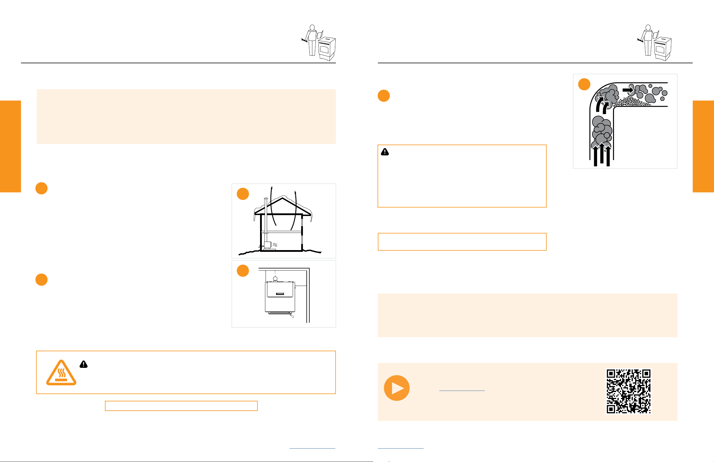
• It is recommended that at least 60” (1.52m) of
vertical pipe be installed when Stove is vented
directly through a wall—this will create a natural
draft, which will help prevent the possibility of
smoke or odor venting into the home during a
power outage
• It will also keep exhaust from causing a nuisance
or hazard by exposing people or shrubs to high
temperatures
• The safest and preferred venting method is to
extend the vent vertically through the roof or
above the roof
Notice: Be careful to protect the bottom of the Stove and oor surfaces when moving the Stove. Bottom edges
of Stove are sharp and can scratch surfaces.
Notice: Clearances may only be reduced by means approved by the regulatory authority having jurisdiction.
USA Hearth Pad Requirements Inches mm
A Sides 2 51
B Back 2 51
C Front 6 152
Non-combustible oor protection extending beneath the ue pipe is required with horizontal venting or under the top vent adapter
with vertical installation.
*Non-combustible oor protection must extend 2 inches (51mm) beneath the ue pipe when installed horizontal venting or under
the top vent adapter with vertical installation. CANADA REQUIRED, USA RECOMMENDED.
Canada Hearth Pad Requirements Inches mm
A Sides 8 203
B Back 2 51
C Front 6 152
Hearth pad minimum requirements:
B*
A
C
A
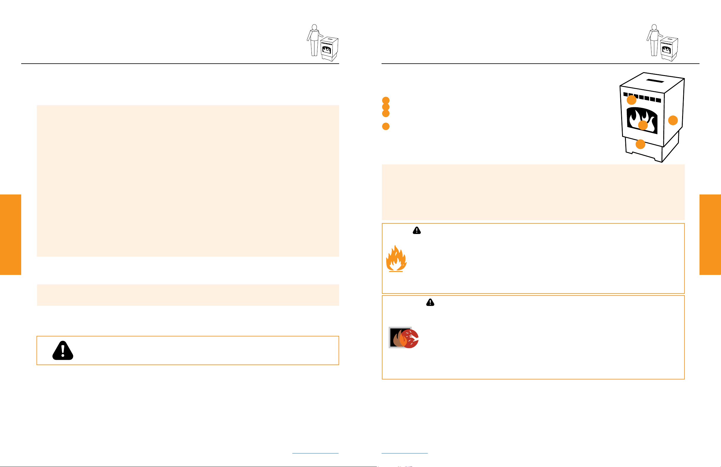
Placing Your Stove
It is necessary to install EMBER PROTECTION; a Type I oor protector for this Stove.
The Floor protector must be non-combustible material, extending beneath Stove
with a minimum of 6
inches
(152mm) in front of glass and 6 inches (152mm) to both sides of the fuel loading door. Open the door and
measure 6 inches (152mm) from the side edge of the opening in the face of the Stove.