Arlyn Scales ARL-BR-IS Series User manual

Contents
1. OVERVIEW..........................................................................................................................................................................................3
2. FACTORY MUTUAL APPROVAL AND INTRINSIC SAFETY .....................................................................................................................3
3. DESCRIPTION......................................................................................................................................................................................3
3.1. Introduction..............................................................................................................................................................................3
3.2. ARL-BR-IS Series Barriers..........................................................................................................................................................3
4. SAFETY CHECKS ..................................................................................................................................................................................4
5. WIRING CONNECTIONS......................................................................................................................................................................4
5.1. Overview ..................................................................................................................................................................................4
5.2. Signal Connections ...................................................................................................................................................................4
5.2.1. Precautions ..........................................................................................................................................................................4
5.2.2. Wiring...................................................................................................................................................................................5
5.2.3. Power Supply Connections, Grounding and General Considerations ..................................................................................5
6. ENTITY PARAMETERS (RATINGS)........................................................................................................................................................6
7. MAINTENANCE...................................................................................................................................................................................6
7.1. General Considerations ............................................................................................................................................................6
7.2. Routine Inspection ...................................................................................................................................................................6
8. LIMITED WARRANTY ..........................................................................................................................................................................7
9. CONTROL DRAWINGS ........................................................................................................................................................................7

1. OVERVIEW
This instruction manual contains all information needed to install and maintain the ARL-BR-IS range of safety barriers. Indicated
below are the manual’s current revision and number of pages. Please check this manual and its control drawings for missing pages.
The installation cannot continue unless all pages are present.
Table 1: List of Controlled Documents as part of this manual.
Document
Description
Number of Pages
Document #5902
ARL-BR-IS Series Instruction Manual
Control Drawing #5210
ARL-BR-IS General Dimensions
1
Control Drawing #5211
ARL-BR-IS Barrier Label Drawing
2
Control Drawing #5213
ARL-BR-IS Installation and Wiring Diagram
4
Please check Section 5 for a list of safety checks that need to be done when using the ARL-BR-IS series Safety Barriers for Intrinsically
Safe (IS) interfaces between safe and hazardous areas. This section must be consulted each time before beginning any installation of
the barriers.
It is assumed that all necessary system design, specification and engineering factors have been taken into account before installation
of the barriers. Please refer to the above documentation listed to assist in pre-planning your installation. The documents consist of
theory, design, application, specifications and certifications of the safety barrier.
If not supplied with the product, these publications are available either from our website (www.arlynscales.com) or on request from
our factory.
2. FACTORY MUTUAL APPROVAL AND INTRINSIC SAFETY
The ARL-BR-IS Safety Barrier has been rated intrinsically safe by Factory Mutual only if the installation is performed by a qualified
technician who conforms to the guidelines described in this manual. Consult the chapter titled “Installation and Wiring” along with
the control drawings in the back of this document for information pertaining to the installation and wiring of the approved barrier.
This system, when installed in accordance with this document, has been approved by Factory Mutual for use in the following
classified areas:
Associated Intrinsically Safe Apparatus providing connections for use in Class I, II, III, Division 1, Groups A, B, C, D, E, F and G; Class
I, Zone 0, Aex ia IIC Ga; in accordance with Control Drawing No. 5213; Hazardous (Classified) Locations. Associated Nonincendive
Apparatus providing connections for use in Class I, II, III Division 2, Groups A, B, C, D, F, and G; in accordance with Control Drawing
No. 5213; Hazardous (Classified) Locations
3. DESCRIPTION
3.1. Introduction
The ARL-BR-IS series set of Safety Barriers are anywhere from 1- to 5-channel devices that use intrinsically safe explosion proof
techniques to pass electrical signals between safe and hazardous areas while limiting energy transfer to a level that cannot ignite
flammable atmospheres.
When the ARL-BR-IS series of safety barriers are connected in series with wiring entering any hazardous area, these barriers prevent
explosions in all normally occurring explosive atmospheres –including mixtures of air with flammable gases, vapors, dusts and fibers
- if a fault or faults develop in the safe area.
3.2. ARL-BR-IS Series Barriers
The series is based on the most common uses in dealing with a very specific set of entity parameters. They are primarily designed to
work with Arlyn’s MKE-5-IS(-C) Intrinsically Safe Weighing System and Arlyn’s Intrinsically Safe load cells. However, these barriers are

built in such a way that they can also handle general application configurations as long as they fall within the specified entity
parameters.
4. SAFETY CHECKS
The following checks should be carried out to ensure the safety of barrier installation. Use the checklist below to prevent important
safety consideration being overlooked when installing, commissioning, modifying or servicing installation of ARL-BR-IS Series of
safety barriers. Check the list before and after the safety barrier is installed. Each item in the list is cross-referenced to the
appropriate section in the manual.
For Factory Mutual based installations see FM certification information.
Table 2: Installation Checks
Item
Installation Check
1
Before beginning installation, check that the safety documentation confirms that the proposed system is fully certified (if
applicable) and complies with the recommendations contained in the relevant sections of IEC 60079-14 for the gas group,
temperature classification and area classification required.
2
Make sure the barriers are of the correct type and polarity as specified in the safety documentation.
3
Make sure the barriers are mounted the right way around and are properly attached so that the necessary earth contact is
made securely in accordance with the safety documentation and in compliance and recommendations of IEC 60079-14.
4
Inspect all the connected cables carefully between the barriers and the hazardous area equipment. Make sure that the
cables are the type specified in the safety documentation and that they are connected to the correct terminals.
5
Make sure all hazardous area cables are well secured and are segregated from all other cables.
6
Make sure all hazardous area cable parameters for hazardous area circuits are not exceeded (see relevant control
drawings).
7
Make sure all hazardous area cables and cable screens are terminated correctly, the latter preferably via the earth
“ground lug” on the hazardous side of each barrier.
8
Make sure all unused hazardous area cables are safely connected to earth ground.
9
Make sure all hazardous area energy storing devices are independently and appropriately certified.
10
Inspect all tagging or identification labels and make sure they relate to the correct barrier types, polarities and circuit loop
numbers.
11
Inspect carefully all cables connected to the safe area equipment and make sure they are connected to the safe area
terminals of the barriers.
12
Make sure all barriers are protected adequately against moisture, dust, dirt, vibration, excessive temperatures, physical
damage and unauthorized modifications.
5. WIRING CONNECTIONS
5.1. Overview
The ARL-BR-IS Series barriers come in 6 different models, but its body form is the same for all six models. Depending on the model,
only certain terminals will be available on the barrier for wiring.
The terminals are positioned in clearly marked designations for hazardous and safe area connectivity.
5.2. Signal Connections
Before connecting any signal lines, the following precautions must be taken to ensure safety of the barrier installation.
5.2.1. Precautions
Clearly designate hazardous area and safe area cabling as defined by relevant codes of practice and route cabling to the barriers
through clearly separated and identified conduits or trunking. Deal with spare cable cores or screens as described later in this
manual.

Before making any signal connections from the hazardous are, make sure any Intrinsically Safe energy-storing devices (i.e. devices
not classified as “simple apparatus”) are certified as being compatible with the barriers to which they will be connected. Check also
that the connecting cables conform with the cable types specified by the safety documentation and that the maximum cable
parameters specified in the IS catalogue are not exceeded. In general, cable parameters are unlikely to present problems except in
installations where cables longer than 500 meters are called for in IIC applications.
5.2.2. Wiring
The following steps outline how to connect the signal line connections to an ARL-BR-IS Series Safety Barrier. Please note, in most
cases, the Barrier will come pre-wired using the recommended cable specifications so you do not have to perform these steps.
1. Unscrew the top 6 screws from the enclosure and remove the lid to access the barrier board inside it.
2. The barrier board will have clearly marked screw terminals for connecting the signal lines. For illustrations on how the barrier
terminals are mapped to their respective signal lines, please refer to page 2 of the ARL-BR-IS Series Datasheet (Doc #6200). Note
–Based on your barrier model, only certain terminal blocks will be populated on the board.
3. Pass your cable wire into the provided strain relief from the safe area. Do the same for the hazardous area.
4. Connect the wires as designated below depending on your barrier model type.
Table 3: Wiring Map
MODEL
SIGNAL EXAMPLES
SAFE AREA
HAZARDOUS AREA
Terminal Block
Pin
Terminal Block
Pin
ARL-BR-IS-PWR
5VDC Line (or less)
PWR-485 (P+)
1
PWR (P+)
9
GND
PWR-485 (P-)
2
PWR (P-)
10
ARL-BR-IS-LC
LC Excitation + (E+) or RS422 (A)
Loadcell-LC (E+)
5
LC-EXC (E+)
13
LC Excitation - (E-) or RS422 (B)
Loadcell-LC (E-)
6
LC-EXC (E-)
14
LC Signal + (S+) or RS422 (Y)
Loadcell-LC (S+)
7
LC-SIG (S+)
15
LC Signal - (S-) or RS422 (Z)
Loadcell-LC (S-)
8
LC-SIG (S-)
16
ARL-BR-IS-RS
RS-485 (A)
PWR-485 (A)
3
485 (A)
11
RS-485 (B)
PWR-485 (B)
4
485 (B)
12
ARL-BR-IS-PWR-RS
5VDC Line (or less)
PWR-485 (P+)
1
PWR (P+)
9
GND
PWR-485 (P-)
2
PWR (P-)
10
RS-485 (A)
PWR-485 (A)
3
485 (A)
11
RS-485 (B)
PWR-485 (B)
4
485 (B)
12
ARL-BR-IS-PWR-LC
5VDC Line (or less)
PWR-485 (P+)
1
PWR
9
GND
PWR-485 (P-)
2
PWR
10
RS422 (A)
Loadcell-LC (E+)
5
LC-EXC (E+)
13
RS422 (B)
Loadcell-LC (E-)
6
LC-EXC (E-)
14
RS422 (Y)
Loadcell-LC (S+)
7
LC-SIG (S+)
15
RS422 (Z)
Loadcell-LC (S-)
8
LC-SIG (S-)
16
5. Make sure all the connections are correct.
6. Screw the lid back onto the barrier enclosure using the previously removed screws.
7. Connect the Earth ground in the provided ground lug.
8. Remount the barrier as instructed in the previous sections.
5.2.3. Power Supply Connections, Grounding and General Considerations
Care must be taken that if the barriers are connected to the a safe are power supply, these connections must be made correctly. If
the internal fuse blows, it will destroy the ARL-BR-IS-Series barriers.
The barrier is equipped with a green ground lug. Use this ground lug to accomplish your IS ground requirements. Please refer to Doc
#5213 –Installation and Wiring Diagram for further details.

6. ENTITY PARAMETERS (RATINGS)
The following ratings apply for the ARL-BR-IS Safety Barrier.
ARL-BR-IS-PWR Entity/NIFW Output Parameters: Uo = 4.935V, Io = 1.7A, Po = 760mW, Co = 100uF, Lo = 12.3uH
ARL-BR-IS-LC Entity/NIFW Output Parameters: Uo = 5.715V, Io = 72mA, Po = 80mW, Co = 46uF, Lo = 6.8mH
ARL-BR-IS-RS Entity/NIFW Output Parameters: Uo = 5.715V, Io = 36mA, Po = 40mW, Co = 46uF, Lo = 27.4mH
ARL-BR-IS-PWR-RS Entity/NIFW Output Parameters: Uo = 6.135V, Io = 1.736A, Po = 850mW, Co = 34uF, Lo = 11.7uH
ARL-BR-IS-PWR-LC Entity/NIFW Output Parameters: Ut = 6.135V, It = 1.772A, Po = 850mW, Co = 34uF, Lo = 11.3uH
7. MAINTENANCE
7.1. General Considerations
Provided they are correctly installed and connected (as described in Sections 5 and 6 in this manual), and that the system they are
protecting are not themselves defective, barrier faults are highly unlikely to occur. Therefore, servicing of barrier installations
consists mainly of routine inspection and earth testing as described in this section.
More information about the maintenance of barrier installations is given in the Standards Document BS EN 60079-17.
7.2. Routine Inspection
At intervals not exceeding two years (more frequently for harsh environments), make a visual check of the barrier installation.
Personnel undertaking these checks should comply with all regulations relating to the safety of plant and personnel. Care must be
taken to prevent any inadvertent direct connection between hazardous- and safe area circuits and, at all times, the safety
precautions discussed in section 5 MUST be observed.
Check that:
a) Barriers are of the types and polarities specified in the safety documentation.
b) The barriers are attached securely and correctly Earth Ground to make sure that the earth connection is safe. If the barrier
came with the optional DIN rail mount, make sure that the barriers are mounted correctly according to that specification.
c) There are no apparent signs of damage or corrosion to the barriers, the plant earth connections, and if fitted, any earth rail
assemblies.
d) All hazardous area and safe area cable connections are made correctly and the terminals properly tightened.
e) Interconnecting cables are of the type and rating specified by the safety documentation and that they are not frayed or
otherwise damaged.
f) All earth returns and cable screens from the hazardous area are connected to earth through the barrier, a dummy barrier or
earth rail.
g) Visually examine the earth conductors and make sure they are not damaged in any way that their terminations are secure
and free from corrosion.
h) Using a low-voltage low-current test meter (i.e. a meter with an output not exceeding 3V and 50mA), measure the
resistance of the earth ground and the neutral star-point of the supply to make sure it doesn’t exceed 1Ω. Record the

reading and compare it with readings taken from previous inspections. A consistent reading repeated over a long period of
time is a reassuring sign indicating a sound earth return which is likely to remain so.
WARNING: Do not try to carry out a high-current earth resistance test unless it is confirmed by the authority in charge of the plant
that the plant is gas free.
8. LIMITED WARRANTY
Arlyn Scales warrants that your Arlyn Scales equipment and systems, when properly installed will operate per written specifications.
All systems and components are warranted against defects in materials and workmanship for a period of one year.
Arlyn Scales warrants that the equipment sold hereunder will conform to the written specifications authorized by Arlyn Scales. Arlyn
Scales warrants the equipment against faulty workmanship and defective materials. If any equipment fails to conform to these
warranties, Arlyn Scales will, at their option, repair or replace such goods returned within the warranty period subject to the
following conditions:
Upon discovery by Buyer of such nonconformity, Arlyn Scales will be given prompt written notice with a detailed explanation of the
alleged deficiencies.
Individual electronic components returned to Arlyn Scales for warranty purposes must be packaged to prevent electrostatic
discharge (ESD) damage in shipment.
Examination of such equipment by Arlyn Scales confirms that the nonconformity actually exists, and was not caused by accident,
misuse, neglect, alteration, improper installation, improper repair or improper testing; Arlyn Scales will be the sole judge of all
alleged non-conformities.
Such equipment has not been modified, altered or changed by any person other than Arlyn Scales. Arlyn Scales will have reasonable
time to repair or replace the defective equipment. The buyer is responsible for shipping both ways.
In no event will Arlyn Scales be responsible for travel time, or on-location repairs, including assembly or disassembly of equipment,
nor will Arlyn Scales be liable for the cost of any repairs made by others.
THESE WARRANTIES EXCLUDE ALL OTHER WARRANTIES, EXPRESSED OR IMPLIED, INCLUDING WITHOUT LIMITATION WARRANTIES
OF MERCHANTABILITY OR FITNESS FOR A PARTICULAR PURPOSE. ARLYN SCALES WILL NOT, IN ANY EVENT, BE LIABLE FOR
INCIDENTAL OR CONSEQUENTIAL DAMAGES
ARLYN SCALES AND BUYER AGREE THAT ARLYN SCALES SOLE AND EXCLUSIVE LIABILITY HEREUNDER IS LIMITED TO REPAIR OR
REPLACEMENT OF SUCH GOODS. IN ACCEPTING THIS WARRANTY, THE BUYER WAIVES ANY AND ALL OTHER CLAIMS TO WARRANTY.
SHOULD THE SELLER BE OTHER THAN ARLYN SCALES, THE BUYER AGREES TO LOOK ONLY TO THE SELLER FOR WARRANTY CLAIMS.
NO TERMS, CONDITIONS OR UNDERSTANDING, OR AGREEMENTS PURPORTING TO MODIFY THE TERMS OF THIS WARRANTY SHALL
HAVE ANY LEGAL EFFECT UNLESS MADE IN WRITING AND SIGNED BY A CORPORATE OFFICER OF ARLYN SCALES AND THE BUYER.
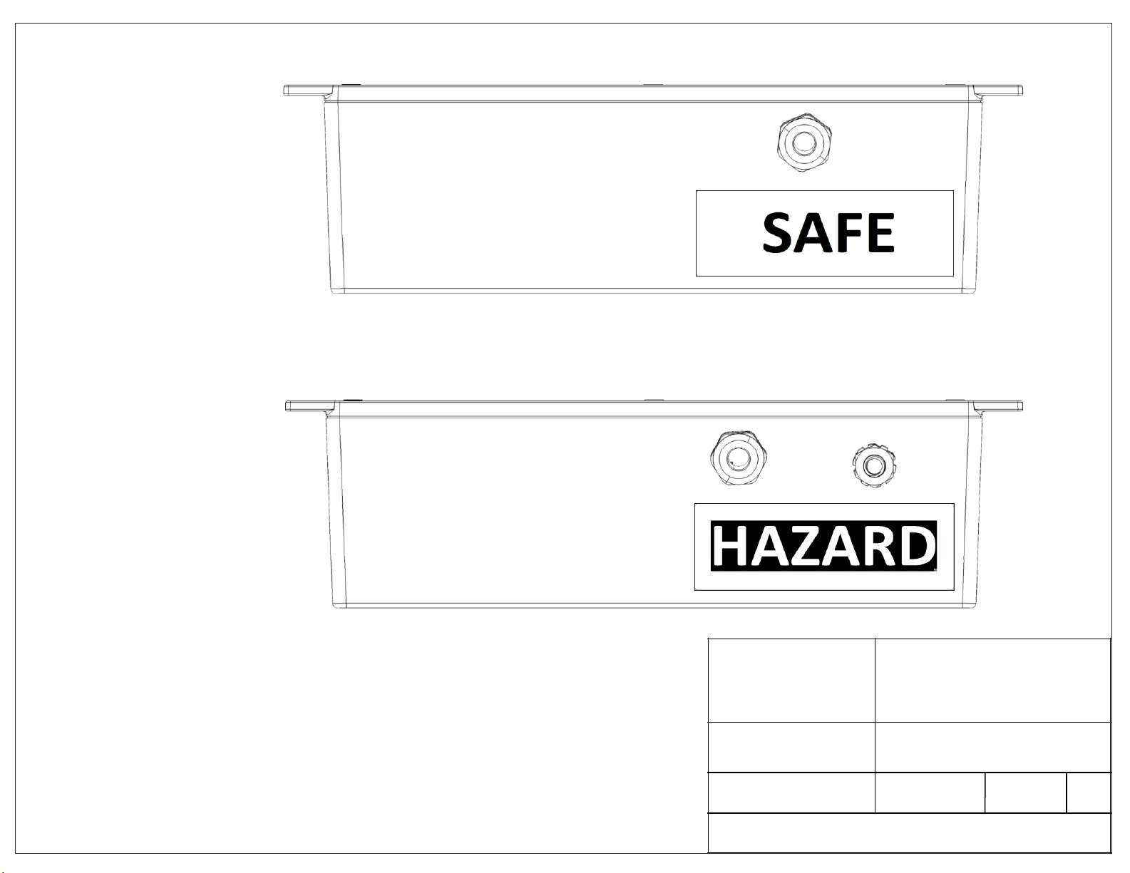
9. CONTROL DRAWINGS
The following drawings, required for the installation of the ARL-BR-IS Safety Barrier, are listed below and are included on the
following pages.
Doc No Title
5210 ARL-BR-IS General Dimensions
5211 ARL-BR-IS Label Drawing
5213 ARL-BR-IS Installation and Wiring Diagram

8.55
1.72
0.83
0.57
4.45
3.31
2.51
2.40
0.76
0.68
0.68
2.53
2.40 8.11
3.54
0.33
R0.06 TYP
0.20 TYP
A A
B B
C C
D D
8
8
7
7
6
6
5
5
4
4
3
3
2
2
1
1
5210
SHEET 1 OF 1
UNLESS OTHERWISE SPECIFIED:
DWG. NO.
NAME
DATE
CHECKED
DRAWN
DIMENSIONS ARE IN INCHES
PROPRIETARY AND CONFIDENTIAL
THE INFORMATION CONTAINED IN THIS
DRAWING IS THE SOLE PROPERTY OF
CIRCUITS AND SYSTEMS, INC.
DBA ARLYN
SCALES.
ANY
REPRODUCTION IN PART OR
AS A WHOLE
WITHOUT THE WRITTE
N
PERMISSION OF
CIRCUITS AND SYSTEMS,
INC.
DBA ARLYN SCALES
IS PROHIBITED
.
1.00
DIEGO 10/4/2019
MMK 10/4/2019
CIRCUITS AND SYSTEMS, INC.
59 2ND STREET,
EAST ROCKAWAY, NY 11518
COPYRIGHT (c) 2019, ALL RIGHTS RESERVED
TITLE:
ARL-BR
-IS
GENERAL HOUSING DIMENSIONS
THIS IS A FACTORY MUTUAL CONTROLLED DOCUMENT. NO MODIFICATIONS
OR REVISIONS ARE ALLOWED WITHOUT PRIOR APPROVAL FROM FACTORY
MUTUAL.
REV
ENTITY LABEL
APPROVAL LABEL
ENTITY LABEL
APPROVAL LABEL

ARL-BR-IS-<XX>-<YY>
123456
Model Label Text Sample
Entity Label Text Sample
Approval Label Text Sample
CIRCUITS AND SYSTEMS, INC.
59 2ND STREET
EAST ROCKAWAY, NY 11518
THIS DRAWING CONTAINS PROPRIETARY
INFORMATION AND SHOULD NOT BE USED
WITHOUT WRITTEN PERMISSION
COPYRIGHT © 2019, ALL RIGHTS RESERVED
DRAWN
MMK
TITLE
ARL-BR-IS HOUSING LABEL DRAWING
CHECKED
MMK
DRG NO
DOC 5211
PAGE
1 of 2
THIS IS A FACTORY MUTUAL DOCUMENT. NO MODIFICATIONS OR REVISIONS ARE
ALLOWED WITHOUT PRIOR APPROVAL FROM FACTORY MUTUAL.
REV
1.00
Location of
Entity Label Text
Location of
Approval Label Text
Location of
Model Label Text
ARL-BR-IS-<XX>-<YY>
FRONT VIEW
BACK VIEW

CIRCUITS AND SYSTEMS, INC.
59 2ND STREET
EAST ROCKAWAY, NY 11518
THIS DRAWING CONTAINS PROPRIETARY
INFORMATION AND SHOULD NOT BE USED
WITHOUT WRITTEN PERMISSION
COPYRIGHT © 2019, ALL RIGHTS RESERVED
DRAWN
MMK
TITLE
ARL-BR-IS HOUSING LABEL DRAWING
CHECKED
MMK
DRG NO
DOC 5211
PAGE
2 of 2
THIS IS A FACTORY MUTUAL DOCUMENT. NO MODIFICATIONS OR REVISIONS ARE
ALLOWED WITHOUT PRIOR APPROVAL FROM FACTORY MUTUAL.
REV
1.00
TOP VIEW
BOTTOM VIEW

Model: ARL-BR-IS-PWR
1-Channel Barrier
Entity Parameters
Ch 1
V = U = 4.935V
oc o
I = I = 1.70A
sc o
P = 760mW
o
C = C = 100uF
a o
L = L = 12.3uH
a o
Ch 2, 10 - Ground
HAZARDOUS AREA UNCLASSIFIED AREA
OVERVIEW
The following wiring diagrams illustrate the connectivity of each model
of the ARL-BR-IS Series of Safety Barriers. The models demonstrated are:
(a) ARL-BR-IS-PWR (1-channel)
(b) ARL-BR-IS-RS (2-channel)
(c) ARL-BR-IS-PWR-RS (3-channel)
(d) ARL-BR-IS-LC (4-channel)
(e) ARL-BR-IS-PWR-LC (5-channel)
The Entity Concept stated below as well the Hazardous Area Approvals
apply to all models listed here.
9
10
1
2
ARL-BR-IS-PWR
INTRINSICALLY SAFE BARRIER
J1
J3
0V
(a)
Associated or
Non-Hazardous
Location
Apparatus
Hazardous
Location
Apparatus
ENTITY CONCEPT (ALL SHEETS)
The Entity Concept allows interconnection of intrinsically safe apparatus with
associated apparatus when the following is true:
Vmax (or Ui) ≥ Voc, Vt, or Uo
Imax (or Ii) ≥ Isc, It or Io (*Combined Isc, It or Io for ALL BARRIERS ≤ Imax)
Po ≤ Pi
Ca (or Co) ≥ Ci + Ccable
La (or Lo) ≥ Li + Lcable
HAZARDOUS AREA APPROVALS
This system, when installed in accordance with this document, has
been approved by Factory Mutual for use in the following classified
areas:
Associated intrinsically safe apparatus providing connections for
Class I, II, III, Division 1, Groups A, B, C, D, E, F and G
Class I, Zone 0, Aex ia IIC Ga
Associated non-incendive apparatus providing connections for
Class I, II, III Division 2, Groups A, B, C, D, F, and G
Hazardous (Classified) Locations
CIRCUITS AND SYSTEMS, INC.
59 2ND STREET
EAST ROCKAWAY, NY 11518
THIS DRAWING CONTAINS PROPRIETARY
INFORMATION AND SHOULD NOT BE USED
WITHOUT WRITTEN PERMISSION
COPYRIGHT © 2019, ALL RIGHTS RESERVED
DRAWN
MMK
TITLE
ARL-BR-IS SERIES SAFETY BARRIERS
INSTALLATION AND WIRING DIAGRAM
CHECKED
MMK
DRG NO
DOC 5213
SHEET
1 of 4
THIS IS A FACTORY MUTUAL DOCUMENT. NO MODIFICATIONS OR REVISIONS ARE
ALLOWED WITHOUT PRIOR APPROVAL FROM FACTORY MUTUAL.
REV
1.00

A
B
HAZARDOUS AREA UNCLASSIFIED AREA
3
4
ARL-BR-IS-RS
INTRINSICALLY SAFE BARRIER
J1
12
11
J4
9
10
11
12
1
2
3
4
ARL-BR-IS-PWR-RS
INTRINSICALLY SAFE
BARRIER
J3 J4
J2
CIRCUITS AND SYSTEMS, INC.
59 2ND STREET
EAST ROCKAWAY, NY 11518
THIS DRAWING CONTAINS PROPRIETARY
INFORMATION AND SHOULD NOT BE USED
WITHOUT WRITTEN PERMISSION
COPYRIGHT © 2019, ALL RIGHTS RESERVED
DRAWN
MMK
TITLE
ARL-BR-IS SERIES SAFETY BARRIERS
INSTALLATION AND WIRING DIAGRAM
CHECKED
MMK
DRG NO
DOC 5213
SHEET
2 of 4
THIS IS A FACTORY MUTUAL DOCUMENT. NO MODIFICATIONS OR REVISIONS ARE
ALLOWED WITHOUT PRIOR APPROVAL FROM FACTORY MUTUAL.
REV
1.00
Model: ARL-BR-IS-RS
2-Channel Barrier
Total Entity Parameters
V = 5.715V
oc
I = 36mA
sc
P = 40mW
o
C = 46uF
a
L = 27.4mH
a
Model: ARL-BR-IS-PWR-RS
3-Channel Barrier
Total Entity Parameters
V = 6.135V
oc
I = 1.736A
sc
P = 850mW
o
C = 34uF
a
L = 11.7uH
a
Ch 2, 10 - Ground
Hazardous
Location
Apparatus
Associated or
Non-Hazardous
Location
Apparatus
Associated or
Non-Hazardous
Location
Apparatus
Hazardous
Location
Apparatus
(b)
(c)

Excitation+
Excitation-
Signal+
Signal-
4500 ohm
FM Approved Load Cell(s)
CIRCUITS AND SYSTEMS, INC.
59 2ND STREET
EAST ROCKAWAY, NY 11518
THIS DRAWING CONTAINS PROPRIETARY
INFORMATION AND SHOULD NOT BE USED
WITHOUT WRITTEN PERMISSION
COPYRIGHT © 2019, ALL RIGHTS RESERVED
DRAWN
MMK
TITLE
ARL-BR-IS SERIES SAFETY BARRIERS
INSTALLATION AND WIRING DIAGRAM
CHECKED
MMK
DRG NO
DOC 5213
THIS IS A FACTORY MUTUAL DOCUMENT. NO MODIFICATIONS OR REVISIONS ARE
ALLOWED WITHOUT PRIOR APPROVAL FROM FACTORY MUTUAL.
REV
E+
E-
S+
S-
13
14
15
16
5
6
7
8
ARL-BR-IS-LC
INTRINSICALLY SAFE BARRIER
J5 J6
J2
13
14
15
16
5
6
7
8
ARL-BR-IS-LC
INTRINSICALLY SAFE BARRIER
J5 J6
J2
1.00
Model: ARL-BR-IS-LC
4-Channel Barrier
Total Entity Parameters
V = 5.715V
oc
I = 72mA
sc
P = 80mW
o
C = 46uF
a
L = 6.8mH
a
HAZARDOUS AREA UNCLASSIFIED AREA
Hazardous
Location
Apparatus
Associated or
Non-Hazardous
Location
Apparatus
SHEET
3 of 4
Associated or
Non-Hazardous
Location
Apparatus
(d1)
(d2)

9
10
13
14
5
6
7
8
ARL-BR-IS-PWR-LC
INTRINSICALLY
SAFE BARRIER
J3 J5
J2
15
16
J6
1
2
J1
CIRCUITS AND SYSTEMS, INC.
59 2ND STREET
EAST ROCKAWAY, NY 11518
THIS DRAWING CONTAINS PROPRIETARY
INFORMATION AND SHOULD NOT BE USED
WITHOUT WRITTEN PERMISSION
COPYRIGHT © 2019, ALL RIGHTS RESERVED
DRAWN
MMK
TITLE
ARL-BR-IS SERIES SAFETY BARRIERS
INSTALLATION AND WIRING DIAGRAM
CHECKED
MMK
DRG NO
DOC 5213
SHEET
4 of 4
THIS IS A FACTORY MUTUAL DOCUMENT. NO MODIFICATIONS OR REVISIONS ARE
ALLOWED WITHOUT PRIOR APPROVAL FROM FACTORY MUTUAL.
REV
1.00
Model: ARL-BR-IS-PWR-LC
5-Channel Barrier
Total Entity Parameters
V = 6.135V
oc
I = 1.772A
sc
P = 850mW
o
C = 34uF
a
L = 11.3uH
a
Ch 2, 10 - Ground
HAZARDOUS AREA UNCLASSIFIED AREA
Hazardous
Location
Apparatus
Associated or
Non-Hazardous
Location
Apparatus
(e)
GROUNDING (ALL SHEETS)
!The ARL-BR Series barriers must be grounded using the “Ground Lug”
provided on the unit. The ground lug must be secured with a grounding
terminasl - one end connected to a common IS grounding point, and the
other end secured on the ARL-BR ground lug. These terminals are to be used
for the intrinsic safety and must be capable of accommodating conductors up
to 4mm in cross-section (12AWG).
Table of contents
Other Arlyn Scales Scale manuals

Arlyn Scales
Arlyn Scales MKE-5 User manual

Arlyn Scales
Arlyn Scales MKE-5 User manual

Arlyn Scales
Arlyn Scales 3200 Series User manual

Arlyn Scales
Arlyn Scales ArlynGuard S MKE-5-IS-SAW User manual

Arlyn Scales
Arlyn Scales 8200 Series User manual

Arlyn Scales
Arlyn Scales 3250 Series User manual

Arlyn Scales
Arlyn Scales MKE-5 User manual

Arlyn Scales
Arlyn Scales w/MKE-5 User manual

Arlyn Scales
Arlyn Scales UPSCALE User manual