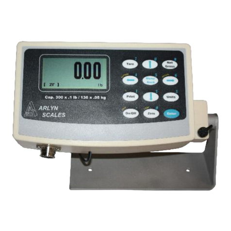
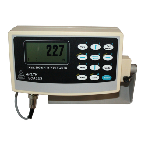
Arlyn Scales MKE-5 User manual

2
Introduction.......................................................................................................................................................................3
RS232 Communications Port............................................................................................................................................3
Configuring the Port 3
Perform Test Print 3
Loop Back Test 3
Print Stream Mode 3
Printing at Stability Using Motion Detection and Stability Control 3
Print Stream Mode with Print At Stability 4
Print Frame Definitions 4
Defining and Editing Print Frames 5
Print Frame Functions 5
Print Frame Design Examples 6
Text Definitions 6
Changing Printer Fonts 7
External Command Interface 7
The * Command, Keyboard Emulation 8
The ! Command, Remote Entry Commands [N/A: For Future Expansion] 8
The @ Command, Interactive Commands [N/A: For Future Expansion] 9
Tips on Interfacing RS232 9
Time and Date..................................................................................................................................................................10
Analog Output .................................................................................................................................................................10
Analog Setup Menu 10
Special Note for Multiple Platform Scales 10
Setpoint Controller ..........................................................................................................................................................11
Output Specifications and Notes 11
Creating Setpoints and Formulas 11
Output Connector and Pin Diagram 13
Weight Averaging............................................................................................................................................................14
Push Button Operation 14
Continuous Operation 14
Configuring the Weight Average Option 14
Multiple Platform Operation ..........................................................................................................................................14
Battery Pack Operation...................................................................................................................................................15
Description 15
The Main Power Toggle Switch 15
The Front Panel On/Off Switch 15
Auto Shutoff Setup 15
Statistical Package [N/A: For Future Expansion] ........................................................................................................15
Statistical Menu 15
The Setup Screen, Configuring the Statistical Package. 16
Adding a Reading to the Collection 16
Key lock option ................................................................................................................................................................16
General description: 16
To set password: 16
To unlock keys: 16
To deactivate key lock option: 16
Data Logging...................................................................................................................................................................17
Basic Operation 17
USB Flash Drive Use 17
Advanced Operation 18
Bluetooth..........................................................................................................................................................................18

3
Introduction
This manual will cover the operation and setup of all of the options available for your scale. It is important to note that some
described menu items will be missing if that option was not installed in your specific scale. All of the options listed may be
installed in any scale and may run concurrently. Any of the options may be installed later at the factory if it wasn’t installed at
time of purchase. Call our service department for details.
RS232 Communications Port
The RS232 option is a fully capable, bi-directional communications port. The port can be configured to operate at a variety of
baud rates and the output data frames are definable by the user. The printing of a frame can be initiated by pressing the print
button, by an external command, upon reaching a setpoint, or continuously when the print stream mode is activated.
The communications port also contains an extensive external command interface allowing key presses, adding and editing
memory slots and even scale calibration to be controlled from external equipment.
Configuring the Port
Baud rate and other parameters can be configured through the Port Configuration screen that can be accessed under menu
SETUP MENU/OPTION SETUPS/RS232/PORT CONFIG .The options are shown below.
BAUD RATE Settable to 110, 150, 300, 600, 1200, 2400, 4800, 9600, 19200, 31250 or 38400 bits per second.
DATA BITS Seven or Eight
STOP BITS One or Two
PARITY Even, odd or none
ECHO On or off. When echo is enabled the scale will echo each character the scale receives back to the user.
Perform Test Print
As an aid to port configuration we have included a “perform test print” function to the RS232 menu. Executing this will cause
the string “Your RS232 port is working fine!”, a carriage return and a line feed to be output from the port. To access this
function go to the menu SETUP MENU/OPTION SETUPS/RS232/PERFORM TEST PRINT.
Loop Back Test
You may also test the operation of the RS232 port by performing a loop back test. On the output connector, TX and RX
(transmitted and received data) need to be shorted together. When you perform the test, the scale sends data and reads it
back through its own port, where it is compared and the results are show.
Print Stream Mode
Print stream mode will continuously print the currently active print frame at fixed time intervals. Stream mode can be
configured using menu SETUP MENU/OPTION SETUPS/RS232/PRINT STREAM. The lower menu selection ENB will
enable or disable print stream mode, and TIME will be the number of seconds between the beginning of each print frame.
Time settings of .5 to 1638 seconds (27.3 minutes) can be entered. Avoid using time values of less than .5 seconds as it
may slow down or lock up the scale.
When stream mode is enabled, use the print button or the external *P command to start or stop the printing process.
Printing at Stability Using Motion Detection and Stability Control
All Arlyn digital indicators have the capability of detecting motion and/or stabilizing the weight and using it to control printed
outputs. This can be useful in many applications. For example, if you wanted to print labels for several items, you could
simply place each item on the platform, and when the scale gets a stable reading it will print the label automatically. The
Motion Detect, Stability and printing at stability are fully configurable through their respective setup screens.
The Motion Detect indicator looks like an ‘M’ and it is located just to the right of the Zero Indicator / Bar Graph located on the
bottom of the display. It is crossed out if there is no motion, and it is uncrossed if there is motion.
The Stability Control indicator looks like a circle and it is also located just to the right of the Zero indicator/Bar Graph located
on the bottom of the display. The circle is unfilled when the weight is not stable and filled when the weight is stable.

4
Print at Stability configuration allows the user to choose what control they want to use to print. The user can choose Motion
Detect only, Stability control only, or both Motion Detect and Stability control. Take a look at the Instructions Manual to see
how the Motion Detect and Stability Control can be set.
Sending a PRINT command or pressing the PRINT button on the front panel will send a PRINT request to the scale, and the
scale will only print if the motion and stability conditions are met.
The Print At Stability Setup Screen
Follow the menu tree down this path to locate this setup screen:
SETUP MENU / OPTION SETUPS / RS232 / PRINT AT STABILITY.
There are five settings that control this function:
ACTV: This will activate or deactivate this function. Select ACTV from the horizontal menu on the bottom of the screen, and
then press ENTER to change this setting.
PCT: This is the percent of full scale capacity, which, if the scale reading falls below, will not automatically print. For
example, a 100lb full capacity scale set to 1% will not automatically print when there is less than 1 lb on the platform. In most
applications there is no purpose to generating a print after removing weight from the platform. This percent can be set to two
decimal places.
TIMEOUT: This is the time set by the user to timeout retrieval of the value after a certain period of time. By default, this value
is 0, which means that the scale is never going to timeout to print a weight values. It will continue to look for a stable point to
retrieve a weight value for printing. If the number is set other than 0, then this is the period that the scale will try to print a
weight value, and if it fails, it will print “TIMEOUT” in ASCII on the terminal.
NEG: By setting this to "YES", the automated print will work on both sides of zero. When set to "NO" it will only work with
positive weights. The user must take into consideration here that if this parameter is set to “NO”, then when the scale is
reading zero, the output may be erratic even though the scale is stable. This is because the value 0 in the scale is not a true
stable zero. The zero here may be a long decimal that goes beyond the resolution. In this case, the value maybe negative
and therefore, impeding the printing process. It is recommend to set this to “YES” if the zero value is important.
ZERO NTFY: If this option is set to “YES”, then each time the scale is zeroed or a zero command is sent through one of the
communication ports, the indicator will wait for the scale to stabilize and detect if there is no motion. Once these conditions
are detected, the word “ZERO” appears on the output terminal in ASCII.
CONTROL: This option can be switched between Motion, Stability, Motion and Stability based on your preferences. This
determines how you want the Print at Stability to operate, whether based on Motion Detect, Stability Control or both. It is
important that when you choose these options, these features need to be activated within the system to operate properly.
Print Stream Mode with Print At Stability
Print Stream and Print at Stability can work together. If you want the scale to print weights constantly, then activate both of
these features together and they will work in tandem with each other.
Print Frame Definitions
A print frame is a list of up to ten functions for the scale to perform each time a print request is received. The list is executed
in the same order as shown is shown. A function can either be an item to be printed or a command for the scale. Currently
there is only one command and it is the CHAIN command. All other functions are items to be printed. If more than ten
functions are needed, as when defining print frames for complex labels, the CHAIN command can be used to chain to
another print frame definition.
Each print frame requires two memory slots. You can define as many frames as you like up to the number of free memory
slots available.
Each frame has a description associated with it. Descriptions are useful when you have many print frames defined, as when
you have multiple labels etc.
Only one frame can be active at any one time. Whenever the scale receives a print request, the currently activated frame will
be printed. The active frame is showed in the list with a check mark next to it.

5
Defining and Editing Print Frames
Go to the menu SETUP MENU/OPTION SETUPS/RS232/PRINT FRAMES.
To activate, edit or delete a frame, use the arrow keys to line up on the desired frame and ACTV, EDIT or DEL on the lower
menu and then press ENTER.
To define a new frame, use the arrow keys to select NEW on the lower menu and press ENTER. A new frame entry will be
added to the list. Use the arrow keys to line up on it and on EDIT in the lower menu. Pressing ENTER will bring you to the
frame editing screen. The screen will show “None defined” as there are no functions defined yet. For this example we will
make a simple data frame that will print the weight, followed by CR and an LF. Line up on NEW on the lower menu and then
press ENTER to add a function. The function NULL will be added to the list. We want to change this to the WEIGHT
function. Press the right arrow key to line up on FNC+ on the lower menu. Press ENTER twice to select the WEIGHT
function. To add a CR to this function, use the right arrow key to line up on CR on the lower menu and then press ENTER.
You will then see a check mark under the column “C”. To turn on the LF, press the right arrow once more to line up on LF
and then press ENTER. This completes the definition.
If you wish to change the description of this new frame, use the arrow keys to line up on DESC on the lower menu and then
press ENTER. Its current description will be loaded into the text-editing screen. Change it as desired and then press MENU
to return to the frame editing screen. To use this new frame press MENU to back out to the frame list. Use the arrow keys to
line up on the new frame and also ACTV on the lower menu. Press ENTER and a check mark will show on the new frame
showing that it is activated.
The lower menu items on the frame editing screens are outlined below.
DESC Allows you to change the description of this frame.
NEW Adds a new default function (NULL) to the function list.
INS Will insert a new function (NULL) before the currently selected function line.
DEL Will delete the currently selected function line.
FNC+/- Will change the function of the current line. Available functions and their explanations are outlined below.
SRC On many of the functions you need to specify the source of the data. For example the WEIGHT function must know
what platform (on multiple platform scales) the reading should come from. SRC will step through all available platforms. For
a TEXDEF function, it will step through all the available text definitions. For a CHAIN function it will show a list of other
frames that you can chain to. For ASCII you can enter the decimal value of the ASCII code. For ChFont, using SRC will
enable you to step through all available choices.
CR Will include a carriage return at the end of the current function.
LF Will include a line feed at the end of the current function.
SP Allows you to print space(s) at the end of the current function. When activated a “?” will show up in the function list
on the current line and allow you to enter a number. The number of spaces must be between 0 and 15.
TEST This will allow you to quickly test the print frame without having to return to the scale’s normal operating mode.
Print Frame Functions
You can add up to ten functions to each frame. The functions are executed in the order they are defined in the list. You can
add a CR (carriage return), LF (line feed) or trailing spaces to most functions. This is useful when designing labels.
If a CHAIN function is encountered, the scale will ignore any further functions in the current frame and immediately chain to
the next frame.
Function List
NULL Does nothing, but allows CR, LF and spaces to be printed.
WEIGHT Prints a six digit weight value. It will be net or gross depending on mode. Use SRC to select the platform.
NETWGT Prints a six digit weight reading corrected for tare. Use SRC to select the platform.
GRSWGT Prints a six digit weight value ignoring any active tare weight. Use SRC to select the platform.
NGTEXT Prints “NET” or “GROSS” depending on mode. This is meant to be used with the weight function. Use SRC
to select the platform.
PLATTOT Prints a gross total reading of all active platforms.
COUNT Prints the current piece count. Use SRC to select the platform.
ACCUM Prints the value in the parts counting accumulate register. Use SRC to select the platform.
CNTACC Prints a total of the current piece count plus the part count in the accumulate register. Use SRC to select the
platform.
TIME12 Prints the current time in 12 hour format.. (when the time and date option is installed)
TIME24 Prints the current time in 24 hour format.. (when the time and date option is installed)
DAY Prints out the current day of the week. (when the time and date option is installed)

6
DATE Prints the current date in the format mm/dd/yyyy. (when the time and date option is installed)
SCADES Prints the 14 character scale description as entered in the system menu.
SCAID# Prints the scale ID number as entered in the system menu.
WEIGH# Prints the auto-incrementing weigh number who’s starting value was entered in the system menu. This
number will increment each time a frame is printed.
TEXDEF Prints a 14 character text string that was entered as a text definition. Use SRC to select the text definition.
UNITXT Prints a 3 character indication of the currently selected units conversion (lb, kg, oz etc).
TARDES Prints the 14 character description of the current active tare weight.
SMPDES Prints the 14 character description of the current active sample weight (parts counting).
ASCII Will send a single ASCII character to the port. Among other things this is useful to send ESC sequences to
the printer to change fonts etc. Use SRC to enter the ASCII code.
CHFONT Change Font. Works only with EPSON compatible printers. Use SRC to select the font.. See explanation
below.
CHPNT Change Point size. Use SRC to toggle through the choices 16,20,24,30,36,40,42,48,52,56,60,64
CHAIN Will end the current frame and initiate another. Use SRC to select the next frame. Avoid chaining to the
same frame, as this will cause endless looping.
Print Frame Design Examples
The first example is a simple print frame that will print the weight followed by a carriage return and a line feed.
FUNCTN SOURCE C L SP
Weight Plat#001 0
The next example shows a more complex definition. Here we will design a five line label.
Line 1and line 2 will be blank (used for spacing the label vertically).
Line 3 will show the time in 12hr format, followed by 1 space,
Line 4 shows day of the week with 1 trailing space.
Line 5 shows the date followed by a carriage return and a line feed.
Line 6 will show the scale’s text description (as programmed through the system menu) followed by 3 spaces.
Line 7 shows the weight followed by a carriage return and a line feed.
Line #8 will be blank (again used for spacing the label vertically).
FUNCTN SOURCE C L SP Comments
Null 0 Two blank lines. Note the check marks on C and L.
Null 0
Time12 1 Line #3, the time and 1 space
Day 1 Day of week and one space
Date 0 Date followed by a CR and LF
SCADES 3 Line #4, The scales description followed by 3 spaces
Weight Plat#001 0 The weight followed by a CR and LF
Null 0 Two blank lines. Note the check marks on C and L.
The label would look like:
11:31:43 Tue 12/03/1999
ScaleDescr +123.456
Remember that there are only 10 functions allowed per print frame, and we used nearly all of them in this example. If you
needed more you could define a second print frame and use a CHAIN function at the end of first frame to chain to the
second frame.
Text Definitions
Sometimes it is desirable to include text when printing a label. Each text definition allows you to define a 14 character text
string. To access text definitions, go to the menu SETUP MENU/OPTION
SETUPS/RS232/TEXT DEFINITIONS. A list of current text definitions is shown and you can NEW, EDT or DEL them in the
usual way. ACTV is not used here.

7
Changing Printer Fonts
If you have an EPSON compatible printer, you can use the ChFont print frame function to change to one of four fonts, turn
double wide on/off, double height on/off, italics on/of, letter quality/draft, bold on/off and printer reset. Not all point sizes or
other functions are available on all fonts. Also, not all fonts are available on all printers. Please consult your printer’s
instruction manual for details. The ChPnt print frame function allows you to scale the font size up and down.
The scale will send the appropriate “Escape Codes” to the printer to perform these functions. ChFont and ChPnt are only
meant to be a short-cuts to reduce the frame size. You could also perform font/point switching and many other printer
functions by using the ASCII function.
The following is a summary of the escape codes sent to the printer by the various sub-functions of ChFont;
Bold On ESC E <27 69> Bold printing ON
Bold Off ESC F <27 70> Bold printing OFF
Ital On ESC 4 <27 52> Italics ON
Ital Off ESC 5 <27 53> Italics OFF
Draft ESC x 1 <27 120 1> Select draft quality print
Let Qual ESC x 0 <27 120 0> Select letter quality print
Roman ESC k 0 <27 107 0> Select Roman font
Sans Ser ESC k 1 <27 107 1> Select Sans Serif font
Courier ESC k 2 <27 107 2> Select Courier font
Prestige ESC k 3 <27 107 3> Select Prestige font
Script ESC k 4 <27 107 4> Select Script font
Reset ESC @ <27 64> Initialize printer
DblW On ESC W 1 <27 87 1> Double width printing ON
DblW Off ESC W 0 <27 87 0> Double width printing OFF
DblH On ESC w 1 <27 119 1> Double height printing ON
DblH Off ESC w 0 <27 119 0> Double height printing OFF
ChPnt ESC X 1 n 0 <27 88 1 n 0> Select height in points. n = # of points
External Command Interface
The external command interface allows the user to control the scale and manipulate memory data through the RS232
interface. There are three basic command types, these are:
The * Command (Keyboard Emulation). This allows you to simulate key presses remotely.
The ! Command (Remote Entry). Allows you to add, edit and delete memory contents like tares and parts counting samples.
The @ Command (Interactive Command). Allows you to operate the scale interactively whereby you send commands to the
scale and the scale responds with text messages guiding you through various operations.
It should be noted that the command list described below is the proposed list of commands. As our scale continues to
develop, commands are added as each firmware revision comes out. The revision in which the command was added is
shown just to the right of the command in parenthesis. If (X) is indicated it means that the command has not been
implemented yet and is slated for future release. To check the revision number of your scale, watch the Arlyn Logo splash-
screen when you first turn on your scale. Firmware upgrades can be purchased and installed in your indicator. . Some
commands can be implemented based on customer request. If it is imperative for the customer to have a certain command
type, contact our service department for more information and to get quote for the functionality to be implemented.
Print Request Response Time
When the scale receives a print request (*P) there is a small time delay while the scale computes and formats its output
frame. For any frame function that outputs weight or parts count the response time is typically 100 milliseconds (1/10th
second). For almost all other frame functions the response is almost immediate.
External Command Limitations
It is important that when sending repeated print requests (*P) to the scale that you wait for the scale to completely transmit
its print frame, and then wait a small amount of time before sending the next request. If the scale receives a print request
while it is still transmitting, the scale could actually lock up requiring a power off reset. Also, it is advisable to wait a small
amount of time after the output frame is complete to give the scale a chance to do its own “housekeeping chores”. To
immediately send another print request directly after a transmission could bog down the scale’s displayed update rate and
keyboard response.

8
Command String Parameters
All command strings sent to the scale require a carriage return (hereafter called CR) to be sent at the end of the command
string. A CR is ASCII code 13.
Keyboard emulation commands (* commands) do not require a CR and the key press will be initiated right after the
command is received.
Many of the command strings require parameters. These are described below.
<descr> Any command that changes the contents of a memory slot will require a fourteen character description. This
description should exactly match the description of the item in question. The description must be 14 characters in length and
spaces should be used for any unused characters just as they are used in the scale’s setup menus. For example “Tare #001
“ and “Plat #001 “ are valid descriptions. Descriptions are case sensitive so format your output appropriately.
If the scale can not find the description in memory, the message “Error 2: Description not found. Aborting.” Will be sent
followed by a CR. The operation is then aborted.
<value> Some commands require numeric input. All numbers should be 9 characters in length with a decimal point at
character five. Valid values, for example, are 0123.4500 and 0001.0000. Use leading zeros as necessary to keep the
spacing correct.
If the scale receives a number in an incorrect format it will send the message "Error 3: Illegal numeric format. Aborting."
Followed by a CR. The operation is then aborted.
Command Abort Any command can be aborted at any time by sending a caret (^) character which is ASCII code 94. The
scale will respond by sending the text “Command aborted” followed by a CR (ASCII code 13).
Illegal Command If any text is received by the scale that isn’t in a correct command format , the scale will respond with
"Error 1: Illegal command." followed by a CR. The command is then aborted.
The [*] Command: Used for Keyboard Emulation
A number of external commands can be sent to the scale to simulate keyboard presses. These commands are listed below.
Each command must be prefixed with a * character and no CR is required.
*P or *1 - Print Key (5.000)
*C or *3 - Units Key (5.000)
*Z or *0 - Zero Key (5.000)
*N or *9 - Net/Gross Key (5.000)
*T or *7 - Tare Key (5.000)
*U or *8 - Up Arrow Key (5.008)
*D or *2 - Down Arrow Key (5.008)
*L or *4 - Left Arrow Key (5.008)
*R or *6 - Right Arrow Key (5.008)
*. –Decimal Point (5.008)
*O - On/Off Key, will take the scale in and out of Ready Mode (5.008)
*M or *5 - Menu/Back Key (5.008)
*E - Enter Key (5.008)
Care must be taken when sending key commands via RS232 as some keys will perform different functions depending on the
scale’s operating mode.
The [!] Command: Remote Entry Commands [N/A: For Future Expansion]
Tares
NEW (X) !TN <descr> <value> <CR>
EDIT (X) !TE <descr> <new descr> <value> <CR>
DELETE (X) !TD <descr> <CR>
ACTIVATE (X) !TA <descr> <CR>
CLEAR (X) !TC simply clears the active tare.
ACQUIRE (X) !TQ <descr> adds new tare and becomes interactive for acq
Samples
NEW (X) !SN <descr> <value> <CR>
EDIT (X) !SE <descr> <new descr> <value> <CR>
DELETE (X) !SD <descr> <CR>
ACTIVATE (X) !SA <descr> <CR>

9
CLEAR (X) !SC <CR> simply clears the active sample.
ACQUIRE (X) !SQ <descr> <sample size> <CR> adds new sample and becomes interactive for acq
Print Frames
NEW (5.021) !FN <descr> <CR>
LINE EDIT (5.021) !FL<14 chr src descr> <1 chr line n# 0-9> <2 chr function code> <2 chr arg1> <3 chr arg2>
<CR y/n> <LF y/n> <2chr # spaces> <CR>
DELETE (5.021) !FD <descr> <CR>
ACTIVATE (X) !FA <descr> <CR>
Text Definitions
NEW (5.021) !XN <descr> <CR>
The [@] Command: Interactive Commands [N/A: For Future Expansion]
Remote Span Calibration (5.010)
Your scale can be span calibrated remotely using this function. The command format is
@CS <descr> <calibration weight value> <CR>
To do this procedure you will need a calibrated weight of a known value. For this example we will calibrate the scale’s
primary platform whose description is “Plat #001” with a 10 lb weight, the procedure is described below.
You send “@CSPlat #001 0010.0000<CR>”
Scale responds "Remove all weight from the platform and then send a CR.”<CR>
You remove the weight from the platform and send a CR.
Scale responds "Place the calibrated weight on the platform and then send a CR.”<CR>
You place the calibrated weight in the center of the platform and then send a CR.
Scale responds "Remove all weight from the platform and then send a CR.”<CR>
You remove the weight from the platform and then send a CR.
Scale responds "Operation Complete."<CR>
The scale will then remote calibrate itself and return to the weighing mode. You may have to press the ZERO key (or remote
zero key) to get the scale to indicate properly.
Future Interactive Commands
TARE-READ VALUE (X) @TV <descr> <CR> (sends <value> <CR> or NOT FOUND <CR>)
TARE-READ ALL (X) @TA <CR> (sends for each <descr> <value> <CR>. Sends END <CR> and end of list)
SAMPLE-READ VALUE (X) @SV <descr> <CR> (sends <value> <CR> or NOT FOUND <CR>)
SAMPLE-READ ALL (X) @SA <CR> (sends each <descr> <value> <CR>. Sends END <CR> and end of list)
Tips on Interfacing RS232
RS232 transmission and reception takes place over a three wire cable, one for transmitted data, one for received data and
one for ground. When wiring these lines to a standard RS232 25 pin D connector, the transmitted data line should be tied to
pin 3, received data to pin 2 and ground to pin 7. For 9 pin connectors, the transmitted data line should be tied to pin 2,
received data to pin 3 and ground to pin 5. In some situations, computers and other equipment require handshaking lines
to work properly. Many times this can be shut off to work with a three wire system. If not, you can wire the connector to “trick”
the computer etc. to work properly. This involves shorting the RS232 RTS and CTS line together and shorting the DTR and
DSR lines together. For 25 pin connectors short pins 4 and 5 for RTS/CTS and pins 6 and 20 for DTR/DSR. For 9 pin
connectors short pins 4 and 6 for RTS/CTS and pins 7 and 8 for DTR/DSR.
Shown below is a simple program written in BASIC that will open a com port at 1200 baud and then drop into a never ending
loop that will input frames of information and print them on the computer’s screen.
10 REM A simple example of a scale to com port interface
20 OPEN ”COM1:1200,N,8,1,CS,DS” AS #1
50 REM Never ending loop
52 REM Send a print request to the scale
55 PRINT #1,”*P”
59 REM Input scale’s transmitted frame
60 INPUT #1,FRAME$

10
69 REM display the results on the computer screen
70 PRINT FRAME$
75 REM Small time delay (at least 100ms, see External Command Limitations above)
80 FOR X=1 TO 20000
85 NEXT X
90 GOTO 50
Time and Date
When your scale is equipped with the time and date option you can get time and date and day of week readouts on the
screen or use them in RS232 output frames. The time can be printed in either 12 or 24 hour format. Consult the section on
Print Frame Functions for details. The screens for setting the date and time can be found under the menu SETUP
MENU/OPTION SETUPS.
Analog Output
This option is a fully configurable analog output port that can be configured for current loop outputs. The factory has preset
the output to 4-20 mA. This range is configurable and it is explained in the second paragraph of this section. The output
follows the display and its gain is based on the platform’s programmed overload point. For example, in the case of a 100lb
scale whose output is configured as 4-20mA, 0lb = 4mA, 25lb = 8mA, 50lb = 12mA and so on.
The starting and ending currents can be configured by the user. For example the output’s starting and ending points can be
set 4mA to 20mA. Further, there is an option allowing negative displayed numbers to be output for cases where a reading
below zero needs to be monitored. As an example, a 100lb scale is setup with its starting current at 10mA and ending
current at 20mA, giving the output of -100lb= 0mA, -50lb = 5mA, 0lb = 10mA, 50lb = 15mA and 100lb = 20mA.
The Analog Output can also be configured to output voltage. The output can be configured for a voltage range between 0-
5VDC. This configuration can be requested to be done at the time of processing the order. However, this can also be done
by the customer. Simply connect a 250 ohm ¼ watt resistor between the output terminals. Set the starting and ending
currents to be 0mA and 20mA. Using Ohm’s law (V = I x R), you will get from 0VDC (0mA x 250 ohm = 0V) to 5VDC (20mA
x 250 ohm = 5V). Just put a voltmeter across the terminals to get these values.
Using any value of the resistor, the scale can be configured to output a customized range of voltages based on customer
requirements. However, the voltage cannot exceed 6VDC. The current output component cannot support a voltage drop
larger than this value.
Analog Setup Menu
The analog setup menu can be found under menu SETUP MENU/OPTION SETUPS/ANALOG OUTPUT.
Programmable parameters are as follows:
ACTV - Will activate or deactivate the option.
START - The starting current that will correspond to zero on the display.
END - The ending current that will correspond to the full-scale weight on the display.
NEGRDG - Allows negative displayed readings to affect the analog output. If disabled, the output will stop at the
programmed starting current when there is a negative number on the display. This should not be confused with a negative
current on the output. The lowest possible current is zero.
Special Note for Multiple Platform Scales
The analog output module used in the scale is a single channel module. Only a single output from a single platform can be
seen. For scales with multiple platform, the analog output will reflect accordingly with the multiple platform settings you have.
For multiplatform scales, you can monitor the weight from each platform on the indicator screen by using the UP/DOWN
arrow keys and SHIFT key. The analog output will only reflect the current platform seen on the indicator screen. For
example, if the screen is showing weight for Platform 1, the analog output reading will be for Platform 1.
Indicators equipped with multiple platforms also have a special screen that shows the weights on all the connected platforms
and the total from all of these platforms. In this screen, there is an arrow that indicates the actions that can be taken on the
indicated platform. If the arrow is on Platform 1, then the analog output will reflect Platform 1. The same applies for platform
2. While in this screen, the analog output can also reflect the total sum of weights on all the platforms.

11
To do this, press the SHIFT key and SIX key in sequence (not together). When this feature is activated, the analog output
will only reflect the total. It won’t reflect on any of the platforms. Press the SHIFT + 6 key sequence again to remove the
analog output for total weight feature.
Setpoint Controller
The setpoint controller gives your scale the capability to output a signal to external equipment when certain conditions are
met. This is particularly useful in filling operations, either to sound alarms or to control filling machinery.
Setpoint definitions can be created, edited and deleted. Each has a text description, controlling parameters and a multi-line
formula associated with it. In operation, if the displayed weight satisfies the formula, you may direct any of the outputs to
switch on or off. You can create as many setpoint definitions as you like within limits of free memory. Each setpoint uses four
memory slots.
Setpoint definitions can be activated or deactivated, and up to four setpoint definitions can be activated at one time. When
multiple setpoints are activated, each setpoint formula is evaluated in the order it was defined. If more than one setpoint
shares the same output, then it is possible for one to overwrite the other.
With a little finesse in creating formulas, simple setpoints, filling control cycles, over and under check weighing, and many
other functions are possible.
IMPORTANT NOTE: During Scale reboot, the scale will momentarily toggle all setpoints to check for malfunction. This might
cause your valve systems to open (or close) during that initial moment. A fix is already being implemented (as of this writing)
for this issue. All Software versions at 6.123b and below will have this feature. A workaround would be to add a manual
switch that would be used to shut off your system if the scale is every rebooted.
Output Specifications and Notes
The setpoint controller has eight separate outputs and is expandable to sixteen. Each output is an open collector that is
capable of sourcing 4.5ma or sink 10ma of current. Care must be taken not to exceed these values. This is sufficient to drive
LEDs or sound buzzers. If higher output currents are needed then external relays need to be installed. We normally provide
117VAC, 10Amp optically isolated relays and mechanical relays should be avoided. We also provide 60VDC DC relays.
Optical relays have some important advantages over mechanical relays, the actuation current for optical relays is usually
less than 10ma but mechanical relay coils require currents often exceeding the limit. Optical relays have no mechanical
switches to wear out and more importantly they isolate the scale from the load, thus protecting it from voltage spikes. If
excessive noise is coupled back to the scale it could lock up or damage its microprocessor or memory.
It should be noted that when you command an “OFF” CONDITION, the output will be grounded. In most open collector
(switched ground) wiring schemes this will actuate the external light or relay. To help eliminate this confusion, each setpoint
formula has a optional invert function to invert the output.
Even though the output is an open collector, it differs from the standard open collector output in that the output will assume a
high condition (3.3VDC) when it is switched on without the need for an external pull up resistor, allowing direct connection
into any TTL level input.
Creating Setpoints and Formulas
To access setpoints, go to the menu SETUPMENU/OPTION SETUPS/SETPOINT CONTROLLER. There you will see a list
of all available setpoints or “None Defined” if none exist. The creation, editing and deletion of setpoints are similar to the
creation of tares and parts counting samples. To add a new setpoint definition, select NEW on the lower menu and press
ENTER. A new setpoint definition will then be added to the list with a description of “SetPt #XXX”. This new setpoint is
deactivated and contains an empty formula list.
To edit this new setpoint, or any other one, use the UP and DOWN ARROW keys to line up on the desired setpoint, select
EDIT on the lower menu and then press ENTER. The setpoint definition screen will be shown.
The Setpoint Definition Screen
The setpoint definition screen will show the description and controlling parameters for this setpoint definition.
INV=On/Off: If it is on then all outputs related to this setpoint will be inverted. This is useful when using the open collector
output for the reasons stated earlier in this section.
CYCLE=On/Off: The cycle option is used to create an operation cycle as described earlier in this section.

12
NEG=On/Off: The Negative option is used to determine if the scale needs to evaluate negative weight values. If NEG = Off,
then the setpoint controller will not evaluate negative weights, as in it will treat both negative and positive weights the same.
Example, if the display shows -10 lbs or +10 lbs, the setpoint evaluator will evaluate these values as positive values. If NEG
= On, then it will differentiate between the two values.
PLAT=PL1: This option only appears when the scale is equipped with Multiple platforms. The user can select if the setpoint
conforms to a particular platform. If it is the case, then the setpoint will only evaluate weights corresponding to that platform.
PARTS=On/Off: This option only appears when the scale is equipped with Parts Counting. The user is given a choice of
whether the setpoint should respond to count value instead of weight value.
To change any of these options simply select the appropriate entry in the lower menu and press ENTER.
Creating and Editing Formulas
The formula is a list of up to nine lines that are evaluated and acted upon in the order they are entered.
To access the formula list select EDIT in the lower menu and then press ENTER. All of the current formula lines will be
displayed or “None Defined” if there aren’t any. Using the NEW and INS in the lower menu to add or insert new lines.
Each line consists of four parts. These are CMD (command), EXP (expression), VALUE and OUT. CMD is an action to
take. The only two commands currently available are ON and OFF. EXP is an expression and can be < (less than), <= (less
than or equal to), > (greater than) and >= (greater than or equal to). Value is the setpoint weight value and OUT is the output
channel (1-8) that the CMD command will work on.
For example, a simple formula to activate the output when a certain weight is exceeded is made up of two lines as shown
below:
CMD EXP VALUE OUT
Off < 5.0 1 Start with light off
On >= 5.0 1 On if 5 lb or greater
This can be interpreted as:
Line 1: Output #1 is off if weight is less than 5.00 lb
Line 2: Output #1 is on if weight is greater than or equal to than 5.00 lb
You will notice that every output possibility must be dealt with when creating a formula.
The next example represents a much more complicated definition. The scale would have three lights connected to three
outputs and operate in an UNDER / ACCEPT / OVER check weighing scenario.
There will be a red light connected to output #1 to indicate an “under” condition, a green light connected to output #2 for an
“accept” condition and a yellow light connected to output #3 to show an “over” condition. We can program the red light to be
on whenever the weight is less than 5lb, the green light to be on only between 5 and 5.2 lb and the yellow light to be on
whenever the weight is above 5.2lb indicating an over condition. In practice, the user would start filling the container until the
green light comes on.
It is less confusing to make a formula of this nature if you deal with the complete operation of one light at a time. We
recommend laying the formula out on paper first and then enter it into the system.
Here it is:
CMD EXP VALUE OUT
On > 0.00 1 Deal with “under” (red) light first
Off >= 5.00 1
Off < 5.00 2 Now the “accept” (green light), to be
On >= 5.00 2 on only between 5 and 5.2 lb
Off > 5.20 2
Off <= 5.20 3 Now the “over” (yellow) light to be on
On > 5.20 3 anytime the weight is above 5.2
When this formula is executed, the scale evaluates each line in order. This calculation is done in memory only, and the
outputs are not affected until the formula is complete. The entire formula is evaluated on each and every display update,
which is programmable through the system menu.

13
You may wonder why it is necessary to have to use an Off condition at the beginning. This was done to increase flexibility as
there may be many cases where the user wants the light to start in the on state, turn off during a certain weight range and on
again when above that range. You have to specify every possible condition for the output when making formulas.
This last example will show an automated filling operation using the cycle option. The goal here would be to have output #1
connected to a filling valve and the cycle starting with this valve in the off condition. The user places a box on the scale
below the filling apparatus, press the ZERO key to zero out the weight of the box, press the ENTER key to start filling and
have the setpoint controller switch the filling valve off when 5lb is reached. The user then removes the box from the scale
and the output will remain off until the next cycle is initiated by pressing the ENTER key.
Start in the setpoint definition screen by enabling the CYCLE option and setting the INIT option to off.
Here is the formula:
CMD EXP VALUE OUT
On < 5.00 1 Will actually go on as soon as the ENTER key is pressed.
Off >= 5.00 1 Switch off at 5 lb and end cycle
That’s all there is to it. The output will go off at 5 lb and remain off until the next cycle.
Notes on Cycling Setpoints
The cycle function is used when it is desirable to “latch” the output to a specific state when a process is complete. Consider
the following examples with and without the cycle option. In both cases the setpoint is set to fill a box to 5lb and then shut off.
Cycle Off: The output is on as the box fills and the scale monitors the process. At 5lb the output switches off. The user then
removes the box from the scale. When he does that, the indicated weight falls below 5 lb, the filling valve switches back on
dumping material all over the platform.
Cycle On: When 5lb is reached the output switches off, and remains off until the user initiates the cycle again by pressing the
ENTER key.
There are two other points concerning process cycles:
There may only be one cycling setpoint definition active at any given time. All other activated setpoint definitions will
work normally along with it.
To abort the cycle, press the ENTER key. The output will then obtain the same state it would have taken if the
process had completed normally.
When changing the command line operations within a Cycling Setpoint Definition, you must REBOOT the scale for
the settings to take effect. This requirement is only for a Cycle mode setpoint. If you do not reboot, then the previous
settings will continue to remain active.
Output Connector and Pin Diagram
In most cases there will be a single cable with a 15 pin subminiature D type female connector added to the scale for
interfacing to external equipment.
1 Setpoint #4 Output
2 Setpoint #5 Output
3 Setpoint #6 Output
4 Setpoint #7 Output
5 Setpoint #8 Output
6 Setpoint #3 Output
7 Setpoint #2 Output
8 Setpoint #1 Output
9 Digital Ground (For Scales sold before 3/7)
10 +3.3 VDC
15 Digital Ground (For Scales sold after 3/7)

14
Weight Averaging
The weight averaging option allows the scale to display an average weight taken from the platform over a specific time
period. Readings are sampled from the platform forty times per second so a five second average would average 200
readings. Weight averaging can be setup to operate from a front panel key (the “8” key) or to operate on a continuous basis.
Push Button Operation
Pressing the “8” key will start the average. While the average is being taken, the status bar on the bottom of the screen will
display “Avg” and the graph bar will show the amount of time left. When the average is completed the result is locked on the
display and the text “Loc” will be shown on the status bar. While the reading is locked the UNITS, NET/GROSS and other
front panel keys will still operate as normal. To release the lock simply press the “8” key again. While the average is being
taken it can be aborted at any time by pressing the “8” key.
For Multiple Platforms
For Multiple platforms, if you have selected the Multiple Platform screen, then press the “6” button to perform
weight averaging.
Continuous Operation
When configured for continuous operation, constant averages at the selected time interval will be taken and locked on the
display. The text “Avg” will be shown on the status bar and the time progress shown on the graph line. The average key (the
“8” key) is used to start and stop this process.
Configuring the Weight Average Option
The configuration parameters for the weight average option can be found in the menu SETUPMENU/OPTION
SETUPS/WEIGHT AVERAGING. There are three settable options here.
ACTV Activates or deactivates weight averaging
TYPE Push button or continuous operation
TIME Average acquire time can be set from one to sixty three seconds
Multiple Platform Operation
Your scale has the capability of running up to three input devices at any one time. Normally only one is used, a load cell, and
the scale is programmed to have a single platform containing that load cell. The scale can be configured to run from multiple
platforms there are only a few basic operational differences:
1. An extra display screen is added showing the readings from each individual platform as well as the total weight from
all platforms.
2. When viewing individual platform screens, you can manually scroll through different platforms. Press SHIFT+UP in
sequence or SHIFT+DOWN in sequence to scroll through the platforms. On the primary weight screens the active
platform number is indicated on the bottom of the screen just to the right of the status bar (PL1, PL2 etc).
3. On the extra platform you can just use UP key or DOWN key without the need to press SHIFT key. For example, to
zero platform 2 use the DOWN ARROW to get the indicator on the right side of the screen to point at platform 2 and
then press the ZERO key.
4. An extra menu is inserted in the menu SETUP MENU/PLATFORM SETUPS. This is a menu that shows the
description of each platform and allows you select one for editing.
5. When taking or activating tares, parts counting samples, taking a quick sample or pressing the TARE, UNITS,
NET/GROSS or ZERO key, the operation will be performed only on the currently selected platform.
6. An auto-scroll feature is available in the Platform Setup screen. This feature allows the indicator to scroll through
individual weight screens at specified time intervals. To setup auto-scroll, go to SETUP MENU->PLATFORM
SETUP. Choose any activated platform and press EDIT. Scroll down to MULTIPLATFORM SETTINGS. Press
ENTER. The horizontal options and the screen text should be clear enough to set the correct settings. It is
recommended that the scroll timer should be set no less than 5 seconds. Any number lesser than that can cause
some instability in scale readings.
7. FOR DUAL PLATFORMS ONLY: To show the difference between the two platform scales, do the same steps as
defined in step 6 above. In the MULTIPLATFORM SETTINGS, select Platform Total to be either “Sum” or
“Difference”.
8. If the multiple platform scale has options attached to it, such as RS232, Analog Output, Setpoints, etc. make sure to
read the special notes for that section, if any, that might apply specifically for multiple platform operation.

15
Battery Pack Operation
See the addendum page 24 for quick operational instructions on this feature.
Description
The Battery Pack Option will allow the scale to be operated in areas where no power is available. The battery pack itself is
installed inside the indicator housing and is not user serviceable in any way. The only external differences are the addition of
a Main Power toggle switch and power transformer connector located on the right side of the indicator housing.
To charge the pack, simply leave the scale plugged in for about four hours. The charging circuitry has a peak detect and will
stop charging once the battery has reached its peak. The scale may be operating normally while charging.
The battery pack allows a scale equipped with a single load cell platform (models 620 and 820) to operate for about fifteen
hours on a single charge. For scales that have multiple load cell platforms, running time is slightly shorter. A four load cell
platform, like the model 320 will run for about 8 hours.
The Main Power Toggle Switch
There is a main power switch located on the right side of the indicator. Its only function is to completely remove power from
the main circuit board in the event of a microprocessor program crash or any other event that causes the scale not to be
able to switch itself off. This toggle switch is also responsible for charging the battery. If the toggle switch is left in the open
(DOWN) position, then the battery will not charge. This toggle switch should be left in the closed (UP) position during all
normal operation.
The Front Panel On/Off Switch
The front panel On/Off switch is used to switch the scale on and off during normal operation.
To turn the scale on, simply press the button and the scale will start its initiation sequence. To turn the scale off, press and
hold this button for approximately three seconds until the display blanks out and then release it.
Auto Shutoff Setup
The scale can (and should) be setup to automatically turn itself off when a programmed time has been reached and/or there
is no activity on the scale. This is done through the Auto Shut-Off screen. You may also want to skip the splash screen and
ready prompt on startup. You can do this in the menu SETUP MENU/SYSTEM/STARTUP PARAMETERS.
The scale’s auto shutoff operation can be activated and changed in the menu SETUP MENU/ SYSTEM /AUTO SHUT-OFF.
There are two options available.
ACT Activates/deactivates the auto shutoff feature.
TIME Is the time, in minutes, that the unit will shutoff due to inactivity.
Statistical Package [N/A: For Future Expansion]
The Statistical Package allows you to save a large number of readings in memory for future use. Here are some of its
features:
You can transmit the entire data collection through the RS232 communications port to a printer or computer for later
analysis.
You can view a “result screen” which will show the minimum reading, the maximum reading, the average, and total.
The data collection is held in memory even if the power is removed.
Readings can be saved by simply pressing a key.
Shares memory with the scale’s operating system for maximum storage efficiency.
Main screen shows when data collection is active and the number of readings collected.
Statistical Menu
This menu contains all of the functions associated with the statistical package. It is located at SETUP MENU / OPTION
SETUPS / STATISTICAL.
The items in this menu are:
SETUP: This is a simple configuration screen for the statistical package.
CLEAR MEMORY: This will clear all collected data from memory.

16
TRANSMIT DATA: This will transmit the entire data collection through the RS232 communications port. Each collected
reading is transmitted along with a carriage return (ASCII 13) and a line feed (ASCII 10). All collected readings are
transmitted. Memory does not automatically clear after transmission.
VIEW RESULTS: This screen will show some basic information about the data collected. These are the minimum reading,
the maximum reading, the total and average reading.
The Setup Screen, Configuring the Statistical Package.
This screen will allow you to specify if the statistical option is active or not, and also how much memory to set aside for data
collection. Any time you enter this configuration screen, the data collection in memory will be erased.
There are only two configurations on this screen:
ACTIVE: Set to YES in order to enable data collection. If enabled, the top line of the main weight display will show an inverse
“Data:”, followed by the number of readings currently collected in memory.
SIZE: The memory set aside for data collection uses the same memory and storage techniques as the memory used by the
scale’s operating system for storing tares, counting samples, print frames and other data. If you aren’t using the scale’s
memory for those other uses, you will have roughly 470 free slots available for data collection, depending on the scale’s
configuration. Each slot will hold 8 readings, so at maximum, 470 x 8, or 3760 readings may be collected.
To configure the memory, enter the new size through the setup screen. Size is the number of readings (maximum) that you
would like to be able to store. This number will automatically be rounded up to the next multiplier of 8 (8 readings per slot).
The memory is then set aside for data collection, and becomes invisible to the rest of the system. This being the case, if you
configure a large memory area for data collection, you will be restricted as to the number of storage slots available for other
uses.
Adding a Reading to the Collection
Simply press the ENTER key at any time while you are in the main weight screen. The current reading will be saved and the
top line will show you how many readings have been collected. If the data collection memory is full, you will see a warning
message at this time.
Key lock option
General description:
This key lock option adds the capability of disabling the front panel by having all of the function keys locked out, until a valid
password is entered. Once a valid password is entered, the keys will remain unlocked until the scale is powered down and
powered up. By default the option is not active until an initial password is set.
To set password:
1. Press the menu button. Unlock keys by entering the current password, if necessary.
2. Navigate to Options Setup and then scroll down to “Set Password”.
3. “Enter new password “ will appear on the display. Enter the desired password (4 digits long)
4. Confirm the password by retyping the intended password. Confirmation is used to assure that a mistyped password is
not stored.
To unlock keys:
1. Press menu button.
2. “Enter Password” will appear on the top line of the display. Enter the password previously set.
3. The function keys will remain unlocked until the scale’s power is powered down and powered up.
To deactivate key lock option:
1. Follow the above procedure for setting the password.
2. Instead of entering a password simply press enter twice.
3. This will clear the password and deactivate the key lock option until the password is set again.

17
Data Logging
The optional USB Data Logger module allows a large amount of data from your scale to be recorded into a USB Flash Drive.
The Flash Drive maybe removed from the scale and inserted into a standard USB port on a PC. The data is collected on a
.CSV file (comma-separated values), which can be opened using any spreadsheet software such as Microsoft Excel®.
Data Logger is activated by default. To activate/deactivate it, press Menu -> Option Setups -> Data Logging. On the
horizontal menu displayed in the Data Logging setup screen, select ACTV to activate/deactivate Data Logging.
Basic Operation
There are two modes of operation for using the USB Data Logger:
Triggered –The weight entry is written to the USB when the user presses a button
Continuous –The weight entry is written to the USB at regular time intervals selected by the user.
To switch modes of operation, on the Data Logging setup screen select TYPE on the horizontal menu to switch between
triggered and continuous type logging.
In Triggered Mode, press the TWO (2) key each time to log the current weight and time on the USB drive. This will be noted
by a “Recording Entry” message on the status message area of the screen each time the TWO key is pressed.
In Continuous Mode, press the TWO key to begin the data logging sequence. A “Data Logging On” message will be
displayed in the status area, followed by the “Recording Entry” message after the time interval has passed. After that,
“Recording Entry” message will appear on regular time intervals specified by the user. The time interval can be set in the
Data Logging setup screen. Select the TIME option on the horizontal menu to enter the time interval in seconds.
Note about Multiple Platforms
For Multiple platform, when the scale is in the Multiple Platform screen (where all the platforms are viewed at the same time
with a TOTAL), the TWO key is already occupied for switching between platforms. Instead, press the SHIFT key (ON/OFF)
and then the ENTER key in succession. Please make sure to see the “Shft” notification on the top left corner of the screen
before pressing the ENTER key. The ENTER key may have to be held a half-a-second longer to register the “Recording
Entry” notification.
The SHIFT+ENTER key-sequence will have the same effect as the TWO key described above in the Basic Operation
section.
USB Flash Drive Use
Your Data Logging scale comes with a 1 Gigabyte (1 GB) USB flash drive that can hold more than 4 million readings! For
those scales equipped with Data Loggers, the scale will always test the Data Logger system and check for a USB flash drive
at power up. If a USB Flash drive is plugged in, the scale will show the message “USB Stick found…” and if the USB flash is
not plugged in, then the message will simply say, “USB Stick not found…”. At times, the scale may show “USB Stick not
found…” even when a USB flash drive is plugged in. In this case, simply recycle the power and it should initialized the Data
Logger system correctly.
If the USB flash drive has never been used with the scale, the scale software will create the file DATA.CSV automatically.
This is the file the scale uses to store the weight entries. When recording new data on a card that already contains the file,
the scale will look for the file and append the new weight entries to the end. This file can then be opened using Microsoft
Excel® or a text editor.
It is okay to remove the USB drive while the scale is on. But if the user wants to plug in the USB drive back again, the user
has to:
Shut off the scale,
Plug in the USB drive,
Wait for 5 seconds
Turn on the scale.
The USB drive cannot be plugged in while the scale is on since the USB Data Logging system initialization routine happens
only at power up. But there is no harm if the USB drive is plugged in while the scale is on and an attempt is made to write
data into it. In this case, the status message will display “Recording Entry”, followed by “Can’t Open File…” This means that
the file DATA.CSV cannot be opened at this time.

18
The USB drive comes pre-formatted. It is not recommended that you reformat the USB drive.
When deleting weight entries from the USB Flash Drive, it is important not to leave the file empty. The data on the drive can
be anything - a period or a space or carriage return –so long as there is some data in the file.
If you are using the scale in Continuous Mode, we recommend that you temporarily put the scale into Triggered Mode while
the USB drive is plugged in and test it for operation.
Advanced Operation
WARNING: The following descriptions illustrate the advanced operation of changing the frames being printed on
the USB flash drive. Incorrect usage of the features described in this section will cause the scale to malfunction.
Proceed with caution.
The USB Data Logger can be used to store more than just the time and weight. The system uses Print Frames to determine
what data can be stored on the USB flash drive.
The Print Frames feature can be accessed by going to SETUP MENU/OPTION SETUPS/RS232/PRINT FRAMES. Ignore
the connotation RS232, as it only implicates the RS232 transceiver not present in these scales.
In the Print Frame Definitions screen, the frame named “USB” applies to the frame of data printed on the USB flash drive.
The factory default USB frame is:
FUNCTN SOURCE C L SP Comments
Time24 1 Line #1, the time and 1 space
Weight Plat#00X 1 Line #2, Weight
UniTxt Plat#00X √ √ 0 Line #3, Units
To change the frame to include more data types, you can refer to instructions outlined in the Print Frames section defined for
RS232 option in page 5.
Please note that a frame is only saved when the user moves out of the Print Frame Definitions screen. If the scale is
turned off while the user is still on this screen, the frame will be lost permanently.
Bluetooth
NOTE: Some options labeled as [N/A] are either not available or not fully implemented yet. Setting these parameters
may result into a serious malfunction of your Bluetooth device.
Introduction
The optional Bluetooth module allows you to transfer data wirelessly for a short distance to another Bluetooth unit. This is a
simple option, which uses the ease of use and popularity of Bluetooth devices for information transfer while stripping the
complexities and cost of higher-end wireless communication such as WiFi.
The Bluetooth module uses a Frame Definition database built into the scale to provide the user the ability to print custom
frames of data based on various requirements that may need to be accomplished.
Important Notes for Bluetooth Operation
Bluetooth devices have some notable limitations and some precautions need to be taken for proper Bluetooth
communication.
Maximum Distance
The Bluetooth module implemented in the scale is a standard Class 2 Bluetooth device. This means that it can only
communicate with another Bluetooth device within 30ft in the line of sight. If there are obstructions within this line of sight,
such as concrete walls, then that distance is further diminished.

19
Interference
It is recommended that to get the best signal out of the Bluetooth enabled indicator, no metal should be placed near the
indicator. Metals disrupt the signal coming from the Bluetooth module and might produce noise interference in the
communication resulting in corrupt data being transmitted. The metal also might cause the signal range to be diminished
causing serious reduction in communication range.
Overview of Menu Options
This section explains the various menu options available in the indicator to manipulate the Bluetooth module. The actual
sequence of the operation will be covered in the next section (see “Basic Operation”). These menu options can be accessed
by pressing MENU key on the main screen, then selecting OPTIONS SETUP->BLUETOOTH SETUP.
Bluetooth Reset
This menu option executes a soft reset on the internal Bluetooth. This reset is usually performed when the Bluetooth module
is performing erratically.
Scan Remote Devices
This option allows you to scan for any Bluetooth devices present in the vicinity. All Bluetooth devices scanned will be placed
in a database, which can be accessed using the “List All Devices” option.
Find Remote Devices [N/A]
This option allows you to scan for a specific device in the vicinity.
List All Devices
This option lists all the devices that have been scanned using the “Scan Remote Devices” option. In this list, you can check
the properties of a remote device, connect to a remote device and even check the connection status of a remote device.
Quick Connect Device
The Quick Connect option allows fast-connection to a particular device based on used defined parameters, without going
through menu options. The user may select the name of the device to connect to or the specific address. The connection
process is further explained in the section “Quick Connect Operation”.
Bluetooth Local Settings (Advanced)
This option allows the user to set settings for the internal Bluetooth module, such as the local name, aerial virtual COM port
and factory settings.
Basic Operation
Pairing and Default Pin
Please note there might be a need to pair the scale with the remote Bluetooth device. The default pin for the scale is ‘0000’.
As soon as you get the prompt to enter a pin for pairing on your remote device, enter the stated pin to commence pairing.
Pairing can be before or during the connection sequence. The Default Pin option is further explained in the Advance Settings
section. Instructions are provided on how to change the default pin, or if so desired, to eliminate the default pin and use
manual entry on the fly.
Connection
There are two types of connections that are going to be discussed in this section; Outgoing Connection and Incoming
Connection.
Outgoing Connection
Outgoing connection is the connection that the user initiates from the scale. The user has full control on how this connection
will be established. The following steps explain how to conduct this connection.
1. As recommended, before conducting any Bluetooth operations perform a soft reset of the Bluetooth module to bring
it to a known state.

20
2. To establish an outgoing connection to a remote device, you must first scan the area for that device so that the scale
can add it to its internal remote device database. From the Bluetooth Setup option menu, select “Scan Remote
Devices” to detect any Bluetooth devices in the area. You can also do this directly in the “List All Devices” section.
The following status messages should appear at the top of the screen.
“Scanning Remote Devices” - Obtaining remote device addresses from the vicinity
“Scanning Remote Names” - Obtaining remote names associated with the addresses obtained.
“Done!” - Operations done
3. Go to “List All Devices” to see what devices are available in the vicinity. In the “Bluetooth Devices” screen, you will
see all Bluetooth devices that have been detected in the area. If you don’t see the device you are looking for, select
the “SCAN” option on the horizontal menu below the list and press ENTER. Since the screen can only show you ipto
six devices at a time, you may have to use the UP and DOWN buttons to select a device as there maybe more than
6 devices detected. At the bottom of the screen, there are various operations that can be done on the devices
detected.
a. SCAN: Scan the surrounding area to find Bluetooth devices. The system will keep adding new devices to
the list without erasing the previous devices found. At some point, the list may become “stale” i.e. the list is
outdated and the devices in the list are no longer in the surrounding area. If this is the case, you may need
to clear the list. To do this, go back to the main menu and select “Scan Remote Devices”. Alternatively, you
can use “Bluetooth Reset” to clear the list.
b. CONN [CONNECT]:Connect to the selected remote Bluetooth device.
c. PRPT [PROPTERTIES]:Check the properties of the remote Bluetooth.
i. Name: Name of remote device
ii. Class: Device class of remote device, such as headset, desktop, etc.
iii. Address: Address of device.
d. STAT [STATUS]:Check the connection status of the remote device. This is only active if a connection has
been established.
i. Name: Name of remote device
ii. Connected: Connection status (YES or NO)
iii. Paired: Shows if the device is paired or not. [N/A]
iv. L. Port: The current local port used for connection.
v. R. Port: The remote port of the connected device.
vi. Signal: Signal strength of the connection.
4. Select CONNECT on the horizontal menu and press the ENTER key to connect to a desired device. If you see a
“Link Established…” message followed by a checkmark being placed besides the intended connected device, you
have successfully connected to the device. If you see any other messages, or the checkmark was not placed, then
the device was not connected.
5. To check the status of the connection, select STATUS from the horizontal menu. This will give some information
about the connection as stated in step 3.
6. Go back to main weight screen. A Bluetooth indicator ( ) shows at the bottom of the screen to indicate that a
Bluetooth connection is in progress. You can now use the PRINT button on the front panel to send weight
information to the remote device.
7. To disconnect, go back to the Bluetooth Options menu, in “List All Devices”. Select the device that is currently
connected (the device with a checkmark beside it). Select CONNECT from the horizontal menu and press ENTER
key. The connection will be destroyed. The status message “Link Released…” will appear at the top of the screen. If
this status message does not appear, then the link was not released properly.
8. An easier way to disconnect is using the “Quick Disconnect” method. This is explained in the next section.
Incoming Connection
Incoming connection is the connection that comes from a remote device. The user of the scale can only choose whether to
connect or not to the incoming device, if pairing has been enabled (no default pins defined). The following steps instruct the
user how to manage an incoming connection.
1. If the incoming connection from a device is a new device that has never been used before, a Pin Entry dialog box
will appear if the default pin was not set (see Bluetooth Local Settings section). If the default pin was not set, and the
wrong pin is entered from the remote device, then the connection will not be established.
Other manuals for MKE-5
3
Table of contents
Other Arlyn Scales Scale manuals

Arlyn Scales
Arlyn Scales 3200 Series User manual

Arlyn Scales
Arlyn Scales MKE-5 User manual

Arlyn Scales
Arlyn Scales ARL-BR-IS Series User manual

Arlyn Scales
Arlyn Scales w/MKE-5 User manual

Arlyn Scales
Arlyn Scales MKE-5 User manual

Arlyn Scales
Arlyn Scales ArlynGuard S MKE-5-IS-SAW User manual

Arlyn Scales
Arlyn Scales 8200 Series User manual

Arlyn Scales
Arlyn Scales UPSCALE User manual

Arlyn Scales
Arlyn Scales 3250 Series User manual