Copyright © 2016 ARM Ltd. All rights reserved.
Debug and Trace Configuration
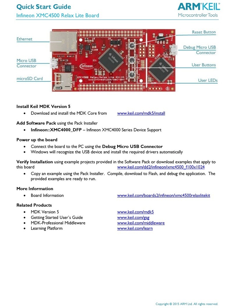
Infineon XMC4500 Hexagon Board
ULINKPro Debug and Trace Adapter
Connect the board to the PC using
the Cortex Debug+ETM
Connector and a debug adapter, for
example ULINKpro.In µVision,
select
Project –Options for Target –
Debug and choose ULINK Pro Cortex Debugger.
Click Settings and configure the Debug connection for Serial Wire Debug
(SWD) by selecting the Port SW.
Trace Settings
For full trace capability, configure ITM
Trace by selecting the Trace tab.
Check the Trace Enable box.
Set the Core Clock speed to
correspond to the CPU Core Clock.
Set Trace Port to
Serial Wire Output –Manchester.
Ensure to set the SWO Clock
speed to maximum 1.000000 MHz.
Other trace configuration settings are described in the ULINKpro User’s Guide.
Go to www.keil.com/mdk5/ulink/ulinkpro. Choose ULINKpro User’s Guide in the Quick Links and
continue with chapter Configure Cortex-M Devices for Tracing. Select the section that applies to the
device used in the project target and continue with the topic Enable 4-Pin Trace (ETM).


